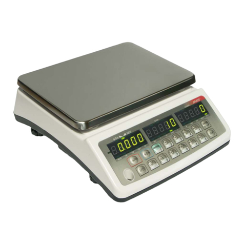
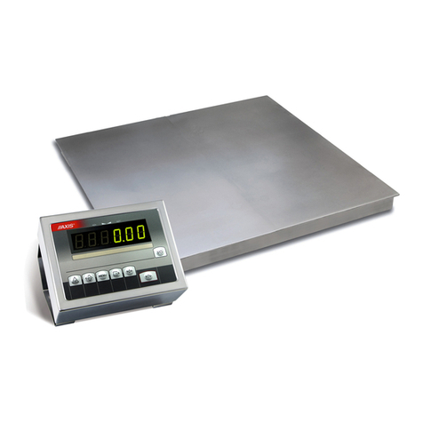
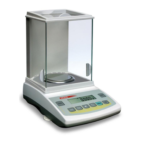
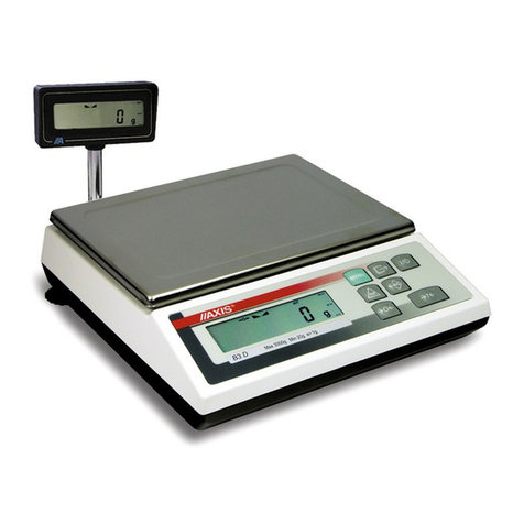
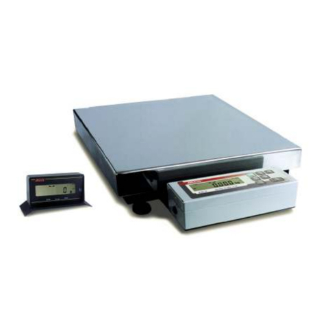
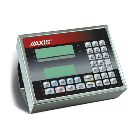
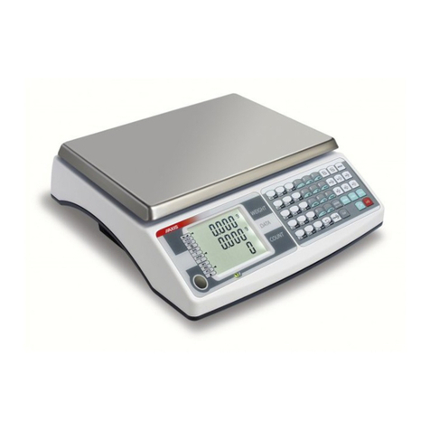
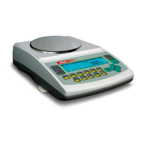
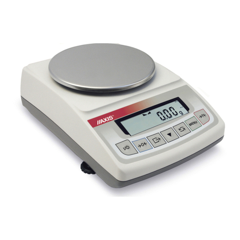
Axis 4B/F Series User manual

BALANCE INSTRUCTION MANUAL
SERIES 4B/F
File: 2012-04 R-4BF-046 B-50_4 GB

2
INSTRUCTION MANUAL
_____________________________________________________________________________________________________________________
Table of contents:
1. General description ................................................................................................................................................................ 3
2. Completation .......................................................................................................................................................................... 4
3. Tec nical data ........................................................................................................................................................................ 4
4. Balance keys and indicators .................................................................................................................................................. 5
5. Safety principles ..................................................................................................................................................................... 6
6. Principles of used balance treatment ..................................................................................................................................... 6
7. Foundation preparation .......................................................................................................................................................... 7
8. Balance installation ................................................................................................................................................................ 9
9. Balance start ........................................................................................................................................................................ 10
10. Operation principles ........................................................................................................................................................ 11
11. Balance test .................................................................................................................................................................... 12
12. Balance adjustment ........................................................................................................................................................ 12
13. Connection witc computer, printer or label printer ....................................................................................................... 12
14. Basic function.................................................................................................................................................................. 16
14.1 Normal weig ing ............................................................................................................................................................. 16
14.2 Weig ing wit tare .......................................................................................................................................................... 17
14.3 Increased readability ....................................................................................................................................................... 17
15. Special functions describtion .......................................................................................................................................... 18
15.1 Menu customization function (ACtIV and dEFAUL) ........................................................................................................ 19
15.2 Autozeroing function (AutoZE) ....................................................................................................................................... 20
15.3 Pieces counting (PCS) ................................................................................................................................................... 21
15.4 Printer cooperation settings (PrInt) ................................................................................................................................ 22
15.5 Serial port parameters setting (Port) .............................................................................................................................. 23
15.6 Constant tare (tArE) ........................................................................................................................................................ 24
15.7 Average calculation function (AVErAG) ......................................................................................................................... 26
15.8 Recipe weig ing function (RECIPE) .............................................................................................................................. 27
15.9 Percentage weig ing function (PErC) ............................................................................................................................ 28
15.10 Anti-disturbance filter function (FILtEr) ..................................................................................................................... 29
15.11 Function for maximum value indication (UP) ............................................................................................................. 30
15.12 Force measuring function (nEWto) ........................................................................................................................... 31
15.13 Function for weig ing large animals (LOC) ............................................................................................................... 32
15.14 C eckweig ing function (t r) ..................................................................................................................................... 33
15.15 Total weig t function (totAL) ...................................................................................................................................... 36
15.16 Function for setting date and time (dAtE) .................................................................................................................. 38
15.17 Function for selecting label number (LAbEL) ............................................................................................................ 39
15.18 External calibration (CALIb) ........................................................................................................................................ 40
15.19 Setting time of stabilization function (Stb) .................................................................................................................. 41
15.20 Entering reference zero function (Zero) ..................................................................................................................... 42
15.21 Automatic switc ing off t e scale function (AutoOF) ................................................................................................. 43
15.22 Density determining function (dEnSIt) ....................................................................................................................... 44
15.23 Statistical calculations function (StAt) ........................................................................................................................ 47
Maintenance and small repairs ....................................................................................................................................................... 49
Declaration of Conformity ............................................................................................................................................................... 50
Appendix A ..................................................................................................................................................................................... 51
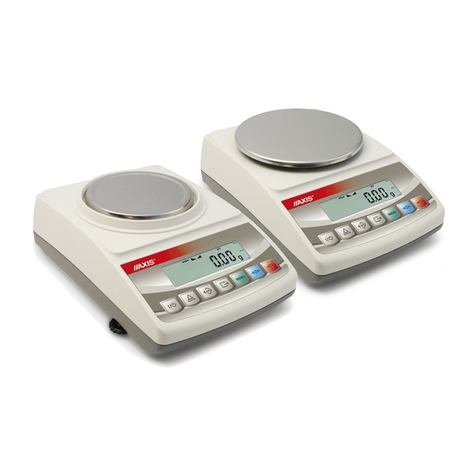
INSTRUCTION MANUAL
3
_____________________________________________________________________________________________________________________
1.
General description
Balances from 4B/F series in basic version from lacquered steel, with SE-
1/A/18 meter, are designed for operation in foundation structures, in light
environmental conditions.
Balances from 4B/F series from stainless steel, with SE- 1/A/18 meter, are
designed for operation in foundation structures, in hard environmental
conditions.
All balances are tested in respect of metrology. According to order, balances
may be verified or calibrated.
EC verification (conformity assessment) of balances is required for special
applications, mentioned in Ministry of Labour and Social Policy decree from
11.12.2 3 (trade, tariffs, pharmacy recipes, medical and pharmaceutical
analysis, packing of goods). For other applications it is recommended to replace
verification with calibration.
Verified balances have the following verification features:
- protection stamps, located on balance meter and converters connection box
(installed under the bearing surface).
- Office of Measures marks and green metrological mark, located on the rating
plate.
EC verification is valid for 25 months from 1st of December of year, when the
EC verification took place, under condition of stamp integrity.
Balances classification (PKWiU code) 29.24.23.
Certificates:
Certificate Certificate
of type approval DIN EN ISO 9 1:2
no. PL 4 2 no. 78 1 6386
(AXIS management system)

4
INSTRUCTION MANUAL
_____________________________________________________________________________________________________________________
2. Completation
Basic set includes:
1. Bearing surface and balance meter, connected permanently with cable
2. RS232C connector (only 4B/FN balances)
3. Instruction manual
4. Warranty
3. Technical data
Balance type
4B300F(N)
4B600F(N)
4B1500F(N)
4B2000F(N)
4B3000F(N)
Maximum load (Max)
300kg
600kg
1500kg
2000kg
3000kg
Reading graduation (d)
100g
200g
500g
1kg
1kg
Verification graduation (
e)
100g
200g
500g
1kg
1kg
Minimum load (Min)
2kg
4kg
10kg
20kg
20kg
Tare set range
-
300kg
-
600kg
-
1500kg
-
2000kg
-
3000kg
Precision class
III
Operational temperature
-
10÷40°C
Weig ing time
<3s
Foundation dept
1
28mm
Platform dimensions:
Balance
weig t:
1000x1000mm 140kg
● ● ●
1250x1250mm 170kg
● ● ● ●
1500x1500mm 210kg
● ● ● ●
1500x2000mm 300kg
●
Display cable lengt
4m
Power supply
~230V, 50Hz, 8VA
Meter protection rating
SE- 1/A/18 - no IP, SE- 1/N/18 - IP65
Sensors protection rating
IP68

INSTRUCTION MANUAL
5
_____________________________________________________________________________________________________________________
4. Balance keys and indicators
key
I/
- ON/OFF switch (standby),
key
→
T
←
- tare setting (entering of mass subtracted from weighed
mass),
key B/G - gross weight indication,
key
→
0
←
- zeroing,
key MENU - special functions menu,
key
- result print,
key HR - weight indication resolution increasing,
indicator
→
0
←
- zero indicator (for unloaded balance),
indicator - signals weighing result stabilization,
indicator
NET - net weight (after
→
T
←
key use),
indicator
- gross weight (after B/G key use),
indicator
- pieces counting function indicator (indications in pieces)
Additionally in LCD display version:
indicator MODE - special function activation menu,
indicator
bar - balance load indicator ( -1 %),
indicator YŁ -
balance switched off with key (standby),
indicator B/G - gross weight (after B/G key use),
indicator pcs - indications in pieces

6
INSTRUCTION MANUAL
_____________________________________________________________________________________________________________________
5. Safety principles
It is necessary to become familiar with safety principles
shown below, which are necessary to avoid electric shock
and damage of balance or connected devices.
• Maintain causion while opening the pan. It is suggested to
carefully hold the pan while opening.
• Repairs and necessary adjustments must be performed by qualified
personnel only
• To avoid fire hazard, use only typical supply cable, and supply voltage
must be consistent with technical data.
• For the balance supply use the socket with protective contact.
• Do not use balance when the cover is removed.
• Do not use balance in explosive atmosphere.
• Do not use balance in locations with high humidity, when the cover does
not have special protections for N type.
• In case of damage suspicion, switch the balance off and do not use it until
it is tested in professional service company.
6. Principles of sed balance treatment
According to valid regulations regarding natural
environment protection do not place used electronic
devices in containers with common waste.
• Used balance after operation period may be transferred to units authorized
for collection of used electronic equipment, or to place of purchase.

INSTRUCTION MANUAL
7
_____________________________________________________________________________________________________________________
7. Fo ndation preparation
CAUTION!
Decision of substrate reinforcing and density is taken by building works
designer.
All dimensions are in millimetres.
During foundation preparation follow the principles below:
1. Foundation and feet under balance legs should be made from concrete.
Foundation bottom thickness should not be smaller than 1 mm.
2.
Foundation bottom inclination angle (shown in fig. 1 on page 8) should be at
least 3%.
3. Keep the same level for all feet.
4. Level the foundation frame, keeping perpendicularity of sides and equality of
diagonals.
5. Diameter of PVC pipe for cables to connection box should be at least 5 mm.
6.
Keep the area free from reinforcing bars as shown in fig. 2 on page 8.
7. Foundation external and internal dimensions, proper for various platform
dimensions are shown in table below.
Balance type
Platform dimensions
[mm]
Foundation internal
dimensions
(WxLxH) [mm]
Foundation enternal
dimensions
(WxL) [mm]
4B300FN 800x800 820x820x110 1220x1220
4B300FN 1000x1000 1020x1020x110 1420x1420
4B300FN 1250x1250 1270x1270x110 1670x1670
4B600FN 800x800 820x820x110 1220x1220
4B600FN 1000x1000 1020x1020x110 1420x1420
4B600FN 1250x1250 1270x1270x110 1670x1670
4B1500FN 1250x1250 1270x1270x110 1670x1670
4B1500FN 1500x1500 1520x1520x128 1920x1920
4B2000FN 1250x1250 1270x1270x128 1670x1670
4B2000FN 1500x1500 1520x1520x128 1920x1920
4B3000FN 1500x1500 1520x1520x128 1920x1920
4B3000FN 1500x2000 1520x2020x128 1920x2420
Keep all dimensions, shown in drawings and table.
Careless and inacc rate fo ndation preparation may make balance
installation impossible or ca se its improper operation!

8
INSTRUCTION MANUAL
_____________________________________________________________________________________________________________________
Fig.1 Fo ndation – crosssection
Fig. 2 Fo ndation – view from above
300
70
180
180
65
65
300
210
210
Stopy pod nóżki wagi
200
Rama fundamentu
z kotwami
60
Kolekto do odp owadzenia wody
Ru a z PCV
na p zewód
Obsza wolny
od p ętów
zb ojeniowych
Rama fundamentu
z kotwami
Miejsca na kotwy amy
Feet under balance legs
Foundation frame
with anchors
Water collector
PCV pipe for cable
Places for frame anchors
Area
reinforcement
bar free
Foundation
frame with
anchors

INSTRUCTION MANUAL
9
_____________________________________________________________________________________________________________________
1
2
3
4
5
6
7
8. Balance installation
1. Balance structure
2. Screws fixing the limiter
3. Screws fixing base plates
4. Limiter
5. Base plate
6. Foundation
7. Balance leg
1. Prepare the foundation (7) according to guidelines (section 6) and engineering
technique principles.
2. Put the balances base plates (5) freely in the foundation.
3. Place limiters plates (4) on plates (5). Connect both plates with M8 screws (2)
so they cannot move in respect to each other, but to allow for limiters (4)
manoeuvring.
4. Unscrew screws fixing the balance upper plate.
5. Put the balance structure (1) in the foundation, so legs (7) fit vertically in the
limiters (4) holes.
6. Place upper plate on balance structure and lightly screw in the fixing screws.
7. Check the upper plate location in the foundation – level in relation to
foundation edge and distance from the edges (fig. 1).
8. When needed, shift the plates (5) or put spacers beneath them, made from sheet
with dimensions of plate.
9. If the position of upper plate is correct, carefully remove it to not move plates
(5). Check if legs (7) are straight.
1 . Carefully remove balance structure (1) from foundation to not move plates (5).
11. Fix plates (5) with supplied screws with steel pins.
12. Adjust possible displacements with plates (4) position, so legs are located
centrally and vertically in plates (4) holes. Tightly screw plates (5) and (4).
13. Put balance structure (1) in place.
14. Place the upper plate and fix it with screws, beginning from holes in the upper
plate centre.
Connecting cable m st be laid freely!

1
INSTRUCTION MANUAL
_____________________________________________________________________________________________________________________
15. Unpack the balance. Attach meter to the
wall or desktop, choosing one of three
methods.
16. Connect the supply cable plug to socket
with protective contact with unloaded
balance, which will cause autotests
performing and after indication stabilization
displaying of sero indication.
9. Balance start
Connecting of supply plug to socket of ~23 V/5 Hz installation with unloaded
balance will cause the following sequence of actions:
Display test
Tests of basic electronic subassemblies,
ended with messages: C1, C-2, ... C-6.
Displaying of software version.
Ready for operation.

INSTRUCTION MANUAL
11
_____________________________________________________________________________________________________________________
10. Operation principles
1. Before each measurement the balance should be properly zeroed, which is
signalled by “→0←” indicator. If the zero indication is not shown when the
balance is unloaded, or "----" is displayed, press the "
→0←
" key.
2. The balance enables tare setting in the whole measuring range. It is performed
by pressing "
→
T
←
" key.
3. Weighed mass should be placed in the platform centre.
Do not drop weighed objects on the platform.
Do not overload the balance over 20% of maximum load.
4. The weighing result should be read during the " " indicator lighting, which
indicates the result stabilization.
5. When there is no weighing, but the balance should be ready for operation, it may
be switched off by I/ key. It causes the balance reading system deactivation
end entering the standby mode. Balance turning on is performed by pressing "
I/ " key.
6. Protect the balance from dust, aggressive dusts and liquids. For cleaning
purposes use water and dry it.
Maintain causion while opening the pan. It is suggested to
carefully hold the pan while opening

12
INSTRUCTION MANUAL
_____________________________________________________________________________________________________________________
11. Balance test
During balance operation, in order to confirm its efficiency, it is recommended to
check the weighing precision by putting and object of exactly known weight before
and after series of measurements.
For testing of verified balances use weight standard, having valid standardization
certificates. In case of allowable measurement error exceeding contact authorized
service company to perform balance adjustment.
12. Balance adj stment
Balance adjustment must be performed by authorized service company
only, as it is connected with necessity of seals breaching, required for
warranty purposes.
13. Connection with comp ter, printer or label printer
The scale is equipped with RS232C or
RS485 (optional), which can be used to
connect external devices such as a computer
or a printer. Detailed way of communication
data is defined by one of protocol:
- LonG – protocol to printer and computer
- ELtron – protocol to label printer
When cooperating with a printer data is send
automatically after result stabilisation, but
next transmission is possible after removing
previously weighted sample.
When protocol Long is chosen scale sends
result of weighting under the influence of
initializing signal from computer, or after
pressing a key.
When automatic transmission mode is
chosen (function PrInt), a printer data is send
automatically after result stabilisation, but
next transmission is possible after removing
previously weighted sample. The scale sends
following information: successive number of
weighing, date and time (if clock module is
installed )and weighing result.
During transmission communicate Print is displayed. It is also possible by scale to
display text message sent from computer confirming received information.
RS-232C
RS485
(option)
RxD (receiver)
TxD (transmitter)
GND
Case
1
2
3
4
5
7
8
9
A
Input
Output
A
B
B
Case
1
2
3
4
5
7
8
9
}
}

INSTRUCTION MANUAL
13
_____________________________________________________________________________________________________________________
Scale with Eltron protocol sending record of data after pressed key.
The scale sends following information: number of label, date and time (if clock
module is installed ) and weighing result. During transmission communicate Label
is displayed.
In special features scale can be equipped in second RS232 interface for additional
functions, ex. continuous transmitting of indications to second display.
Computer must have a special program for cooperation with data from a scale.
Programs offer is available on www.axis.pl/en internet site.
Detailed protocol description
LonG protocol
Communication parameters: 8 bits, 1 stop bit, no parity, baud rate 48 bps,
Readout of scale indication ( corresponds to pressing key
Computer→Scale: S I CR LF (53h 49h Dh Ah),
Scale→Computer: scale response according to description below (16 bytes):
Byte
1 -
sign „-” or space
Byte
2 -
space
Byte
3
÷
4 -
digit or space
Byte
5÷9 -
digit, decimal point or space
Byte
1 -
digit
Byte
11 -
space
Byte
12 -
k, l, c, p or space
Byte
13 -
g, b, t, c or %
Byte
14 -
space
Byte
15 -
CR
Byte
16 -
LF
Attention:
Network number different than zero (F..-rS / nr function) changes scale working
mode: communication with a computer is possible after logging the scale in with
2h scale number command. To log the scale out use 3h command.
For example: Using a program to test RS232 interface ( program is available on
www.axis.pl in computer programs section) for scale number 1 please write: $0201
to log in, then SI, and write: $03 to close communication.

14
INSTRUCTION MANUAL
_____________________________________________________________________________________________________________________
Asking for scale presence in system (testing scale connection with computer):
Computer→Scale: S J CR LF (53h 4Ah Dh Ah),
Scale→Computer: M J CR LF (4Dh 4Ah Dh Ah),
Displaying a sign on scale display (text message from computer):
Computer→Scale: S N n n X X X X X X CR LF (53h 4Eh Dh Ah),
nn-displaying time in seconds; XXXXXX- signs to display
Scale→Computer: M N CR LF (4Dh 4Eh Dh Ah),
Scale tarring (calling
→
T
←
key press) :
Computer→Scale: S T CR LF (53h 54h Dh Ah),
Scale→Computer: without response,
Scale zeroing (calling
→
0
←
key press):
Computer→ Scale: S Z CR LF (53h 5Ah Dh Ah),
Scale →Computer: without response,
Scale turning on / off (calling
I/
key press):
Computer→ Scale: S S CR LF (53h 53h Dh Ah),
Scale →Computer: without response,
Entering to special function menu (calling MENU key press):
Computer→ Scale: S F CR LF (53h 46h Dh Ah),
Scale →Computer: without response,
Setting low threshold value (option):
Computer→ Scale: S L D1...DN CR LF (53h 4Ch D1...DN Dh Ah)
D1...DN – threshold value, maximum 8 characters („-” – negative value, digits,
dot – decimal separator), number of digits after dot should be the same as on
scale display,
Scale →Computer: without response,
Example:
⋅ in order to set low threshold 1 g in scale B1.5 (d= .5g) the following order
should be sent:
S L 1 . CR LF (53h 4Ch 31h 3 h 3 h 3 h 2Eh 3 h Dh Ah),
⋅ in order to set low threshold 1 kg in scale B15 (d=5 g) the following order
should be sent:
S L 1 . CR LF (53h 4Ch 31h 3 h 3 h 2Eh 3 h 3 h Dh Ah),),
Setting high threshold value (option):
Computer→ Scale: S H D1...DN CR LF (53h 48h D1...DN Dh Ah),
D1...DN – threshold value (see )
Scale →Computer: without response.

INSTRUCTION MANUAL
15
_____________________________________________________________________________________________________________________
Connecting cable WK-1 (scale – computer / 9-pin interface):
Protocol ELTRON description
Communication parameters: 8bits, 1stop, no parity, 96 bps,
After use key scale send:
Scale→Label printer : EPL-2 language instruction to initialize print of label:
US
-
control instruction
FR" 1"
-
number of labels
?
-
starting instruction
hh:mm
-
5 signs: hours:minutes
yyyy.mm.dd
-
1 signs: year.month.day
mass + unit
-
1 signs: scale indicate + mass unit
P1
-
ending instruction
Attention:
1. It is possible to place a constant signs (company name, product name).
2. The default number of label’s is 1 (label number 1).Different numbers of
label are possible by using a LAbEL function.
3. Label formula must be saved in printer – label forma must be designed in
computer (by Zebra Designer program) and saved in printer.
4. Parameters and protocol of transmission must be compatible with printer label.

16
INSTRUCTION MANUAL
_____________________________________________________________________________________________________________________
14. Basic f nction
To make clear how to manage with each function, in further part of instruction
descriptions are replaced with pictures.
- put a load on the pan
- remove the load from the pan
-
press the key when indication is
displayed
- forced change
- automatic change
14.1 Normal weighing
Press
→0←
key (
→
T
←
key in non-
legalized scales), which zeros the
scale, operates only when the pan is
empty .
Weighing result should be read when
the indicator " " lights.
0.00
2.30
0
2.30
T

INSTRUCTION MANUAL
17
_____________________________________________________________________________________________________________________
14.2 Weighing with tare
The scale is equipped with tare equal
to its range.
Joint value tare and mass net can not
cross a maximum of scale.
To display gross weight press B/G
key.
Note:
Press B/G key to return to net weight
indication.
14.3 Increased readability
Press HR key to display the weighing
result (for 5s.) with the highest
readability possible. This function is
especially helpful in scales with legal
verification with d=e.
The weighing result with increased
readability can be used for
informational purposes only and
cannot be printed or sent to a
computer with key.
2.30
0.00
40.01
42.31
T
NET
NET
2.30
2.29
2.30

18
INSTRUCTION MANUAL
_____________________________________________________________________________________________________________________
15. Special f nctions describtion
List of available functions:
menu customization function (ACtIV),
removal of all function from menu (dEFAUL).
autozeroing function (AutoZE),
pieces counting function (PCS),
function for setting serial port working (PrInt)
function for setting serial port (Port)
entering tare function (tArE)
recipe weighing function (rECIPE),
weighing large animals function (LOC)
force measuring function (nE to)
maximum value indication function (UP)
anti-disturbance filter function (FILtEr)
average calculating function (AVErA)
percentage weighing function (PErC),
extended calibration function (CALIb)
setting time of stabilisation function (Stb)
selecting label number function (LabEL)
automatic switching off scale function (AutoOF)
entering reference zero (Zero)
determining solids and liquids density function (dEnSIt)
calculator for good packaging control (tP) - option*
statistical calculations (StAt)- option*
paperweight calculation
function (PAP) - option*
function with additional equipment require:
options with the clock:
- setting current date and time function (dAtE)
- total weight function (totAL)
options with the transoptors connectors:
- checkweighing function (thr)
* Functions offered with special version of scale software (with limited possibility of using other
special functions).
User create own menu by choosing function in ACtIV function (described in chapter 14.1).

INSTRUCTION MANUAL
19
_____________________________________________________________________________________________________________________
15.1 Men c stomization f nction (ACtIV and dEFAUL)
Among available user functions it is
possible to select these, which should be
displayed after pressing MENU key. It
allows avoiding displaying whole list of
available functions, which makes
operation time longer.
Operation sequence shown in the
pictures on the left causes adding
function for setting serial interface
RS232C parameters (Port) to function
menu.
After switching on ACTIV function a
dot is displayed on the right side (to
distinguish from regular menu). Chosen
functions are displayed with a dot on
the left side.
In every moment, it is possible to
restore primary (manufacture) settings
choosing dEFAULt special function.
In order to remove function from menu
in the last operation in place of selecting
Port -1 choose Port -0.
0.00
ACtIV
Port -1
Port -0
PCS
.
.
.
Port
T
T
T

2
INSTRUCTION MANUAL
_____________________________________________________________________________________________________________________
15.2 A tozeroing f nction (A toZE)
When F..-Aut function is activated,
the scale automatically ensures stable
zero indication if the pan is empty or
if zero indication was acquired by
pressing
→
T
←
key.
To leave the function press MENU
key, then with
→
T
←
key chose
AutoZE and Aut-0.
Note:
Autozeroing function is activated
automatically for 10 min. after
switching-on.
0.01
AutoZE
Aut-1
Aut-0
0.00
T
T
This manual suits for next models
12
Table of contents
Other Axis Scale manuals

Axis
Axis 4B/NA Series User manual

Axis
Axis 4BA SERIES User manual

Axis
Axis BD/TL Series User manual

Axis
Axis LCD GB V4 User manual

Axis
Axis AKA/G Series User manual

Axis
Axis ATA1200 User manual

Axis
Axis BTA Series User manual

Axis
Axis AKA120 User manual

Axis
Axis ACG Series User manual

Axis
Axis B Series User manual

Axis
Axis BA/LG Series User manual

Axis
Axis B0.6D User manual

Axis
Axis BD/S series User manual

Axis
Axis AGN/C Series User manual

Axis
Axis B/E Series User manual

Axis
Axis 4BA SERIES User manual

Axis
Axis BLM Series User manual

Axis
Axis B/U Series User manual

Axis
Axis AG Series User manual

Axis
Axis AGN50 User manual