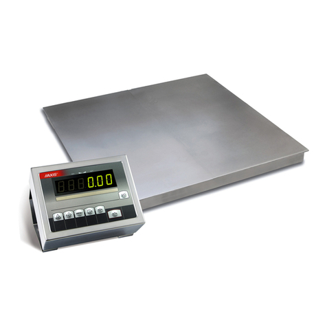
Axis 4BA SERIES User manual

USER MANUAL
4BA(N), 4BANA(N), 4BAF(N) , 4BAPZ(N) and 4BAPA(N) SERIES
File: 2014-03-20 ER-4BAxx bE0069 GB

2INSTRUCTION MANUAL
_____________________________________________________________________________________________________________________
Table of contents:
1. General description........................................................................................................ 4
2. Meters ........................................................................................................................... 5
3. Completation ................................................................................................................. 7
4. Technical data ............................................................................................................... 7
5. Meter ME-01 balance keys and indicators ................................................................... 10
6. Scale external outputs ................................................................................................. 12
7. Safety principles .......................................................................................................... 14
8. Balance preparation to work ........................................................................................ 15
8.1 Preparing platform, pallet and skid scales ................................................................... 15
8.2 Preparing overrun scales............................................................................................. 16
8.3 Preparing foundation scales ........................................................................................ 17
8.3.1 Preparing foundation......................................................................................17
8.3.2 Scale installation............................................................................................19
9. Balance start................................................................................................................ 21
10. Operation principles ................................................................................................. 22
11. Balance test ............................................................................................................. 23
12. Accumulator change (ME-01 option) ........................................................................ 23
13. Connection with computer, printer or label printer .................................................... 24
14. Basic function........................................................................................................... 28
14.1 Normal weighing ................................................................................................... 28
14.2 Weighing with tare ................................................................................................ 29
14.3 Increased readability............................................................................................. 29
15. Special function description...................................................................................... 30
15.1 Menu customization function (ACtIV and dEFAUL) .................................................... 31
15.2 Autotare function (AutotAr) ........................................................................................ 32
15.3 Pieces counting (PCS)............................................................................................... 33
15.4 Function for changing mass unit (UnIt) ....................................................................... 34
15.5 Percentage weighing function (PErC)........................................................................ 35
15.6 Recipe weighing function (RECIPE) .......................................................................... 36
15.7 Function for calibration with external weight (CALIb).................................................. 37
15.8 Label choosing function (LAbEL)................................................................................ 39
15.9 Serial port parameters setting (SErIAL) ..................................................................... 40
INSTRUCTION MANUAL 3
_____________________________________________________________________________________________________________________
15.10 Printout configuration (PrInt) ...................................................................................41
15.11 Function for weighing large animals (LOC) ...............................................................43
15.12 Constant tare (tArE) ..................................................................................................44
15.13 Function for maximum value indication (UP).............................................................46
15.14 Force measuring function (nEWto)...........................................................................47
15.15 Anti-disturbance filter function (FILtEr) .....................................................................48
15.16 Total weight function (totAL)......................................................................................49
15.17 Checkweighing function (thr).....................................................................................51
15.18 Function for setting date and time (dAtE) ..................................................................54
15.19 Radio communication channel choice function (rF CHn)...........................................55
15.20 Entering reference zero function (ZErO)....................................................................56
15.21 Setting backlight function (b_LIGHt)..........................................................................57
15.22 Charging accumulators function (bAttErY)- option.....................................................58
15.23 Automatic switching off the scale function (AutoOF) .................................................59
15.24 Statistical calculations function (StAt)........................................................................60
15.25 Paperweight calculation (PAP).................................................................................63
15.26 Main mass unit change function (lb_bAL) option....................................................64
16. Maintenance and repairs of small defects .....................................................................65
Declaration of Conformity....................................................................................................66
Appendix A..........................................................................................................................68

4INSTRUCTION MANUAL
_____________________________________________________________________________________________________________________
1. General description
This manual describes scales produces by AXIS Sp. z o.o. and their basic functions. Standard
execution scales are equipped with ME-01/A/LED meter and stainless steel scales with ME-01/N/LED.
In case of using these meters or special meter for eg. batching meter it is essential to use proper user
manual for individual meter type.
All balances are tested in respect of metrology. According to order, balances may be verified or
calibrated.
EC verification (conformity assessment) of balances is required for special applications (trade, tariffs,
pharmacy recipes, medical and pharmaceutical analysis, packing of goods). For other applications it is
recommended to replace verification with calibration.
Verified balances have the following verification features:
- protection stamps, located on balance meter and converters connection box (installed under the bearing
surface).
- Office of Measures marks and green metrological mark, located on the rating plate.
Balances classification (PKWiU code) 29.24.23.
Certificates:
Certificate ISO Certificate
of type approval PN-EN ISO 9001:2009
no. T7950 no. AC 090/1141/2245/2011
(AXIS management system)

INSTRUCTION MANUAL 5
_____________________________________________________________________________________________________________________
2. Meters
ME-01/A/LED - Standard universal ME-01 meter in aluminium
(A) housing and LED display (18mm digits height). Full set of
special functions (chapter 15) and standard set of keys.
ME-01/A/LCD - Standard universal ME-01 meter in aluminium
(A) housing and LCD display (18mm digits height). Full set of
special functions (chapter 15) and standard set of keys.
ME-01/N/LED –Standard universal ME-01 meter in stainless
steel housing and LED display (18mm digits height). Full set of
special functions (chapter 15) and standard set of keys.
ME-01/N/LCD - Standard universal ME-01 meter in stainless
steel housing and LCD display (18mm digits height). Full set of
special functions (chapter 15) and standard set of keys.
ME-01/N/25 –Universal meter with LED display (25mm digits
height) in stainless steel housing. Full set of special functions
(chapter 15) and standard set of keys.

6INSTRUCTION MANUAL
_____________________________________________________________________________________________________________________
ME-11/N/LCD (surcharge) meter with numerical keyboard
designed to operate special functions that need inscribing data
(e.g. product code, unitary mass), stainless steel housing.
ME-02/N/LCD (surcharge) designed for one-ingredient or multi-
ingredient batching, numerical keys, stainless steel housing.
SE-03/N/LCD (surcharge) designed to cooperate with label
printer, numerical keys, stainless steel housing.
SE-12/N/2xLCD (surcharge) - designed to operate with
computer through RS485 or LAN network, with possibility to
connect scanner and label printer (options), 2 displays: digit
weight indication and text - menu and data, stainless steel
housing.
SE-22/N/2xLCD meter (surcharge) one-ingredient or multi-
ingredient batching, 2 displays: digit mass indication and text
recipe ingredients names etc., stainless steel housing.
ATTENTION:
In order to get acquainted with special functions and other functionality use proper meter user manuals.

INSTRUCTION MANUAL 7
_____________________________________________________________________________________________________________________
3. Completation
Basic set includes:
1. The scale
2. RS232C connector (only 4BA/N, 4BA/FN, 4BA/PAN, 4BA/PZN scales)
3. CD with user manuals
4. Warranty
4. Technical data
Platform scales 4BA and 4BA/N
Scale type
4BA300(N)
4BA600(N)
4BA1500(N)
4BA2000(N)
4BA3000(N)
4BA6000(N)
Maximum load (Max)
300kg
600kg
1500kg
2000kg
3000kg
6000kg
Reading graduation (d)
100g
200g
500g
1kg
1kg
2kg
Verification graduation (e)
100g
200g
500g
1kg
1kg
2kg
Minimum load (Min)
2kg
4kg
10kg
20kg
20kg
40kg
Tare set range
-300kg
-600kg
-1500kg
-2000kg
-3000kg
-6000kg
Precision class
III
Operational temperature
-
Weighing time
<3s
Platform dimensions: Balance
weight:
1000x1000x80(85)mm 60kg
1250x1250x80(85)mm 100kg
1500x1500x80(85)mm 140kg
1500x1500x112(110)mm 150kg
1500x2000x112(110)mm 190kg
Display cable length
4m
Power supply
~230V, 50Hz, 8VA
Internal supply (option)
NIMH (size AA) 4 pcs
Accumulator working time
About 6 h with display backlighting and 16h without
Indicator protection rating
4B lack of IP
4B/N (stainless scales) - IP65
Sensors protection rating
4B - IP67
4B/N (stainless scales)- IP68

8INSTRUCTION MANUAL
_____________________________________________________________________________________________________________________
Overrun scales 4BA/NA and 4BA/NAN:
Scale type
4BA300NA
(N)
4BA600NA
(N)
4BA1000NA
(N)
4BA1500NA
(N)
4BA2000NA
(N)
Maximum load (Max)
300kg
600kg
1000kg
1500kg
2000kg
Reading graduation (d)
100g
200g
500g
500g
1kg
Verification graduation (e)
100g
200g
500g
500g
1kg
Minimum load (Min)
2kg
4kg
10kg
10kg
20kg
Tare set range
-300kg
-600kg
-1000kg
-1500kg
-2000kg
Precision class
III
Operational temperature
-
Weighing time
<4s
Platform dimension (max exter.
tread x lenght)
860x1000mm
1000x1250
mm
1250x1500mm
Overrun dimensions
1100 x 355 x 50mm
1250x415x50
mm
1500 x 470 x 60mm
Scale weight
160kg
250kg
350kg
Supply
~230V, 50Hz, 8VA
Internal supply (option)
NIMH (size AA) 4 pcs
Accumulator working time
About 6 h with display backlighting and 16h without
Indicator protection rating
4BA/NA - no IP, 4BA/NAN (stainless scales) - IP65
Sensors protection rating
4BA/NA - IP67, 4BA/NAN (stainless scales)- IP68
Pallet scales 4BA/PA oraz 4BA/PAN:
Scale type
4BA300
PA(N)
4BA600
PA(N)
4BA1000
PA(N)
4BA1500
PA(N)
4BA2000
PA(N)
4BA3000
PA(N)
Maximum load (Max)
300kg
600kg
1000kg
1500kg
2000kg
3000kg
Reading graduation (d)
0,1kg
0,2kg
0,5kg
0,5kg
1kg
1kg
Verification graduation (e)
0,1kg
0,2kg
0,5kg
0,5kg
1kg
1kg
Minimum load (Min)
2kg
4kg
10kg
10kg
20kg
20kg
Tare set range
-300kg
-600kg
-1000kg
-1500kg
-2000kg
-3000kg
Precision class
III
Operational temperature
-10÷40°C
Weighing time
<4s
Bearing surface internal dimensions
(width.x lenght.x height.)
600x1135x78mm
Bearing surface external dimensions
(width.x lenght.x height.)
840x1260 x78mm
Drive (entry) width
600mm
Display lenght to indicator
4m
Supply
~230V, 50Hz, 8VA
Internal supply (option)
NIMH (AA size) 4 pcs.
Accumulator working time
About 6 h with display backlighting and 16h without
Scale weight
70kg
Indicator protection rating
4BA/PA - no IP
4BA/PAN (stainless steel) - IP65
Sensors protection rating
4BA/PA - IP67
4BA/PAN (stainless steel)- IP68

INSTRUCTION MANUAL 9
_____________________________________________________________________________________________________________________
Skid scales 4BA/PZ and 4BA/PZN:
Scale type
4BA300
PZ(N)
4BA600
PZ(N)
4BA1000
P(N)
4BA1500
PZ(N)
4BA2000
PZ (N)
4BA3000
PZ(N)
Maximum load (Max)
300kg
600kg
1000kg
1500kg
2000kg
3000kg
Reading graduation (d)
0,1kg
0,2kg
0,5kg
0,5kg
1kg
1kg
Verification graduation (e)
0,1kg
0,2kg
0,5kg
0,5kg
1kg
1kg
Minimum load (Min)
2kg
4kg
10kg
10kg
20kg
20kg
Tare set range
-300kg
-600kg
-1000kg
-1500kg
-2000kg
-3000kg
Precision class
III
Operational temperature
-10÷40°C
Weighing time
<4s
height.)
1
Wire lenght beetwen skids
5m
Wire lenght to meter
5m
Supply
~230V, 50Hz, 8VA
Internal supply (option)
NIMH (AA size) 4 pcs.
Accumulator working time
About 6 h with display backlighting and 16h without
Scale weight
40kg
Indicator protection rating
4BA/PA - no IP
4BA/PAN (stainless steel) - IP65
Sensors protection rating
4BA/PA - IP67
4BA/PAN (stainless steel)- IP68
Foundation scales 4BA/F and 4BA/FN:
Balance type
4BA300F(N)
4BA600F(N)
4BA1500F(N)
4BA2000F(N)
4BA3000F(N)
Maximum load (Max)
300kg
600kg
1500kg
2000kg
3000kg
Reading graduation (d)
100g
200g
500g
1kg
1kg
Verification graduation (e)
100g
200g
500g
1kg
1kg
Minimum load (Min)
2kg
4kg
10kg
20kg
20kg
Tare set range
-300kg
-600kg
-1500kg
-2000kg
-3000kg
Precision class
III
Operational temperature
-
Weighing time
<3s
Foundation depth
28mm
Platform dimensions: Balance
weight:
1000x1000mm 140kg
1250x1250mm 170kg
1500x1500mm 210kg
1500x2000mm 300kg
Display cable length
4m
Power supply
~230V, 50Hz, 8VA
Internal supply (option)
NIMH (AA size) 4 pcs.
Accumulator working time
About 6 h with display backlighting and 16h without
Meter protection rating
ME-01/A/18 - no IP, ME-01/N/18 - IP65
Sensors protection rating
IP68

10 INSTRUCTION MANUAL
_____________________________________________________________________________________________________________________
5. Meter ME-01 balance keys and indicators
Version with LED display:
key
I/
-switch-on / switch-off (standby),
key
T
-tare (subtract package weight from weighed mass),
key
0
-zeroing (when the platform is empty),
key
-result printout,
key
MENU
-special function menu,
key
-switch: special function/weighing
key
HR
-high resolution,
indicator
0
-zero indicator,
indicator
-result stabilization indicator,
indicator
NET
-net weight indicator (after using
T
key ),
indicator
W1
-first range of two-range scale is on,
indicator
W2
-second range of two-range scale is on,
indicator
HOLD
-LOC and UP),
indicator
FUNC
-special function on,
indicator
PCS
-pieces counting,
indicator
g, kg,
lb, unit
-mass unit indication
indicator
MIN
-weighing result under threshold I,
indicator
OK
-weighing result between threshold I and II,
indicator
MAX
-weighing result above threshold II.
weighing
result
metrological
data
zero
indicator
MAX
W1
0 NET
W2 HOLD TOTAL FUNC PCS
g
kg
lb
unit
MIN
scale
keys
stabilization
indicator net weight
indicator
Max= d=

INSTRUCTION MANUAL 11
_____________________________________________________________________________________________________________________
Version with LCD display:
key
I/
-switch-on / switch-off (standby),
key
T
-tare (subtract package weight from weighed mass),
key
0
-zeroing (when the platform is empty),
key
-result printout,
key
MENU
-special function menu,
key
B/G
-gross mass indication,
key
HR
-high resolution,
indicator
0
-zero indicator,
indicator
-result stabilization indicator,
indicator
NET
-net weight indicator (after using
T
key ),
indicator
MODE
-special function on indicator,
indicator
B/G
-gross weight (after using TARE function and
key),
indicator
AUT
-autotare function on,
indicator
T
-tare memory function on,
indicator
TOTAL
FILTER,
SUM
-special functions indicators,
indicator
%, ct, n,
g/m2,
lb,mg
-weight result units indications,
indicator
PCS
-pieces counting,
indicator
n
-measurement quantity indications (total function),
indicator
OFF
-turning off the scale by using I/ ,
indicator
MIN
-weighing result under threshold I,
indicator
OK
-weighing result between threshold I and II,
indicator
MAX
-weighing result above threshold II,
indicator
BAT
-terii,
indicator
, O
-ACTIV function indicator.
indicator
bar
-scale load indicator (0-100%)
scale keys
weighing
result
bar
indicator
metrological
data
zero
indicatorstabilization
indicator nett mass
indicator
0
Max= d=
kg

12 INSTRUCTION MANUAL
_____________________________________________________________________________________________________________________
Inserting numerical
values:
0- increasing the value of digit,
- dot,
T
- next digit,
MENU - end of inscribing.
6. Scale external outputs
ME-01 Meter in aluminium housing:
RS232C WY Extensometer
12V 1,2A
RxD (receive)
TxD (transmission)
mass
housing
RS232C
1
2
3
4
5
6
7
8
9
P2 (threshold 2)
P1 (threshold I)
P3 (threshold )
ground
housing
WY (option)
1
2
3
4
5
6
7
8
9
Feeder

INSTRUCTION MANUAL 13
_____________________________________________________________________________________________________________________
ME-01 meter in stainless steel housing:
RS232C Extensometer
Power unit 12V
Feeder
USB option
Ground
RxD (receive)
ground
housing
RS232C
1234 5
67 8 9
Separate ground connection (scales in stainless steel version) must be connected using
additional conductor.
Extensometers are connected permanently.

14 INSTRUCTION MANUAL
_____________________________________________________________________________________________________________________
7. Safety principles
It is necessary to become familiar with safety
principles shown below, which are necessary to avoid
electric shock and damage of balance or connected
devices.
Repairs and necessary adjustments must be performed by qualified
personnel only.
To avoid fire hazard, use only typical supply cable, and supply voltage
must be consistent with technical data.
For the balance supply use the socket with protective contact.
Do not use balance when the cover is removed.
Do not use balance in explosive atmosphere.
Do not use balance in locations with high humidity, when the cover does
not have special protections for N type.
In case of damage suspicion, switch the balance off and do not use it until
it is tested in professional service company.
According to valid regulations regarding natural
environment protection do not place used electronic
devices in containers with common waste.
Used balance after operation period may be transferred to units authorized
for collection of used electronic equipment, or to place of purchase.

INSTRUCTION MANUAL 15
_____________________________________________________________________________________________________________________
8. Balance preparation to work
8.1 Preparing platform, pallet and skid scales
1. Unpack balance, remove protective foils.
2. Place balance on flat, horizontal foundation, in place not subjected to mechanical vibrations and strong
air movements.
3. Air bubble in level should be located in the middle position.
Good Bad
4. Attach meter to the wall, desktop or tripod (option), choosing one of three methods.
5. Connect the supply cable plug to socket with protective contact, when balance is unloaded.

16 INSTRUCTION MANUAL
_____________________________________________________________________________________________________________________
8.2 Preparing overrun scales
1. Unpack balance, removing protective foils.
2. Place balance on flat, horizontal foundation, in
place not subjected to mechanical vibrations and
strong air movements. Take care if the scale stays on
all four legs.
3. Air bubble in level should be located in the middle
position.
Good Bad
4. Lift scale corners up and put locks under in such
way that scale legs go into prepared holes.
5. Mount locks permanently to the ground using 10
holes.
6. Put balance approaches (drives) on settling them
into locks.
7. Unscrew transport handles (mounted for
transport).
8. In hermetic scales plug not used joints with
supplied caps. Attach meter to the wall, desktop or
tripod (option), choosing one of three methods.
9. Connect the supply cable plug to socket with
protective contact, when balance is unloaded.

INSTRUCTION MANUAL 17
_____________________________________________________________________________________________________________________
8.3 Preparing foundation scales
8.3.1 Preparing foundation
CAUTION!
Decision of substrate reinforcing and density is taken by building works designer.
All dimensions are in millimetres.
During foundation preparation follow the principles below:
1. Foundation and feet under balance legs should be made from concrete. Foundation bottom thickness
should not be smaller than 100 mm.
2. Foundation bottom inclination angle (shown in fig. 1 on page 8) should be at least 3%.
3. Keep the same level for all feet.
4. Level the foundation frame, keeping perpendicularity of sides and equality of diagonals.
5. Diameter of PVC pipe for cables to connection box should be at least 50 mm.
6. Keep the area free from reinforcing bars as shown in fig. 2 on page 8.
7. Foundation external and internal dimensions, proper for various platform dimensions are shown in table
below.
Balance type
Platform dimensions
[mm]
Foundation internal
dimensions
(WxLxH) [mm]
Foundation enternal
dimensions
(WxL) [mm]
4B300FN
800x800
820x820x128
1220x1220
4B300FN
1000x1000
1020x1020x128
1420x1420
4B300FN
1250x1250
1270x1270x128
1670x1670
4B600FN
800x800
820x820x128
1220x1220
4B600FN
1000x1000
1020x1020x128
1420x1420
4B600FN
1250x1250
1270x1270x128
1670x1670
4B1500FN
1250x1250
1270x1270x128
1670x1670
4B1500FN
1500x1500
1520x1520x128
1920x1920
4B2000FN
1250x1250
1270x1270x128
1670x1670
4B2000FN
1500x1500
1520x1520x128
1920x1920
4B3000FN
1500x1500
1520x1520x128
1920x1920
4B3000FN
1500x2000
1520x2020x128
1920x2420
Keep all dimensions, shown in drawings and table.
Careless and inaccurate foundation preparation may make balance
installation impossible or cause its improper operation!

18 INSTRUCTION MANUAL
_____________________________________________________________________________________________________________________
Fig.1 Foundation –crosssection
Fig. 2 Foundation –view from above
300
70
180
180
65
65
300
210
210
Stopy pod nóżki wagi
200
Rama fundamentu
z kotwami
60
Kolektor do odprowadzenia wody
Rura z PCV
na przewód
Obszar wolny
od prętów
zbrojeniowych
Rama fundamentu
z kotwami
Miejsca na kotwy ramy
Feet under balance legs
Foundation frame
with anchors
Water collector
PCV pipe for cable
Places for frame anchors
Area
reinforcement
bar free
Foundation
frame with
anchors

INSTRUCTION MANUAL 19
_____________________________________________________________________________________________________________________
1
2
3
4
5
6
7
8.3.2 Scale installation
1. Balance structure
2. Screws fixing the limiter
3. Screws fixing base plates
4. Limiter
5. Base plate
6. Foundation
7. Balance leg
1. Prepare the foundation (7) according to guidelines (section 6) and engineering technique principles.
2. Put the balances base plates (5) freely in the foundation.
3. Place limiters plates (4) on plates (5). Connect both plates with M8 screws (2) so they cannot move in
respect to each other, but to allow for limiters (4) manoeuvring.
4. Unscrew screws fixing the balance upper plate.
5. Put the balance structure (1) in the foundation, so legs (7) fit vertically in the limiters (4) holes.
6. Place upper plate on balance structure and lightly screw in the fixing screws.
7. Check the upper plate location in the foundation level in relation to foundation edge and distance
from the edges (fig. 1).
8. When needed, shift the plates (5) or put spacers beneath them, made from sheet with dimensions of
plate.
9. If the position of upper plate is correct, carefully remove it to not move plates (5). Check if legs (7) are
straight.
10. Carefully remove balance structure (1) from foundation to not move plates (5).
11. Fix plates (5) with supplied screws with steel pins.
12. Adjust possible displacements with plates (4) position, so legs are located centrally and vertically in
plates (4) holes. Tightly screw plates (5) and (4).
13. Put balance structure (1) in place.
14. Place the upper plate and fix it with screws, beginning from holes in the upper plate centre.
Connecting cable must be laid freely!

20 INSTRUCTION MANUAL
_____________________________________________________________________________________________________________________
15. Unpack the balance. Attach meter to the wall or desktop, choosing one of three methods.
16. Connect the supply cable plug to socket with protective contact with unloaded balance, which will cause
autotests performing and after indication stabilization displaying of sero indication
Other manuals for 4BA SERIES
1
This manual suits for next models
65
Table of contents
Other Axis Scale manuals

Axis
Axis BLM Series User manual

Axis
Axis LCD GB V4 User manual

Axis
Axis AKA/G Series User manual

Axis
Axis AD Series User manual

Axis
Axis BA/LG Series User manual

Axis
Axis AGN/C Series User manual

Axis
Axis ATA1200 User manual

Axis
Axis 4B/F Series User manual

Axis
Axis B/P Series User manual

Axis
Axis BD2P User manual

Axis
Axis BD/S series User manual

Axis
Axis BTA Series User manual

Axis
Axis BTA 2100 User manual

Axis
Axis 4B/NA Series User manual

Axis
Axis AGN50 User manual

Axis
Axis 4BA/T Series User manual

Axis
Axis B/E Series User manual

Axis
Axis 4BA SERIES User manual

Axis
Axis B0.6D User manual

Axis
Axis BD/TL Series User manual