Battipav Super Pro 450 User manual

Istruzioni per l’uso della
Tagliapiastrelle professionale
Operating Instructions
Tile cutter for professional use
Mode d’emploi
Coupe-carreaux professionnelle
Bedienungsanleitung
Profi - Fliesenschneidemaschine
Manual de instrucciones
Cortadora de azulejos profesional
Gebruiksaanwijzing
Professionele tegelsnijmachine
Betjeningsvejledning
Professionel klinkeskærer
Manual de operação
Cortador de azulejos profissional
Návod k použití
Profesionální řezačka na obklady a dlažbu
Инструкция по пользованию
профессионального станка для резки плитки
Profesionela Fližu griezeja
Izmantošanas instrukcijas
Professionaalide plaadilõikuri
kasutusjuhend
Plytelių pjovimo staklės
Naudojimo Instrukcija
Ammattikäyttöön tarkoitetun
laattaleikkurin käyttöohjeet
Instrukcja użytkowania
tile cutter profesjonalne
I
GB
F
D
E
NL
DK
P
CZ
RUS
LET
EST
LIT
FIN
PL
AR


DICHIARAZIONE CE
DI CONFORMITÁ
EC DECLARATION
OF CONFORMITY
DECLARATION CE
DE CONFORMITE EG-
KONFORMITÄTSERKLÄRUNG
dichiara qui di seguito che la taglierina per
ceramica, monocottura, marmo, klinker,
gres, cotto.
herewith declares that the cutting machine
for ceramic, single-firing ceramic, marble,
gres, Klinker, Terracotta.
déclare par la présente que le coupe-carreaux
pour céramique, monocuisson, marbre,
clinker, terrecutte.
erklärt hiermit, daß die Schneidemaschine für
Keramikfliesen, einfach gebrannten Fliesen, Marmor,
Klinker, Gres, Ziegel.
Data di costruzione N° di Serie: Date of manufacture Series N. Date de fabrication N° de série Produktionsdatum Seriennummer
Direttore Generale
Claudio Tondini
risulta in conformità a quanto previsto dalle
seguenti direttive comunitarie:
DIRETTIVA 2001/95/CE, e che sono state
applicate tutte le norme e/o specifiche
tecniche indicate.
is in conformity with the provisions of the
following EC directives:
2001/95, and that the standards and/or
technical specifications referenced have
been applied.
est conforme aux dispositions des
directives CE suivantes:
DIRECTIVE 2001/95/CE.
et que les normes et/ou spécifications
techniques ont été appliquées.
in Übereinstimmung ist mit den Bestimmungen
der nachstehenden EG-Richtlinien:
EG RICHTLINIE 2001/95.
und daß die Normen und/oder technischen
Spezifikationen, zur Anwendung gelangt sind.
Mod. Super Pro 450
Mod. Super Pro 600
Mod. Super Pro 750
Mod. Super Pro 900
D.LGS N°. 81 9/4/2008 Art. 70
BATTIPAV S.R.L.
Z.i. 2 - Via Cavatorta, 6/1 - 48010 Cotignola (Ra) ITALY
General Manager
Claudio Tondini
Le Directeur Général
Claudio Tondini
Der Generaldirektor
Claudio Tondini
IGB FD
The undersigned, representing the
following manufacturer
Il sottoscritto, rappresentante il seguente
costruttore
Le soussigné, représentant le constructeur
ci-aprés
Der Unterzeichner, der den nachstehenden
Hersteller vertritt
e autorizzo Zoli Alberto a costituire il
fascicolo tecnico
and Zoli Alberto is authorized to compile the
technical file
et Alberto Zoli est autorisé à constituer le
dossier technique
und Alberto Zoli ist berechtigt, die
technischen Unterlagen zusammenzustellen

DECLARACIÓN DE
CONFORMIDAD CE DEKLARACJA ZGODNOOCI WE EF OVERENSSTEMMELSESERKLÆRING ДЕКЛАРАЦИЯ
СООТВЕТСТВИЯ
declara que la cortadora para cerámica,
monococción, mármo, Gres, Klinker,
Terracota.
niniejszym deklaruje, że przecinarka
tarczowa do ceramiki, klinkier, kamionka,
terakota.
erklærer hermed at Skæremaskinen for
keramik, enkeltbrændt, marmor, klinker
stentøj, terrakotta.
Заявляет, что обрезной станок для
керамики, мрамора, гранита, кирпича,
бетонных изделий и аналогичных
материалов клинкер, грес, терракота.
Fecha de fabricaciòn N° de serie: Data produkcji Numer seryjny. Fremstillingsdato Serie N.: Дата выпуска N° серии:
Director General
Claudio Tondini
es conforme con las disposiciones de las
siguientes directivas CE:
DIRECTIVA 2001/95/CE, y que se han
aplicado las normas y/o especificaciones
técnicas referenciadas.
spełnia wymagania następujących dyrektyw
Wspólnoty Europejskiej:
2001/95/CE, oraz, że zastosowano normy
zharmonizowane.
er i overensstemmelse med bestemmelserne
i følgende EF direktiver:
EF direktiv 2001/95,
og at alle standarder og/eller tekniske
specifikationer er blevet anvendt.
соответствует следующим европейским
директивам:
ДИРЕКТИВА 2001/95/CE.
и что при его производстве были
соблюдены все нормы и/или указанные
специфические операции
Mod. Super Pro 450
Mod. Super Pro 600
Mod. Super Pro 750
Mod. Super Pro 900
D.LGS N°. 81 9/4/2008 Art. 70
BATTIPAV S.R.L.
Z.i. 2 - Via Cavatorta, 6/1 - 48010 Cotignola (Ra) ITALY
Dyrektor naczelny
Claudio Tondini
Direktør
Claudio Tondini
Генеральный диретторе
Claudio Tondini
EPL DK
Niżej podpisany, reprezentujący firmę:
El abajo firmante, en representación de Undertegnede, der repræsenterer følgende
fabrikant
Нижеподписавшийся представитель
следующего конструктора
y Alberto Zoli tiene autorización para
elaborar el expediente técnico
i Alberto Zoli jest upoważniona do
przygotowania dokumentacji technicznej
og Alberto Zoli bemyndiges til at udarbejde
det tekniske dossier
и разрешить Alberto Zoli вам составить
техническую документацию
RUS

Lunghezza di taglio
450 mm 600 mm 750 mm 900 mm
Formato max. piastrella
31x31 cm 42x42 cm 52x52 cm 63x63 cm
Peso
13 Kg 16 Kg 19 Kg 22 Kg
Spessore di taglio: 5-19 mm
Utensile:
ROTELLA AL CARBURO DI TUNGSTENO
Art. 492
Diametro utensile: Ø22x6,1x4,7 mm
Uso consigliato:
CERAMICA, MONOCOTTURA , GRES,
KLINKER, COTTO E MARMO
Ogni macchina è stata sottoposta ad una serie
di collaudi ed è stata minuziosamente
controllata prima di lasciare la nostra fabbrica.
La BATTIPAV lavora costantemente per lo
sviluppo delle sue macchine; perciò si riserva di
apportare modifiche. Non potranno quindi
essere vantati diritti sui dati e sulle illustrazioni
di questo manuale.
La tagliapiastrelle SUPER PRO è un prodotto
tecnologicamente avanzato, ad elevate prestazioni,
adatto a lavori di taglio su materiali ceramici.
•Il costruttore declina ogni responsabilità per
l'impiego della tagliapiastrelle SUPER PRO con
utensili diversi e per il taglio di materiali non
specificati nel paragrafo "USO CONSIGLIATO".
Estrarre la macchina dall'imballo e verificare che
nessun particolare abbia subito danni.
Procedere all’assemblaggio della tagliapiastrelle
SUPER PRO in base al tipo di utilizzo desiderato.
OPERATORI DESTRI
a) Disporre il gruppo asta carrello sul piano di
lavoro, come indicato in foto 1.
Bloccare il gruppo asta carrello con le quattro
viti in dotazione verificando che la rotella di
taglio rimanga al centro della costa di taglio per
tutta la sua lunghezza (foto 2)
b) Serrare successivamente i dadi con la chiave
esagonale da 10 mm.
c) Rimuovere dall’asta appoggio piastrella
(Rif. esploso Pos. 10 - Art. 30092) i due dadi
M6 con la chiave esagonale da 10 mm.
I
6
3. Montaggio
1
2. Precauzioni
1. Impiego
Dati tecnici
ATTENZIONE !
Art. 3045 Art. 3060 Art. 3075 Art. 3090
2
3

d) Posizionare l’asta appoggio piastrella nella
parte anteriore del piano di lavoro, inserendo le
viti nei rispettivi fori presenti sullo stesso
(foto 3).
e) verificare la corrispondenza dell’utensile di
taglio allo 0 cm dell’asta appoggio piastrella.
f) Regolare l’asta appoggio piastrella
perpendicolarmente alla costa di taglio.
g) Serrare successivamente i dadi con la chiave
esagonale da 10 mm (foto 3).
h) Inserire l’asta supporto squadretta nell’apposita
sede.
i) Rimuovere dalla levetta di bloccaggio il dado
M6 con la chiave esagonale da 10 mm.
l) Inserire la levetta nell’asola presente in
prossimità della sede di alloggiamento dell’asta
supporto squadretta.
m) Portare la levetta di bloccaggio in appoggio
all’asta supporto squadretta, come da posizione
indicata in foto 5.
n) Con le chiavi in dotazione bloccare il gruppo
levetta di bloccaggio asta.
IL BLOCCAGGIO DELL'ASTA SUPPORTO
SQUADRETTA SI EFFETTUA RUOTANDO IN
SENSO ANTIORARIO LA LEVETTA.
OPERATORI SINISTRI
a) Disporre il gruppo asta carrello sul piano di
lavoro, come indicato in foto 6.
b) Centrare la rotella di taglio del carrello come
indicato al punto “a” del paragrafo operatori
destri (foto 2).
c) Bloccare il gruppo asta carrello con le quattro
viti in dotazione.
d) Svitare completamente il pomello di bloccaggio
squadretta.
e) Capovolgere la squadretta e riavvitare il pomello.
PER OTTENERE UN CORRETTO
POSIZIONAMENTO A 90° DELLA SQUADRETTA,
ALLINEARLA AL CENTRO DELLA COSTA DI
TAGLIO DEL PIANO DI LAVORO PRIMA DI
SERRARE IL POMELLO DI BLOCCAGGIO.
I
7
5
4
ATTENZIONE !
6
7

a) Appoggiare la piastrella sulla base di lavoro, al
punto di taglio desiderato. Posizionare il carrello
e predisporre la rotella all’incisione tramite le
levette laterali, come indicato in foto 8.
b) Procedere all’incisione dello smalto agendo
sull’asta di manovra ed esercitando una
pressione costante verso il basso, per tutta la
lunghezza della piastrella.
c) Portare il piedino in posizione di rottura tramite
le levette laterali del carrello (foto 9).
d) Esercitare quindi una pressione via via
crescente fino alla separazione della piastrella
(foto 9).
Usufruire delle aste centimetrate e della squadretta
regolabile per tagli ripetitivi e/o angolazioni di taglio
particolari.
CONSIGLIAMO IN PRESENZA DI PIASTRELLE
TENACI, DI PREMERE IL PIEDINO DI ROTTURA
SU UN'ESTREMO DELLA PIASTRELLA FINCHÈ
QUESTA INIZIA A SEPARARSI. COMPLETARE
LA ROTTURA PREMENDO SULL'ALTRA
ESTREMITÀ.
a) Asportare qualsiasi incrostazione o residuo di
lavorazione dal gruppo asta carrello, senza
lubrificare.
b) Registrare la rotella di incisione stringendo la
vite esagonale maschio da 3 mm con la chiave
in dotazione, fino a ridurre il gioco laterale
evitandone il bloccaggio (foto 10).
c) Eliminare il gioco verticale del carrello agendo
sulla vite indicata (foto 11), con la chiave a testa
esagonale da 2,5 mm in dotazione.
d) Eliminare il gioco laterale del carrello agendo
sulle viti indicate (foto 12), utilizzando la chiave
a testa esagonale maschio da 2 mm in
dotazione.
I
8
5. Manutenzione ordinaria
9
ATTENZIONE !
ATTENZIONE !
10
11
12
8
4. Esecuzione del taglio
ATTENZIONE !

UN’ECCESSIVA REGOLAZIONE DEI REGISTRI
NUOCERÀ AL BUON SCORRIMENTO DEL
CARRELLO DI TAGLIO.
e) All’occorrenza lubrificare la sede di scorrimento
verticale del supporto ad H del piedino (foto 13).
In caso di rottamazione dell’intera macchina o di
parti di essa, i materiali andranno smaltiti secondo i
modi indicati dalla legislazione vigente.
Piano di lavoro
Acciaio AC
Asta di scorrimento
Acciaio AC
Alluminio AL
Carrello
Acciaio AC
I
9
13
6. Smaltimento
7. Localizzazione guasti
L’UTENSILE DEVE ESSERE RIPARATO DA PERSONALE QUALIFICATO.
Le riparazioni devono essere eseguite solo da personale qualificato che utilizzi parti di ricambio
originali, altrimenti ciò può provocare un considerevole pericolo per l’utilizzatore.
Problema
Il carrello di taglio scorre con
difficoltà.
Il carrello di taglio scorre a tratti.
La rotella di taglio non incide
correttamente.
Causa
La barra di scorrimento presenta
residui di taglio.
La sbarra di scorrimento è
usurata.
I cuscinetti del carrello di taglio
sono usurati.
La tagliapiastrelle presenta gioco
eccessivo.
I cuscinetti del carrello di taglio
sono danneggiati.
Il fermo di appoggio piede di
taglio è usurato.
La rotella di taglio è usurata
La vite di supporto rotella di taglio
si è allentata.
Rimedio
Pulire la barra dai residui di taglio
e verificare la corretta
regolazione del carrello.
Rivolgersi al rivenditore di fiducia
per la sostituzione della barra di
scorrimento.
Rivolgersi al rivenditore di fiducia
per la sostituzione dei cuscinetti.
Verificare la corretta regolazione
del carrello.
Rivolgersi al rivenditore di fiducia
per la sostituzione dei cuscinetti.
Rivolgersi al rivenditore di fiducia
per la sostituzione del piede di
taglio.
Sostituire la rotella di taglio
Verificare la corretta regolazione
della rotella di taglio.

Cutting length
450 mm 600 mm 750 mm 900 mm
Max. tile size
31x31 cm 42x42 cm 52x52 cm 63x63 cm
Weight
13 Kg 16 Kg 19 Kg 22 Kg
Cutting thickness: 5-19 mm
Tool:
TUNGSTEN CARBIDE WHEEL
Art. 492
Tool diameter: Ø22x6,1x4,7 mm
Intended use:
CERAMICS, SINGLE-FIRED TILES, GRES,
KLINKER, TERRACOTTA AND MARBLE.
All our tools undergo a series of tests and are
carefully checked before they leave our factory.
BATTIPAV is constantly involved in developing
the equipment we supply. We therefore reserve
the right to make any changes we deem
necessary. No demands may therefore be made
on the basis of the information and illustrations
found in this manual.
The SUPER PRO tile cutter is a tool that is
technologically advanced and that offers high
performance. It is suitable for cutting ceramic
materials.
•The manufacturer accepts no responsibility for
SUPER PRO tile cutters used with other tools,
or for cutting any materials other than those
indicated in the "INTENDED USE" paragraph.
Remove the machine from the packaging and
ensure that no component has been damaged.
Proceed by assembling the SUPER PRO tile cutter
according to the type of use you wish to implement.
RIGHT-HANDED OPERATORS
a) Set up the carriage rod unit onto the worktop, as
shown in picture 1.
Block the carriage rod unit into place with the
four screws supplied, ensuring that the cutting
wheel remains in the centre of the cutting side,
along its entire length (picture 2)
b) Then tighten the nuts with the 10 mm hexagonal
spanner.
c) Remove the two M6 nuts from the rod onto
which the tile rests, with the 10 mm hexagonal
spanner
(Ref. exploded view Pos. 10 - Art. 30092).
GB
10
3. Assembly
1
2. Warning
1. Use
Technical Data
Art. 3045 Art. 3060 Art. 3075 Art. 3090
3
CAUTION !
2

d) Place the rod onto which the tile rests on the
front part of the worktop, by inserting the screws
into the respective holes found on the worktop
itself (picture 3).
e) Verify that the cutting tool is set at the 0 cm
position of the rod onto which the tile rests.
f) Adjust the rod onto which the tile rests for it to
be perpendicular to the cutting side.
g) Then tighten the nuts with the 10 mm hexagonal
spanner (picture 3).
h) Insert the rod support fence into the relative
housing.
i) Remove the M6 nut from the blocking lever with
the 10 mm hexagonal spanner.
l) Insert the lever into the opening near the rod
support fence housing.
m) Bring the blocking lever to rest on the rod
support fence, as shown in picture 5.
n) Block the lever blocking unit of the rod into
place with the spanners supplied.
THE ROD SUPPORT FENCE IS BLOCKED INTO
PLACE BY TURNING THE LEVER ANTI-
CLOCKWISE.
LEFT-HANDED OPERATORS
a) Set up the carriage rod unit onto the worktop, as
shown in picture 6
b) Centre the cutting wheel of the carriage as
shown in point “a” in the paragraph dedicated to
right-handed operators (picture 2)
c) Block the carriage rod unit into place with the
four screws supplied.
d) Unscrew the knob that blocks the fence in
place.
e) Turn the fence upside down and retighten the
knob back into place.
THE BLOCKING KNOB MUST BE ALIGNED
WITH THE CENTRE OF THE CUTTING SIDE OF
THE WORKTOP BEFORE TIGHTENING IT, IN
ORDER TO OBTAIN A CORRECT 90° POSITION
OF THE FENCE.
GB
11
4
6
7
CAUTION !
5

a) Rest the tile on the worktable, with the cutting
point aligned. Position the carriage and set up
the cutting wheel using the side levers as
indicated in photo 8.
b) Proceed to cut the glaze by pushing on the
movement rod and exerting a constant
downward pressure for the entire length of the
tile.
c) Position the breaking foot using the side levers
on the carriage (photo 9).
d) Then exert a gradually increasing pressure until
the tile is separated (photo 9).
Use the graduated rods and the adjustable square
for repetitive cuts and / or specific cutting angles.
WHEN WORKING WITH HARD TILES, IT IS
ADVISABLE TO PRESS THE BREAKING FOOT
AGAINST ONE END OF THE TILE UNTIL IT
STARTS TO SEPARATE. COMPLETE THE
BREAK BY PRESSING ON THE OTHER END.
a) Remove any encrustation or residue from the
carriage rod, without lubricating it.
b) Adjust the cutting wheel by tightening the 3 mm
male hexagonal-headed screw using the
wrench supplied, to remove any lateral play,
without blocking it (photo 8).
c) Remove all vertical play on the carriage by
tightening the screw indicated (photo 11), using
the 2,5 mm Allen wrench provided.
d) Remove all lateral play on the carriage by
tightening the screws indicated (photo 12),
using the 2 mm Allen wrench provided.
GB
12
5. Routine maintenance
9
10
CAUTION !
CAUTION !
11
12
8
4. Making a cut
CAUTION !

EXCESSIVE ADJUSTMENT OF THE SCREWS
WILL PREVENT THE CUTTING CARRIAGE
SLIDING PROPERLY.
e) When required, lubricate the vertical sliding
seating on the H-shaped support for the foot
(photo 13).
When the entire machine or part there of is
disposed of, the materials are to be disposed of in
accordance with current legislation.
Worktable
Steel AC
Carriage rod
Steel AC
Aluminium AL
Carriage
Steel AC
GB
13
6. Disposal
7. Troubleshooting
THIS TOOL MUST ONLY BE REPAIRED BY TRAINED PERSONNEL.
Repairs must only be carried out by trained personnel, using original spare parts. Any other repairs
may put the user at considerable risk.
Problem
The cutting carriage is difficult to
slide.
The cutting carriage slides
unevenly.
The cutting wheel does not cut
correctly.
Cause
The carriage rod is encrusted
with cutting residue.
The carriage rod is worn.
The bearings on the cutting
carriage are worn.
There is too much play on the tile
cutter.
The bearings on the cutting
carriage have been damaged.
The clamp on the cutting foot
support is worn.
The cutting wheel is worn.
The screw on the cutting wheel
support has become loose.
Solution
Clean cutting residue off the rod
and check that the carriage is
adjusted correctly.
Contact your local dealer to
replace the carriage rod.
Contact your local dealer to
replace the bearings.
Check that the carriage is
adjusted correctly.
Contact your local dealer to
replace the bearings.
Contact your local dealer to
replace the cutting foot.
Replace the cutting wheel.
Check that the cutting wheel is
adjusted correctly.
13

Longueur de coupe
450 mm 600 mm 750 mm 900 mm
Format max. carreau
31x31 cm 42x42 cm 52x52 cm 63x63 cm
Poids
13 Kg 16 Kg 19 Kg 22 Kg
Épaisseur de coupe: 5-19 mm
Outil:
MOLETTE AU CARBURE DE TUNGSTÈNE
Art. 492
Diamètre outil: Ø22x6,1x4,7 mm
Utilisation conseillée:
CÉRAMIQUE, MONOCUISSON, GRÈS,
CLINKER, TERRE CUITE ET MARBRE
Avant de quitter notre usine, chaque machine
est soumise à une série de contrôles au cours
desquels tout est minutieusement vérifié.
BATTIPAV travaille constamment pour le
développement de ses machines; elle se
réserve donc le droit d'apporter des
modifications. Aucun droit sur les données et
sur les illustrations de ce manuel ne pourra être
avancé.
Le coupe-carrelage SUPER PRO est un produit
techniquement avancé, aux performances élevées,
adapté aux travaux de coupe sur matériaux
céramiques.
•Le fabricant décline toute responsabilité en cas
d'emploi du coupe-carrelage SUPER PRO avec
d'autres outils et pour la coupe de matériaux
différents de ceux qui sont indiqués dans le
paragraphe "UTILISATION CONSEILLÉE".
Extraire la machine de l’emballage et contrôler
qu’aucune pièce n’ait subit de dommage.
Assembler le coupe-carreaux SUPER PRO en
fonction de sa future utilisation.
OPÉRATEURS À DROITE
a) Mettre le plateau de support sur le plan de
travail, comme indiqué sur la photo 1.
Bloquer le plateau de support avec les quatre
vis fournies en vérifiant que la roue de coupe
reste bien au centre de la ligne de coupe sur
toute sa longueur (photo 2)
b) Serrer ensuite les écrous avec la clé
hexagonale de 10 mm.
c) Enlever les deux écrous M6 avec la clé
hexagonale de 10 mm de la barre d’appui du
carreau (Réf. Vue éclatée Pos. 10 - Art. 30092).
F
14
3. Montage
2. Précautions
1. Utilisation
Données techniques
Art. 3045 Art. 3060 Art. 3075 Art. 3090
ATTENTION !
1
3
2

d) Mettre la barre d’appui du carreau sur l’avant du
plan de travail, en insérant les vis dans leurs
trous respectifs (photo 3).
e) contrôler que l’outil de coupe corresponde au 0
cm de la barre d’appui du carreau.
f) Faire que la barre d’appui du carreau soit
perpendiculaire à la ligne de coupe.
g) Serrer ensuite les écrous avec la clé
hexagonale de 10 mm (photo 3).
h) Mettre la barre d’appui de l’équerre à son
emplacement.
i) Enlever l’écrou M6 qui se trouve sur le levier de
blocage avec la clé hexagonale de 10 mm.
l) Enfiler le levier dans la fente qui se trouve près
de l’emplacement de la barre d’appui de
l’équerre.
m) Mettre le levier de blocage sur la barre d’appui
de l’équerre, comme indiqué sur la photo 5.
n) Bloquer le groupe levier de blocage de la barre
à l’aide des clés fournies.
LE BLOCAGE DE LA BARRE DE SUPPORT DE
L’ÉQUERRE S’EFFECTUE EN FAISANT
TOURNER LE LEVIER DANS LE SENS ANTI-
HORAIRE.
OPÉRATEURS À GAUCHE
a) Mettre le plateau de support sur le plan de
travail, comme indiqué sur la photo 6.
b) Centrer la roue de coupe du plateau support
comme indiqué au point “a” du paragraphe
opérateurs droitiers (photo 2).
c) Bloquer le plateau de support avec les quatre
vis fournies.
d) Dévisser complètement le pommeau de
blocage de l’équerre.
e) Retourner l’équerre et revisser le pommeau.
POUR OBTENIR UN POSITIONNEMENT
CORRECT DE L’ÉQUERRE À 90°, L’ALIGNER
AU CENTRE DE LA LIGNE DE COUPE DU PLAN
DE TRAVAIL AVANT DE SERRER LE POMMEAU
DE BLOCAGE.
F
15
ATTENTION !
4
6
7
5

a) Poser le carreau sur la base de travail, dans la
position de coupe désirée. Positionner le chariot
et disposer la molette en position de coupe au
moyen des leviers latéraux, comme indiqué sur
la photo 8.
b) Procéder à l'incision de l'émail en agissant sur
la tige de manoeuvre et en exerçant une
pression constante vers le bas sur toute la
longueur du carreau.
c) Positionner le pied de rupture, au moyen des
leviers latéraux du chariot (photo 9)
d) Exercer une pression de plus en plus élevée
jusqu'à ce que le carreau se sépare (photo 9).
Utiliser les règles graduées et l'équerre réglable
pour les coupes répétitives et/ou avec des angles
de coupe spécifiques.
NOUS CONSEILLONS, DANS LE CAS DE
CARREAUX PARTICULIÈREMENT RÉSISTANTS,
D'APPUYER SUR LE PIED DE RUPTURE SUR
UNE EXTRÉMITÉ DU CARREAU DE FAÇON À
CE QUE CELUI-CI COMMENCE À SE FENDRE.
TERMINER LA COUPE EN APPUYANT SUR
L'AUTRE EXTRÉMITÉ.
a) Éliminer toute incrustation ou résidu de coupe
du groupe rail chariot, sans lubrifier.
b) Régler la molette de coupe en serrant la vis à
six pans creux de 3 mm jusqu'à réduire le jeu
latéral tout en évitant son blocage (photo 10).
c) Éliminer le jeu vertical du chariot en agissant
sur la vis indiquée (photo 11) avec la clé à six
pans mâle de 2,5 mm fournie.
d) Éliminer le jeu latéral du chariot en agissant sur
les vis indiquées (photo 10) avec la clé à six
pans mâle de 2 mm fournie.
F
16
5. Entretien normal
9
10
ATTENTION !
ATTENTION !
11
12
8
4. Exécution de la coupe
ATTENTION !

UN SERRAGE EXCESSIF DES VIS DE RÉGLAGE
EMPÊCHE LE COULISSEMENT CORRECT DU
CHARIOT DE COUPE.
e) si nécessaire, graisser le siège de coulissement
vertical du support en H du pied (photo 11).
En cas d'élimination de toute la machine ou d'une
partie de celle-ci, les matériaux devront être
éliminés conformément à la législation en vigueur.
Plan de travail
Acier AC
Rail de coulissement
Acier AC
Aluminium AL
Rail de coulissement
Acier AC
F
17
13
6. Élimination
7. Recherche des pannes
L'OUTIL DOIT ÊTRE RÉPARÉ PAR DU PERSONNEL QUALIFIÉ.
Les réparations ne doivent être effectuées que par du personnel qualifié qui utilise des pièces de
rechange d'origine afin d'éviter le risque de créer d'importants dangers pour l'utilisateur.
Problème
Le chariot de coupe coulisse
avec difficulté.
Le chariot de coupe coulisse par
à-coups.
L'incision de la molette ne
s'effectue pas correctement.
Cause
Le rail de coulissement présente
des résidus de coupe.
Le rail de coulissement est usé.
Les roulements du chariot de
coupe sont usés.
Le coupe-carrelage a un jeu
excessif.
Les roulements du chariot de
coupe sont endommagés.
L'arrêt de support du pied de
coupe est usé.
La molette de coupe est usée.
La vis de fixation de la molette de
coupe est desserrée.
Remède
Nettoyer les résidus de coupe du
rail et vérifier que réglage du
chariot est correct.
S'adresser au revendeur pour le
remplacement du rail de
coulissement.
S'adresser au revendeur pour le
remplacement des roulements.
Vérifier le réglage du chariot.
S'adresser au revendeur pour le
remplacement des roulements.
S'adresser au revendeur pour le
remplacement du pied de coupe.
Remplacer la molette de coupe.
Vérifier que le réglage de la
molette de coupe est correct.

Schneidlänge
450 mm 600 mm 750 mm 900 mm
Max. Fliesenformat
31x31 cm 42x42 cm 52x52 cm 63x63 cm
Gewicht
13 Kg 16 Kg 19 Kg 22 Kg
Schneiddicke: 5-19 mm
Werkzeuge
WOLFRAMKARBID-RÄDCHEN
Art. 492
Werkzeugdurchmesser: Ø22x6,1x4,7 mm
Empfohlene Verwendung:
KERAMIK, EINBRANDFLIESEN, GRES,
KLINKER, ZIEGEL UND MARMOR
Jede Maschine wurde vor Verlassen unserer
Fabrik einer Reihe von Abnahmen unterzogen
und gewissenhaft kontrolliert.
BATTIPAV arbeitet ständig an der
Weiterentwicklung ihrer Maschinen, weshalb sie
sich Änderungen vorbehält. Aus diesem Grunde
können in Bezug auf die Angaben und
Beschreibungen des vorliegenden Handbuchs
keine Ansprüche geltend gemacht werden.
Der Fliesenschneider SUPER PRO ist ein
technologisch fortschrittliches und hochwertiges
Erzeugnis, das sich für Schneidarbeiten auf
Keramikmaterialien eignet.
•Der Hersteller übernimmt keine Haftung bei
Verwendung des Fliesenschneiders SUPER PRO
mit andersartigen Werkzeugen und beim Schneiden
von nicht im Paragraphen “EMPFOHLENE
VERWENDUNG" aufgeführten Materialien
Die Maschine aus ihrer Verpackung herausnehmen
und sicher stellen, dass kein Element beschädigt
wurde. Den Fliesenschneider SUPER PRO
entsprechend der gewünschten Anwendung
zusammenbauen.
ANPASSUNG FÜR RECHTSHÄNDER
a) Die Gruppe Anschlag-Führungsschlitten auf
den Arbeitstisch legen, wie in Abb. 1 dargestellt.
Die Gruppe Anschlag-Führungsschlitten mit
den vier beigefügten Schrauben arretieren und
überprüfen, dass sich das Schneiderädchen
über die Gesamtlänge in der Mitte des
Schneiderands befindet (Abb. 2)
b) Anschließend die Muttern mit dem 10 mm
Inbusschlüssel anziehen.
D
18
3. Montage
2. Vorsichtsmaßnahmen
1. Verwendung
Technische Daten
Art. 3045 Art. 3060 Art. 3075 Art. 3090
WICHTIG !
1
3
2

c) Aus dem Anschlag der Fliesen-Auflage (siehe
Explosionszeichnung Pos. 10 - Art. 30092) die
beiden M6 Muttern mit dem 10mm
Inbusschlüssel ausschrauben.
d) Den Anschlag der Fliesen-Auflage vorne am
Arbeitstisch positionieren und die Schrauben in
die entsprechenden Aussparungen
einschrauben (Abb. 3).
e) Überprüfen, dass sich das Schneidewerkzeug
am Punkt 0 der Messskala auf dem Anschlag
befindet.
f) Den Anschlag der Fliesen-Auflage im rechten
Winkel zum Schneiderand positionieren.
g) Anschließend die Muttern mit dem 10mm
Inbusschlüssel anziehen (Abb. 3).
h) Die Tragstange des Winkelhalters in den dafür
vorgesehenen Sitz einfügen.
i) Die M6 Mutter mit dem 10 mm Inbusschlüssel
vom Blockierhebel entfernen.
l) Den Hebel in die Öse einfügen, die sich in der
Nähe des Sitzes befindet, in dem die
Tragstange des Winkelhalters untergebracht
wird.
m) Den Blockierhebel an die Tragstange des
Winkelhalters anlehnen, in der in Abb. 5
angegebenen Stellung.
n) Mit den beigefügten Schlüsseln die Gruppe
Tragstange -Blockierhebel arretieren.
UM DIE ANSCHLAGSCHIENE DES
WINKELHALTERS ZU FIXIEREN, DEN HEBEL
GEGEN DEN UHRZEIGERSINN DREHEN.
ANPASSUNG FÜR LINKSHÄNDER
a) Die Gruppe Anschlag -Führungsschlitten auf
den Arbeitstisch legen, wie in Abb. 6 dargestellt.
b) Die Schneiderädchen des Führungsschlittens
zentrieren, wie unter Punkt "a" im Abschnitt
Anpassung für Rechtshänder dargestellt (Abb.
2).
c) Die Gruppe Anschlag -Führungsschlitten mit
den vier beigefügten Schrauben arretieren.
d) Den Feststellknauf des Winkelhalters komplett
ausschrauben.
e) Den Winkelhalter umdrehen und den Knauf
wieder einschrauben.
UM DEN WINKELHALTER KORREKT AUF 90° ZU
STELLEN, DIESEN AUF DIE MITTE DES
SCHNEIDERANDS DES ARBEITSTISCHES
AUSRICHTEN, BEVOR DER FESTSTELLKNAUF
WIEDER ANGEZOGEN WIRD.
D
19
WICHTIG !
4
6
7
5

a) Die Fliese am gewünschten Schneidpunkt auf
die Arbeitsplatte legen. Den Schlitten
positionieren und das Rädchen mittels der
seitlichen Hebel auf den Schnitt vorbereiten,
wie in Foto 8 beschrieben.
b) Den Schnitt der Glasur mittels Betätigung der
entsprechenden Bedienstange und durch
permanenten Druck nach unten auf der
gesamten Fliesenlänge durchführen.
c) Den Fuß mittels der Seitenhebel des Schlittens
auf Brechposition bringen (Foto 9).
d) Einen immer größeren Druck ausüben, bis es
zur Fliesenteilung kommt (Foto 9).
Bei gleichartigen Schnitten und/oder besonderen
Schneidwinkeln die Zentimeterstäbe und den
einstellbaren Winkel verwenden.
BEI WIDERSTANDSFÄHIGEN FLIESEN EMPFEHLEN
WIR, DEN BRECHFUSS AUF EIN ENDE DER FLIESE
ZU DRÜCKEN, BIS DIESE SICH ZU TEILEN BEGINNT.
DEN BRECHVORGANG DURCH DRUCK AUF DAS
ANDERE ENDE VERVOLLSTÄNDIGEN.
a) Jegliche Verkrustung bzw. jeglicher
Verarbeitungsrückstand von der Schlittenstange
beseitigen, ohne zu schmieren.
b) Das Schnitträdchen durch Anziehen der
mitgelieferten 3 mm-Sechskantstiftschraube bis zur
Beseitigung des Seitenspiels einstellen, wodurch
eine Blockierung verhindert wird (Foto 10).
c) Das Senkrechtspiel des Schlittens durch Einwirken
auf die angegebene Schraube (Foto 11) mittels des
mitgelieferten 2,5 mm-Sechskantschlüssels
beseitigen.
d) Das Seitenspiel des Schlittens durch Einwirken auf
die angegebene Schraube (Foto 12) mittels des
mitgelieferten 2 mm-Sechskantstift-schlüssels
beseitigen.
D
20
5. Ordentliche Wartung
9
10
WICHTIG !
WICHTIG !
11
12
4. Ausführung des Schnitts
WICHTIG !
8
Other manuals for Super Pro 450
1
This manual suits for next models
3
Table of contents
Languages:
Other Battipav Cutter manuals

Battipav
Battipav Queen 180 User manual
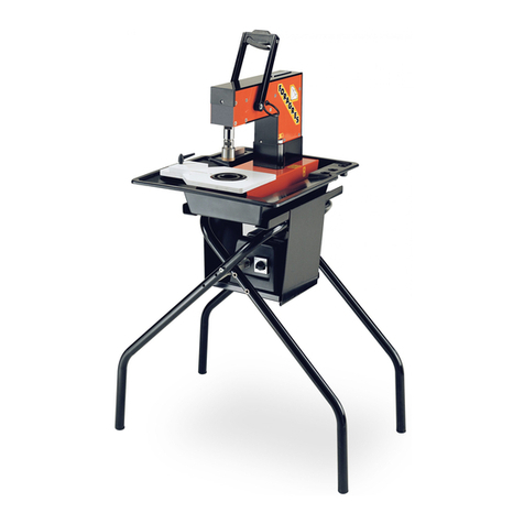
Battipav
Battipav Foragres User manual

Battipav
Battipav Super Pro 450 User manual

Battipav
Battipav LEGGERA 49 User manual

Battipav
Battipav SINTESI User manual

Battipav
Battipav VIP 850 User manual

Battipav
Battipav Extra 3300 Superlunga User manual

Battipav
Battipav Super Pro EVO 65 User manual

Battipav
Battipav PROFI EVO 6401EV User manual
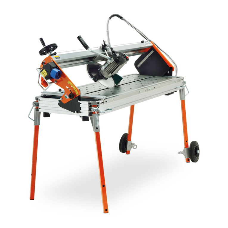
Battipav
Battipav CLASS plus User manual
