BFT PHEBE User manual

ISTRUZIONI D’USO E DI INSTALLAZIONE
INSTALLATION AND USER’S MANUAL
INSTRUCTIONS D’UTILISATION ET D’INSTALLATION
INSTALLATIONS-UND GEBRAUCHSANLEITUNG
INSTRUCCIONES DE USO Y DE INSTALACION
INSTRUÇÕES DE USO E DE INSTALAÇÃO
D811328 ver. 03 07-07-05
PHEBE
Via Lago di Vico, 44
36015 Schio (VI)
Tel.naz. 0445 696511
Tel.int. +39 0445 696533
Fax 0445 696522
Internet: www.bft.it
E-mail: [email protected]
I
GB
F
D
E
P
MOTORIZZAZIONE PER PORTE BASCULANTI A CONTRAPPESO
MOTOR DRIVES FOR COUNTER-BALANCED OVERHEAD DOORS
MOTORISATIONS POUR PORTES DE GARAGE A CONTREPOIDS
ANTRIEBE FÜR GEGENGEWICHT-GARAGENTORE
MOTORIZACION PARA PUERTAS BASCULANTES DE CONTRAPESOS
AUTOMATIZAÇÕES PARA PORTAS BASCULANTES COM CONTRAPESOS

2 - PHEBE Ver. 03
D811328_03
D811328_03
D811328_03
D811328_03

MANUALE D’USO ITALIANO
Nel ringraziarVi per la preferenza accordata a questo prodotto, la ditta è certa che
da esso otterrete le prestazioni necessarie al Vostro uso. Leggete attentamente
l’opuscolo “Avvertenze” ed il “Libretto istruzioni” che accompagnano que-
sto prodotto in quanto forniscono importanti indicazioni riguardanti la sicurezza,
l’installazione, l’uso e la manutenzione. Questo prodotto risponde alle norme
riconosciute della tecnica e della disposizioni relative alla sicurezza. Confermiamo
che è conforme alle seguenti direttive europee: 89/336/CEE, 73/23/CEE (e loro
modifiche successive).
1) GENERALITÀ
Progettato per motorizzare porte basculanti a contrappesi.
La compattezza e la versatilità di montaggio rendono la motorizzazione
applicabile in qualsiasi modello di basculante, sia a montaggio centrale che
laterale. È consigliato per uso residenziale.
Il riduttore di tipo irreversibile, mantiene la porta bloccata in chiusura senza
l’impiego di elettroserrature.
Nel caso manchi l’alimentazione di rete, lo sblocco si attiva dall’interno con
una apposita manopola. É dotato di microinteruttori che fermano il motore
sia in apertura che in chiusura e di luce di cortesia temporizzata.
2) SICUREZZA
L’automazione, se installata ed utilizzata correttamente, soddisfa il grado di sicu-
rezza richiesto. Tuttavia è opportuno osservare alcune regole di comportamento
per evitare inconvenienti accidentali.
Prima di usare l’automazione, leggere attentamente le istruzioni d’uso e conser-
varle per consultazioni future.
• Tenere bambini, persone e cose fuori dal raggio d’azione dell’automazione,
in particolare durante il funzionamento.
• Non lasciare radiocomandi o altri dispositivi di comando alla portata dei bambini
onde evitare azionamenti involontari dell’automazione.
• Non contrastare volontariamente il movimento dell’anta.
• Non tentare di aprire manualmentela porta se non è stato sbloccato l’at-
tuatore con l’apposita manopola di sblocco.
• Non modificare i componenti dell’automazione.
• In caso di malfunzionamento, togliere l’alimentazione, attivare lo sblocco
di emergenza per consentire l’accesso e richiedere l’intervento di un
tecnico qualificato (installatore).
• Per ogni operazione di pulizia esterna, togliere l’alimentazione di rete, e
se presente almeno un polo delle batterie.
• Tenere pulite le ottiche delle fotocellule ed i dispositivi di segnalazione
luminosa. Controllare che rami ed arbusti non disturbino i dispositivi di
sicurezza (fotocellule).
• Per qualsiasi intervento diretto all’automazione, avvalersi di personale
qualificato (installatore).
• Annualmente far controllare l’automazione da personale qualificato.
3) SBLOCCO MANUALE
Lo sblocco manuale o di emergenza va attivato quando si deve aprire manual-
mente la porta ed in ogni caso di non funzionamento o funzionamento anomalo
dell’automazione. Per eseguire la manovra di emergenza, bisogna:
• Accedere alla manopola di sblocco facendo scorrere il vano di copertura
C fino al suo arresto (Fig.1).
• Ruotare la manopola di sblocco di 90° in senso antiorario (Fig.1).
• Per ripristinare l’operazione motorizzata riposizionate la manopola nella
posizione originale.
4) SOTITUZIONE DELLA LAMPADINA
La sostituzione della lampadina luce di cortesia si effettua togliendo la
copertura trasparente (Fig.2).
ATTENZIONE: Utilizzare esclusivamente lampade tipo 24V 25W max
E14. Non rimuovere la guuaina di protezione “G” durante la sostituzione
della lampadina.
5) MANUTENZIONE E DEMOLIZIONE
La manutenzione dell’impianto va fatta eseguire regolarmente da parte di
personale qualificato. I materiali costituenti l’apparecchiatura e il suo imballo
vanno smaltiti secondo le norme vigenti.
AVVERTENZE
Il buon funzionamento dell’operatore è garantito solo se vengono rispettate
i dati riportati in questo manuale. La ditta non risponde dei danni causati
dall’inosservanza delle norme di installazione e delle indicazioni riportate
in questo manuale.
Le descrizioni e le illustrazioni del presente manuale non sono impegnative.
Lasciando inalterate le caratteristiche essenziali del prodotto, la Ditta si
riserva di apportare in qualunque momento le modifiche che essa ritiene con-
venienti per migliorare tecnicamente, costruttivamente e commercialmente
il prodotto, senza impegnarsi ad aggiornare la presente pubblicazione.
Fig. 1
Fig. 2
24V 25W
G
D811328_03
D811328_03
PHEBE Ver. 03 - 3
D811328_03
D811328_03

USER’S MANUAL
ENGLISH
Thank you for buying this product, our company is sure that you will be more
than satisfied with the product’s performance. The product is supplied with
a “Warnings” leaflet and an “Instruction booklet”. These should both be
read carefully as they provide important information about safety, installa-
tion, operation and maintenance. This product complies with the recognised
technical standards and safety regulations. We declare that this product
is in conformity with the following European Directives: 89/336/EEC and
73/23/EEC (and subsequent amendments).
1) GENERAL OUTLINE
This controller has been designed to motorize counter-balanced overhead
doors. The compactness and versatility of the installation allow the motor drive to
be fitted to almost any model of overhead door where it can be installed both in
the centre and at the side. It is particularly recommended for residential use.
The irreversible gearmotor keeps the door locked in the closing position
without electric lock.
In the case where the mains power supply is off, release is activated from
the inside by means of an appropriate knob. The release device if provided
with microswitches, which stop the motor both on opening and on closing,
and with a timed courtesy light.
2) SAFETY
If correctly installed and used, this automation device satisfies the required
safety level standards. However, it is advisable to observe some practical
rules in order to avoid accidental problems.
Before using the automation device, carefully read the operation instructions
and keep them for future reference.
• Keep children, persons and things outside the automation working area,
particularly during operation.
• Keep radio control or other control devices out of children’s reach, in
order to avoid any unintentional automation activation.
• Do not intentionally oppose the leaf movement.
• Do not attempt to open the gate by hand, if the actuator has not been
released by means of the appropriate release knob.
• Do not modify the automation components.
• In case of malfunction, disconnect the power supply, activate the emer-
gency release to gain access to the actuator and request the assistance
of a qualified technician (installer).
• Before proceeding to any external cleaning operation, disconnect the
mains powers supply and at least one of the battery pole, if fitted.
• Keep the photocell optical components and luminous signal indication
devices clean. Check that the safety devices (photocells) are not obscured
by branches or shrubs.
• For any direct assistance to the automation system, request the assistance
of a qualified technician (installer).
• Have qualified personnel check the automation system once a year.
3) MANUAL RELEASE
The manual or emergency release is to be activated when the door must
be opened manually, and any time the operator stops working or shows
malfunctions. To carry out the emergency manoeuvre, proceed as follows:
• Access the release knob by sliding its cover C until it stops (Fig.1).
• Rotate the release knob by 90° anticlockwise (Fig.1).
• To restore motor-driven operation, return the knob to its original posi-
tion.
4) BULB REPLACEMENT
To replace the courtesy light bulb, remove its transparent cover (Fig.2).
WARNING: Only 24V 25W max E14 bulbs must be used.
Do not remove protection sheath “G” while replacing the bulb.
5) MAINTENANCE AND DEMOLITION
The maintenance of the system should only be carried out by qualified
personnel regularly. The materials making up the set and its packing must
be disposed of according to the regulations in force.
WARNINGS
Correct controller operation is only ensured when the data contained
in the present manual are observed. The company is not to be held
responsible for any damage resulting from failure to observe
the installation standards and the instructions contained in the
present manual.
The descriptions and illustrations contained in the present manual are
not binding. The Company reserves the right to make any alterations
deemed appropriate for the technical, manufacturing and commercial
improvement of the product, while leaving the essential product fea-
tures unchanged, at any time and without undertaking to update the
present publication.
Fig. 1
Fig. 2
24V 25W
G
4 - PHEBE Ver. 03
D811328_03
D811328_03
D811328_03
D811328_03

MANUEL D’UTILISATION FRANÇAIS
Nous vous remercions pour avoir choisi ce produit. Nous sommes certains
qu’il vous offrira les performances que vous souhaitez. Lisez attentivement
la brochure “Avertissements” et le “Manuel d’instructions” qui accompa-
gnent ce produit, puisqu’ils fournissent d’importantes indications concernant
la sécurité, l’installation, l’utilisation et l’entretien. Ce produit est conforme
aux règles reconnues de la technique et aux dispositions de sécurité. Nous
certifions sa conformité avec les directives européennes suivantes: 89/336/
CEE, 73/23/CEE (et modifications successives).
1) GENERALITES
Motorisation conçue pour portes de garage à contrepoids.
La compacité et la facilité du montage rendent cette motorisation applica-
ble sur tous les modèles de porte de garage, tant à montage central que
latéral. Elle est conseillée pour l’emploi résidentiel. Le réducteur de type
irréversible bloque la porte en fermeture sans besoin d’utiliser de serrures
électriques.
En cas de faute d’électricité, on active le déblocage de l’intérieur avec une
poignée spécialement prévue. Il est doté de microinterupteurs qui arrêtent
le moteur tant en ouverture qu’en fermeture et d’une lumière de courtoisie
temporisée.
2) SECURITE
La motorisation, si installée et utilisée correctement, est conforme au degré
de sécurité demandé. Il est toutefois conseillé de respecter ces quelques
règles de conduite afin d’éviter tout inconvénient ou accident. Avant d’uti-
liser la motorisation, lire attentivement les instructions d’utilisation et les
conserver en cas de besoin.
• Tenir les enfants, les personnes et les choses hors du rayon d’action de
la motorisation, particulièrement pendant le fonctionnement.
• Ne pas laisser les radio commandes ou d’autres dispositifs de commande
à la portée des enfants, afin d’éviter des actionnements involontaires de
la motorisation.
• Ne pas contraster volontairement le mouvement du portail.
• Ne pas chercher à ouvrir manuellement le portail si l’actionneur n’a pas
été débloqué avec la poignée de déblocage spéciale.
• Ne pas modifier les composants de la motorisation.
• En cas de mauvais fonctionnement, couper l’alimentation, activer le dé-
blocage d’urgence afin de permettre l’accès et demander l’intervention
d’un technicien qualifié (installateur).
• Pour toute opération de nettoyage extérieur, couper l’alimentation de
ligne et, si présent, au moins un pôle des batteries.
• Nettoyer les optiques des cellules photoélectriques et les dispositifs de
signalisation lumineuse. S’assurer que des branches ou des arbustes ne
dérangent pas les dispositifs de sécurité (cellules photoélectriques).
• Pour toute intervention directe sur la motorisation, s’adresser à du per-
sonnel qualifié (installateur).
•
Chaque année, faire contrôler la motorisation par du personnel qualifié.
3) DEBLOCAGE MANUEL
Le déblocage manuel ou d’urgence doit être activé si on doit ouvrir la porte
manuellement et en tous les cas de non fonctionnement ou de mauvais fonc-
tionnement de l’automatisme. Pour effectuer la manœuvre d’urgence, il faut:
• Accéder à la poignée de déblocage en faisant coulisser la cache de
couverture C jusqu’à son arrêt (Fig. 1).
• Tourner la poignée de déblocage de 90° dans le sens contraire à celui
des aiguilles d’une montre (Fig. 1).
• Pour rétablir l’opération motoriste, replacer la poignée dans la position
originale.
4) REMPLACEMENT DE L’AMPOULE
Le remplacement de l’ampoule de la lumière de courtoisie se fait en enlevant
la couverture transparente (Fig. 2).
ATTENTION: Utiliser exclusivement des ampoules de type 24V 25W maxi
E14. Ne pas enlever la gaine de protection “G” pendant le remplacement
de l’ampoule.
5) ENTRETIEN ET DEMOLITION
L’entretien de l’installation doit être effectué régulièrement de la part de
personnel qualifié. Les matériaux constituant l’appareillage et son emballage
doivent être mis au rebut conformément aux normes en vigueur. Les piles
constituent des déchets spéciaux.
AVERTISSEMENTS
Le bon fonctionnement de l’actionneur n’est assuré que si les données
fournies dans ce manuel sont respectées. Le constructeur ne répond
pas pour les dommages provoqués par le non respect des normes
d’installation et des indications fournies dans ce manuel.
Les descriptions et les figures de ce manuel n’engagent pas le cons-
tructeur. En laissant inaltérées les caractéristiques essentielles du
produit, la Société se réserve le droit d’apporter à n’importe quel
moment les modifications qu’elle juge opportunes pour améliorer le
produit du point de vue technique, commercial et de construction, sans
s’engager à mettre à jour cette publication.
Fig. 1
Fig. 2
24V 25W
G
D811328_03
D811328_03
PHEBE Ver. 03 - 5
D811328_03
D811328_03

BEDIENUNGSANLEITUNG
DEUTSCH
Wir danken Ihnen, daß Sie sich für diese Anlage entschieden haben. Ganz sicher
wird sie mit ihren Leistungen Ihren Ansprüchen vollauf gerecht werden. Lesen
Sie aufmerksam die Broschüre “Hinweisen“ und die “Gebrauchsanweisung“
durch, die dem Produkt beiliegen. Sie enthalten wichtige Hinweise zur Si-
cherheit, Installation, Bedienung und Wartung der Anlage. Dieses Produkt
genügt den anerkannten technischen Regeln und Sicherheitsbestimmungen.
Wir bestätigen, daß es mit folgenden Europäischen Richtlinien übereinstimmt:
89/336/EWG, 73/23/EWG (und ihren nachfolgende Änderungen).
1) ALLGEMEINES
Zur Motorisierung von Gegengewichtschwingtoren entwickelter Antrieb.
Durch die kompakte Bauweise und die vielseitigen Montagemöglichkeiten
läßt sich der Antrieb an jede Art von Schwingtor anbringen. Dies gilt sowohl
für die Montage in der Mitte als auch an den Seiten des Tores. Dieses Modell
empfiehlt sich für die Anwendung an Wohngebäuden.
Der irreversible Getriebemotor hält die Torsperre in geschlossenem Zustand
ohne Elektroschloß aufrecht.
Wenn die Netzversorgung ausfällt, wird die Entsperrung von innen mit einem
speziellen Handgriff vollzogen. Er ist mit Mikroschaltern versehen, die den
Motor bei der Öffnung und Schließung stoppen. Ferner ist eine zeitgeschaltete
Hilfsbeleuchtung vorhanden.
2) SICHERHEIT
Die Anlage erfüllt bei richtiger Installation und Bedienung die erforderlichen
Sicherheitsstandards. Trotzdem ist es sinnvoll, einige Verhaltensmaßregeln zu
beachten, um unvorhergesehene Zwischenfälle auszuschließen.
Vor Gebrauch der Anlage die Betriebsanleitung aufmerksam lesen und für
zukünftige Einsichtnahme aufbewahren.
• Kinder, Erwachsene und Sachwerte sollten sich außerhalb des Wirkradius
der Anlage befinden, besonders während des Betriebes.
•
Keine Fernbedienungen oder andere Steuerungsvorrichtungen in Reichweite
von Kindern liegen lassen. Sie könnten die Anlage ungewollt in Gang setzen.
• Der Flügelbewegung nicht willentlich Kraft entgegensetzen.
• Nicht versuchen, das Tor von Hand zu öffnen, wenn nicht vorher der Antrieb
mit dem entsprechenden Entriegelungshandgriff entsperrt wurde.
• Keine Umbauten an Anlagenkomponenten vornehmen.
• Bei Betriebsstörungen die Stromversorgung unterbrechen, durch Betätigung
der Notfallentsperrung den Zugang ermöglichen und einen fachkundigen
Techniker (Installateur) hinzuziehen.
• Vor jeder Außenreinigung die Stromversorgung unterbrechen und - falls
vorhanden - zumindest einen Batteriepol abklemmen.
• Halten Sie die Optiken der Fotozellen und die Leuchtsignalvorrichtungen
sauber. Prüfen Sie, ob Äste oder Gesträuch die Sicherheitsvorrichtungen
beeinträchtigen können (Fotozellen).
• Wenn eine Arbeit unmittelbar an der Anlage erforderlich ist, wenden Sie sich
hierzu an fachkundiges Personal (Installateur).
• Die Anlage muß einmal jährlich von Fachpersonal kontrolliert werden.
3) HANDENTSPERRUNG
Die unter normalen Umständen oder im Notfall durchgeführte Entsperrung
von Hand ist zu aktivieren, wenn die Tür manuell geöffnet werden soll, auf
jeden Fall jedoch wenn die Antriebsanlage nicht oder nur gestört funktioniert.
Die Bedienung im Notfall geht folgendermaßen vonstatten:
• Indem man die Abdeckung C bis zum Anschlag verschiebt, erhält man
Zugang zum Entsperrgriff (Fig. 1).
• Der Handgriff wird um 90° gegen den Uhrzeigersinn gedreht (Fig. 1).
• Um den Motorbetrieb wieder aufzunehmen, wird der Handgriff in die
ursprüngliche Stellung zurückgebracht.
4) AUSTAUSCH DER BIRNE
Die Birne der Hilfsbeleuchtung wird ausgetauscht, indem man vorher die
Klarsichtabdeckung entfernt (Fig.2).
ACHTUNG: Verwenden Sie ausschließlich Birnen des Typs 24V 25W
max E14.Während die Birne ausgetauscht wird, darf der Schutzmantel “G”
nicht entfernt werden.
4) INSTANDHALTUNG UND VERSCHROTTUNG
Die Anlagenwartung ist regelmäßig von Fachleuten vorzunehmen. Die Ma-
terialien, aus denen die Apparatur besteht und ihre Verpackung sind vorschrifts-
mäßig zu entsorgen. Die Batterien dürfen nicht in die Umwelt gelangen.
HINWEISE
Der einwandfreie Betrieb des Antriebes ist nur dann garantiert, wenn die
Angaben aus diesem Handbuch beachtet werden. Der Hersteller haftet
nicht für Schäden, die durch Mißachtung der Installationsanweisungen
und der Angaben aus diesem Handbuch entstehen.
Die Beschreibungen und bildlichen Darstellungen in diesem Hand-
buch sind unverbindlich. Der Hersteller behält sich - ohne auch zur
Aktualisierung dieser Unterlagen verpflichtet zu sein - jederzeit vor,
Änderungen vornehmen, wenn er diese für technische oder bauliche
Verbesserungen als notwendig erachtet und die wesentlichen Produk-
teigenschaften unverändert bleiben.
Fig. 1
Fig. 2
24V 25W
G
6 - PHEBE Ver. 03
D811328_03
D811328_03
D811328_03
D811328_03

MANUAL DE USO ESPAÑOL
Al agradecerle la preferencia que ha manifestado por este producto, la empresa
está segura de que de él obtendrá las prestaciones necesarias para sus exigencias.
Lea atentamente el folleto “Advertencias” y el “Manual de instrucciones” que
acompañan a este producto, pues proporcionan importantes indicaciones referentes
a la seguridad, la instalación, el uso y el mantenimiento del mismo.
Este producto cumple los requisitos establecidos por las normas reconocidas
de la técnica y las disposiciones relativas a la seguridad. Confirmamos su
conformidad con las siguientes directivas europeas: 89/336/CEE, 73/23/CEE (y
modificaciones sucesivas).
1) DATOS GENERALES
Proyectado para motorizar puertas basculantes de contrapesos.
La compactibilidad y la versatilidad de montaje hacen la motorización aplicable
a cualquier modelo de basculante, tanto de montaje central como lateral. Es
aconsejable para uso residencial.
El reductor, de tipo irreversible, mantiene la puerta bloqueada cuando está cerrada
sin utilizar electrocerraduras.
En caso de que falte el suministro de corriente, el mecanismo de desbloqueo se
activa desde el interior con una manecilla expresamente prevista. El dispositivo
está dotado de microinterruptores, que paran el motor tanto en fase de apertura
como de cierre, y de luz interior temporizada.
2) SEGURIDAD
El automatismo, si se instala y utiliza correctamente, satisface el grado de seguridad
requerido. Sin embargo, es conveniente observar algunas reglas de comporta-
miento para evitar inconvenientes accidentales. Antes de usar el automatismo, lea
atentamente las instrucciones de uso y consérvelas para consultas futuras.
• Mantener a niños, personas y cosas fuera del campo de acción del automa-
tismo, especialmente durante su funcionamiento.
• No dejar radiomandos u otros dispositivos de mando al alcance de los niños,
para evitar el accionamiento involuntario del automatismo.
• No contrastar voluntariamente el movimiento de la hoja.
• No intentar abrir manualmente la cancela si antes no se ha desbloqueado el
servomotor con la manecilla de desbloqueo.
• No modificar los componentes del automatismo.
• En caso de mal funcionamiento, cortar el suministro de corriente, activar el
mecanismo de desbloqueo de emergencia para consentir el acceso y solicitar
la intervención de un técnico cualificado (instalador).
• Antes de realizar cualquier operación de limpieza externa, cortar el suministro
de corriente y, si está presente el kit de baterías tampón, desconectar al menos
un polo de las baterías.
• Mantener limpias las lentes de las fotocélulas y los dispositivos de señalización
luminosa. Controlar que ramas o arbustos no interfieran con los dispositivos
de seguridad (fotocélulas).
• Si resulta necesario efectuar una intervención directa en el automatismo,
llamar a personal cualificado (instalador).
•
Una vez al año, es preciso hacer controlar el automatismo por personal cualificado.
3) DESBLOQUEO MANUAL
El mecanismo de desbloqueo manual o de emergencia debe activarse cuando
se tenga que abrir manualmente la puerta y en todo caso de funcionamiento
inexistente o anómalo del automatismo. Para ejecutar la maniobra de emergencia,
es preciso:
• Acceder a la manecilla de desbloqueo haciendo correr el elemento de cobertura
C hasta su bloqueo (Fig. 1).
• Girar la manecilla de desbloqueo, dándole una vuelta de 90° en sentido con-
trario a las agujas del reloj (Fig. 1).
• Para restablecer la operación motorizada, hay que poner la manecilla en la
posición original.
4) SUSTITUCION DE LA BOMBILLA
La sustitución de la bombilla de la luz interior se efectúa quitando la cobertura
transparente (Fig. 2).
ATENCION: Deben utilizarse exclusivamente bombillas tipo 24 V 25 W máx. E14.
No quite la envoltura de protección “G” durante la sustitución de la bombilla.
5) MANTENIMIENTO Y DEMOLICION
El mantenimiento de la instalación debe ser realizado, con regularidad, por
personal cualificado. Los materiales que constituyen el equipo y su embalaje
deben eliminarse de conformidad con las normas vigentes.
ADVERTENCIAS
El buen funcionamiento del operador resulta garantizado únicamente si se
respetan los datos contenidos en este manual de instrucciones. La empresa
no responde de los daños causados por el incumplimiento de las normas
de instalación y de las indicaciones contenidas en este manual.
Las descripciones y las ilustraciones del presente manual tienen un carácter
puramente indicativo. Dejando inalteradas las características esenciales
del producto, la Empresa se reserva la posibilidad de aportar, en cualquier
momento, las modificaciones que considere convenientes para mejorar
técnica, constructiva y comercialmente el producto, sin la obligación de
poner al día esta publicación.
Fig. 1
Fig. 2
24V 25W
G
D811328_03
D811328_03
PHEBE Ver. 03 - 7
D811328_03
D811328_03

MANUAL PARA DE USO
PORTUGUÊS
Agradecendolhe pela preferência dada a este produto, a Empresa tem a
certeza que do mesmo obterá as prestações necessárias para o uso que
entende fazer. Leia atentamente o opúsculo “Recomendações” e o “ Manual
de instruções” que o acompanham, pois que esses fornecem indicações
importantes respeitantes a segurança, a instalação, o uso e a manutenção.
Este produto está em conformidade com as normas reconhecidas pela téc-
nica e pelas disposições relativas à segurança. Confirmamos que o mesmo
está em conformidade com as seguintes directivas europeias: 89/336/CEE,
73/23/CEE (e modificações sucessivas).
1) GENERALIDADES
Projectado para motorizar portas basculantes com contrapesos. A espes-
sura e a versatilidade de montagem tornam a motorização aplicável em a
qualquer modelo de basculante, seja de montagem central que lateral. É
aconselhado para o uso residencial. O redutor de tipo reversível, mantém a
porta bloqueada no fecho sem a utilização de fechaduras eléctricas.
No caso em que falte corrente eléctrica, o desbloqueio activa-se de den-
tro com um manípulo especial. Está equipado de microinterruptores que
param o motor quer na abertura que no fechamento e de luz de cortesia
temporizada.
2) SEGURANÇA
A automatização, se corretamente instalada e utilizada, satisfaz o grau de
segurança requerido.
Todavia, é conveniente observar algumas regras de comportamento para
evitar inconvenientes acidentais.
Antes de usar a automatização, ler cuidadosamente as instruções de uso
e conserválas para futuras consultas.
• Manter crianças,pessoas e coisas for a do raio de ação da automatização,
particularmente durante o funcionamento.
• Não deixar controles remotoss ou outros dispositivos de comando ao
alcance de crianças, de modo a evitar acionamentos involuntários da
auto-matização.
• Não contrastar propositalmente o movimento da folha do portão.
• Não tentar abrir manualmente o portão se não tiver sido ativado o desblo-
queio de emergência.
• Não modificar os componentes da automatização.
• Em caso de mau funcionamento, desligar a alimentação eléctrica, ati-
var o desbloqueio de emergência para consentir o acesso e solicitar a
presença de um técnico qualificado.
• Em toda operação de limpeza externa, desligar a alimentação eléctrica.
• Manter limpas: a guia de rolamento, as partes óticas das fotocélulas e
os dispositivos de sinalização luminosa. Verificar que ramos e arbustos
não atrapalhem os dispositivos de segurança (fotocélulas).
• Periodicamente, verificar a lubrificação da cremalheira.
• Em qualquer intervenção direta na automatização, valer-se de pessoal
qualificado (instalador).
• Anualmente fazer com que pessoal qualificado verifique a automatização.
3) DESBLOQUEIO MANUAL
O desbloqueio manual ou de emergência deve ser activado quando se deve
abrir a porta manualmente e em todo o caso de não funcionamento ou de
funcionamento anómalo da automatização. Para executar a manobra de
emergência, é preciso:
• Aceder ao manípulo de desbloqueio fazendo deslizar o vão de cobertura
C até que este se bloqueie (Fig.1).
• Girar o manípulo de desbloqueio de 90° no sentido anti-horário (Fig.1).
• Para restabelecer a operação motorizada colocar novamente o manípulo
na posição original.
4) SUBSTITUIÇÃO DA LÂMPADA
Para substituir a lâmpada da luz de cortesia deve-se retirar a cobertura
transparente (Fig.2).
ATENÇÃO: Utilizar exclusivamente lâmpadas do tipo 24V 25W max E14.
Não remover a bainha de protecção “G” durante a substituição da lâmpada.
5) MANUTENÇÃO E DEMOLIÇÃO
A manutenção da instalação deve ser executada periodicamente por
pessoal qualificado. Os materiais que constituem a aparelhagem e a sua
embalagem devem ser eliminados de acordo com a legislação vigente.
AVISOS
O bom funcionamento do operador é garantido, somente se forem
respeitados os dados contidos neste manual. A empresa não responde
por danos provocados pela inobservância das normas de instalação
e das indicações contidas neste manual.
As descrições e as ilustrações deste manual não constituem um
compromisso. Mantendo inalteradas as características essenciais
do produto, a Empresa reservase o direito de efectuar em qualquer
momento as modificações que julgar convenientes para melhorar as
características técnicas, de construção e comerciais do produto, sem
comprometerse em actualizar esta publicação.
Fig. 1
Fig. 2
24V 25W
G
8 - PHEBE Ver. 03
D811328_03
D811328_03
D811328_03
D811328_03

MANUALE PER L’INSTALLAZIONE ITALIANO
Nel ringraziarVi per la preferenza accordata a questo prodotto, la ditta è certa che
da esso otterrete le prestazioni necessarie al Vostro uso. Leggete attentamente
l’opuscolo “Avvertenze” ed il “Libretto istruzioni” che accompagnano questo
prodotto in quanto forniscono importanti indicazioni riguardanti la sicurez-
za, l’installazione, l’uso e la manutenzione. Questo prodotto risponde alle
norme riconosciute della tecnica e della disposizioni relative alla sicurezza.
Confermiamo che è conforme alle seguenti direttive europee: 89/336/CEE,
73/23/CEE (e loro modifiche successive).
1) SICUREZZA GENERALE
ATTENZIONE! Una installazione errata o un uso improprio del prodot-to,
può creare danni a persone, animali o cose.
• Leggete attentamente l’opuscolo ”Avvertenze” ed il ”Libretto istruzio-ni”
che accompagnano questo prodotto, in quanto forniscono Importanti indi-
cazioni riguardanti la sicurezza, l’installazione, l’uso e la manutenzione.
• Smaltire i materiali di imballo (plastica, cartone, polistirolo, ecc.) secon-do
quanto previsto dalle norme vigenti. Non lasciare buste di nylon e
polistirolo a portata dei bambini.
• Conservare le istruzioni per allegarle al fascicolo tecnico e per consul-
tazioni future.
• Questo prodotto è stato progettato e costruito esclusivamente per l’utilizzo
indicato in questa documentazione.
Usi non indicati in questa documentazione potrebbero essere fonte di
danni al prodotto e fonte di pericolo.
• La Ditta declina qualsiasi responsabilità derivante dall’uso improprio o
diverso da quello per cui è destinato ed indicato nella presente docu-
mentazione.
• Non installare il prodotto in atmosfera esplosiva.
• Gli elementi costruttivi della macchina devono essere in accordo con le
seguenti Direttive Europee: 89/336/CEE, 73/23/CEE, 98/37 CEE e loro
modifiche successive. Per tutti i Paesi extra CEE, oltre alle norme nazionali
vigenti, per un buon livello di sicurezza è opportuno rispettare anche le
norme sopracitate.
• La Ditta declina qualsiasi responsabilità dall’inosservanza della Buona
Tecnica nella costruzione delle chiusure (porte, cancelli, ecc.), nonché
dalle deformazioni che potrebbero verificarsi durante l’uso.
•
L’installazione deve essere in accordo con quanto previsto dalle Direttive
Europee: 89/336/CEE, 73/23/CEE,98/37 CEE e loro modifiche successive.
• Togliere l’alimentazione elettrica, prima di qualsiasi intervento sull’im-
pianto. Scollegare anche eventuali batterie tampone se presenti.
• Prevedere sulla rete di alimentazione dell’automazione, un interruttore
o un magnetotermico onnipolare con distanza di apertura dei contatti
uguale o superiore a 3,5 mm.
• Verificare che a monte della rete di alimentazione, vi sia un interruttore
differenziale con soglia da 0.03A.
• Verificare se l’impianto di terra è realizzato correttamente: collegare tutte
le parti metalliche della chiusura (porte, cancelli, ecc.) e tutti i componenti
dell’impianto provvisti di morsetto di terra.
• Applicare tutti i dispositivi di sicurezza (fotocellule, coste sensibili, ecc.)
necessari a proteggere l’area da pericoli di schiacciamento, convoglia-
mento, cesoiamento.
• Applicare almeno un dispositivo di segnalazione luminosa (lampeggiante)
in posizione visibile, fissare alla struttura un cartello di Attenzione.
• La Ditta declina ogni responsabilità ai fini della sicurezza e del buon
funzionamento dell’automazione se vengono impiegati componenti di
altri produttori.
•
Usare esclusivamente parti originali per qualsiasi manutenzione o riparazione.
• Non eseguire alcuna modifica ai componenti dell’automazione se non
espressamente autorizzata dalla Ditta.
• Istruire l’utilizzatore dell’impianto per quanto riguarda i sistemi di coman-do
applicati e l’esecuzione dell’apertura manuale in caso di emergenza.
• Non permettere a persone e bambini di sostare nell’area d’azione del-
l’automazione.
• Non lasciare radiocomandi o altri dispositivi di comando alla portata dei
bambini onde evitare azionamenti involontari dell’automazione.
• L’utilizzatore deve evitare qualsiasi tentativo di intervento o riparazione
dell’automazione e rivolgersi solo a personale qualificato.
• Tutto quello che non è espressamente previsto in queste istruzioni, non
è permesso.
• L’installazione deve essere fatta utilizzando dispositivi di sicurezza e
comandi conformi alla EN 12978.
2) GENERALITÀ
Progettato per motorizzare porte basculanti a contrappesi.
La compattezza e la versatilità di montaggio rendono la motorizzazione
applicabile in qualsiasi modello di basculante, sia a montaggio centrale che
laterale. È consigliato per uso residenziale.
Il riduttore di tipo irreversibile, mantiene la porta bloccata in chiusura senza
l’impiego di elettroserrature.
Nel caso manchi l’alimentazione di rete, lo sblocco si attiva dall’interno con
una apposita manopola. É dotato di finecorsa che arrestano il motore sia in
apertura che in chiusura e di luce di cortesia temporizzata.
Versioni disponibili:
PHEBE/PHEBE IP44
Versione con centralina (HYDRA) incorporata adatta a comandare uno o
due operatori.
PHEBE-SQ/PHEBE-SQ IP-44
Versione senza centralina di comando, indispensabile per automazioni con
due attuatori PHEBE di cui il primo è PHEBE, il secondo è PHEBE-SQ.
Possono essere impiegati anche quando interessa avere la centralina
montata a parete.
PHEBE C
Versione per basculanti a telo snodato con centralina (HYDRA) incorporata
adatta a comandare uno o due operatori.
PHEBE C-SQ
Versione per basculanti a telo snodato, senza centralina di comando,
indispensabile per automazioni con due attuatori PHEBE C di cui il primo
è PHEBE C, il secondo è PHEBE C-SQ. Possono essere impiegati anche
quando interessa avere la centralina montata a parete.
PHEBEKIT
Versione disponibile in kit; adatta per porte basculanti fino a 7m2 di telo,
dispone di centralina incorporata Mod. HYDRA.
ATTENZIONE: Gli operatori che non hanno la centralina a bordo, devono
essere comandati con una centralina dotata di regolazione elettronica di
coppia (serie HYDRA).
3) DATI TECNICI
Alimentazione: ..............................................................230V±10%50Hz (*)
Motore : .........................................................................24V 1500 min-1
Potenza motore: PHEBE/PHEBE-SQ IP44/PHEBE IP44: ...................40W
PHEBE C/PHEBE-C SQ IP44/PHEBE C IP44: ........45W
Classe isolamento: ................................................................................... F
Lubrificazione: .............................................................Grasso permanente
Rapporto di riduzione: ....................................................................... 1/812
Giri albero uscita: .................................................................. 1.8 min-1 MAX
Albero uscita: .................................................Albero cavo passante 20X20
Tempo apertura: .......................................................................... 17 ÷ 20 s
Coppia fornita: PHEBE/PHEBE-SQ IP44/PHEBE IP44: ................300Nm
PHEBE C/PHEBE-C SQ IP44/PHEBE C IP44: ....330 Nm
Limiti impiego: ...................................... 1 Motore X 7m2 / 2 Motori X 10m2
Reazione all’urto: .......................................... Limitatore di coppia integrato
su quadro di comando HYDRA
Finecorsa: ................................................... Elettrici incorporati e regolabili
Manovra manuale: ......................................................Sblocco a manopola
Numero manovre in 24 ore: .................................................................... 40
Luce di cortesia: ...............................................................24V ~ Max 25W
Temperatura di utilizzo: .............................................................. -15 +60° C
Grado di protezione:
PHEBE/PHEBE C: .............................................................................. IP30
PHEBE-SQ IP44/PHEBE IP44: .......................IPX4 (Parti elettriche:IP44)
Peso operatore: ..................................................................................10 kg
Dimensioni: ...................................................................................Vedi fig.1
(*) Tensioni speciali a richiesta
4) INSTALLAZIONE DELL’AUTOMAZIONE
Verifiche preliminari
Controllare:
• Che la struttura della porta sia sufficientemente robusta e rigida.
• Che la porta sia ben bilanciata.
• Che la porta scorra manualmente in modo regolare per tutta la corsa.
Se la porta non è di nuova installazione, controllare lo stato di usura di tutti
i componenti. Sistemare o sostituire le parti difettose o usurate.
L’affidabilità e la sicurezza dell’automazione è direttamente influenzata dallo
stato della struttura della porta basculante.
5) INSTALLAZIONE
5.1) Accessori necessari
•
Confezione bracci telescopici - Coppia tubi di trasmissione - Base di fissaggio.
5.2) Montaggio dell’attuatore (Fig.2)
• Fissare l’attuatore alla base di fissaggio con le quattro viti (A) in dotazione
e nella posizione più favorevole all’installazione (vedi quote fig.2).
NOTA: Si consiglia di applicare la copertura dell’attuattore solo ad in-
stallazione ultimata utilizzando le quattro viti B (Fig.2), questo consente
l’accesso al quadro comando ed alla regolazione dei fine corsa.
D811328_03
D811328_03
PHEBE Ver. 03 - 9
D811328_03
D811328_03

MANUALE PER L’INSTALLAZIONE
ITALIANO
• La posizione di fissaggio del l’attuatore varia secondo il tipo di basculante.
Nel caso di basculanti a contrappesi con guida verticale (fig.3) l’asse
dell’albero di trasmissione dell’attuatore, deve essere circa 70-80mm
più basso del fulcro “F” delle leve del telo esistenti.
• Nel caso di basculanti a guide verticali e orizzontali, l’asse dell’attuatore,
deve trovarsi circa 100-110mm più basso della metà dell’altezza totale
della porta (fig.4).
• Nel caso di basculanti con telo snodato utilizzare PHEBE-C. L’asse dell’attua-
tore, deve trovarsi circa 150mm più basso della cerniera snodo “C” (fig.5).
• Tagliare la base di fissaggio “B” in eccedenza rispetto al telo della porta
basculante (fig.3).
• Praticare i fori di fissaggio sulla base e fissarla al telo con il sistema più idonei
al tipo di basculante (viti, rivetti, ecc.). I punti di fissaggio devono trovarsi in
punti rinforzati del telo e possibilmente anche sotto il motore stesso.
5.3) Montaggio degli alberi di trasmissione
• Fissare i due supporti albero laterali “S” al telo (fig.6). Devono essere
fissati saldamente al telaio della porta basculante e perfettamente in
asse con il foro dell’albero dell’attuatore.
• Posizionare le boccole adattatrici albero “B” in entrambi i supporti “S” ed
infilare i tubi quadri di trasmissione “T” fino ad inserirli nella sede albero
“A” (fig.7) dell’attuatore.
• Tagliare le parti di albero eccedenti rispettando le misure riportate in fig.8
in cui “B” è il braccio e “C” è la cassa contrappesi.
5.4) Bilanciamento della porta basculante
• Eseguire l’apertura manuale della porta basculante. Se con l’attuatore
montato, la porta non è più bilanciata, (fig.9) aumentare il contrappeso
come segue.
• Togliere i carter delle casse contrappesi, sganciare i contrappesi ed aggiun-
gere pesi “P” (piatti in ferro) fino a ripristinare il bilanciamento della porta.
N.B. Se l’attuatore è montato in posizione centrale, aumentare i contrap-
pesi in modo equivalente.
• Se l’attuatore (singolo), è montato in posizione laterale, aggiungere più
peso dal lato dell’attuatore. L’installazione laterale è possibile solo se
il telaio della basculante, ha una struttura sufficientemente rigida da
cansentire di trasmettere il moto da un solo lato.
• Se i contrappesi sono in ferro fissare i pesi “P” con saldature (fig.9).
Se i contrappesi sono in altro materiale, fissare i pesi “P” nel modo più
idoneo.
5.5) Montaggio dei bracci telescopici
ATTENZIONE: Prima di far ruotare l’albero dell’attuatore, verificare
che le camme che comandano i micro-finecorsa, ruotino liberamente
(allentate).
1) Se la porta basculante presenta la misura riportata in fig.10 superiore a
15mm, si possono utilizzare i bracci telescopici diritti (fig.11).
2) Se tale misura (fig.10) è inferiore a 15mm, sono necessari bracci tele-
scopici curvi (fig.12).
3) Posizionare l’attacco superiore “A” (fig.13) di ciascun braccio in entrambi
i lati della basculante.
4) Le misure riportate nelle fig.13, sono indicative. Possono variare secondo
gli ingombri della porta.
5) Saldare gli attacchi bracci “A”; se già presenti nella basculante, verificare
se possono essere utilizzati con il tipo di bracci telescopici scelti.
6) Aprire completamente la basculante e misurare la distanza “D” (fig.14)
tra il foro dell’attacco “A” ed il centro dell’albero di trasmissione.
7) Tagliare il guidabraccio ed il braccio motore rispettando le misure indicate
in fig.15 (la quota D è la distanza ricavata precedentemente).
8) Se le quote riportate in fig.15, non si possono rispettare per insufficiente
lunghezza, verificare se, a porta chiusa, il braccio telescopico rimane
inserito per almeno 70-80mm (fig.16). In caso non si rispetti questa con-
dizione individuare una posizione dell’attacco “A” più idonea o adottare
dei bracci più lunghi.
9) Fissare il braccio telescopico all’attacco “A” (fig.17) con il perno e copiglia
in dotazione.
10)Incastrare gli alberi di trasmissione “T” (fig.18) nelle rispettive sedi quadre
dei bracci motore, forare completamente alberi e boccole e fissare con
viti passanti e dadi.
6) PREDISPOSIZIONE IMPIANTO ELETTRICO
AVVERTENZE - Nelle operazioni di cablaggio ed installazione riferirsi alle
norme vigenti e comunque ai principi di buona tecnica.
I conduttori alimentati con tensioni diverse, devono essere fisicamente
separati, oppure devono essere adeguatamente isolati con isolamento
supplementare di almeno 1mm.
I conduttori devono essere vincolati da un fissaggio supplementare in pros-
simità dei morsetti, per esempio mediante fascette.
6.1) Componenti principali per una automazione (fig.19):
I Interruttore onnipolare omologato con apertura contati di almeno
3,5 mm provvisto di protezione contro i sovraccarichi ed i corto
circuiti, atto a sezionare l’automazione dalla rete. Se non presente,
prevedere a monte dell’automazione un interruttore differenziale
omologato di adeguata portata e soglia da 0,03A.
M-Q-R Attuatore con centralina di comando e ricevente incorporata
CTBA Bracci telescopici e tubi di trasmissione.
Fr Fotocellula (ricevente)
Ft Fotocellula (trasmittente)
T Trasmittente 1-2-4 canali
CC Controllo costa sensibile
CS Costa sensibile
D Scatola derivazione
P Pulsantiera di comando interna
Predisporre l’impianto elettrico (fig.19) facendo riferimento alle norme vigenti
per gli impianti elettrici CEI 64-8, IEC364, armonizzazione HD384 o altre
norme nazionali. Tenere nettamente separati i collegamenti di alimentazione
di rete dai collegamenti di servizio (fotocellule, coste sensibili, dispositivi di
comando ecc.).
ATTENZIONE! Per il collegamento alla rete, utilizzare cavo multipolare
di sezione minima 3x1.5mm2 e del tipo previsto dalle normative vigenti.
A titolo di esempio, se il cavo è all’esterno (all’aperto), deve essere
almeno pari a H07RN-F mentre, se all’interno (in canaletta), deve essere
almeno pari a H05 VV-F con sezione 3x1.5mm2 .
6.2) Configurazioni e collegamenti
Rappresentazioni di collegamenti per le diverse configurazioni, sono riportate
in fig.20a-20b-20c-20d.
• Fig.20a 1 PHEBE o PHEBEKIT con centralina a bordo
• Fig.20b 1 PHEBE-SQ con centralina a parete.
• Fig.20c 2 PHEBE-SQ con centralina a parete mod.HYDRA.
• Fig.20d 1 PHEBE con centralina a bordo mod.HYDRA ed
1 PHEBE-SQ senza centralina.
6.3) Passaggio cavi
In fig.21, si evidenzia il passaggio dei cavi dell’attuatore. Il carter è provvisto
di pareti sottili da tagliare con forbice.
Se la basculante non è provvista di un fascione centrale dove poter passare
i cavi di collegamento (fig.21), prevedere appropriate canalette.
Il tratto di cavi tra parete e porta mobile, deve avere un’ansa “A” (fig.22)
sufficientemente lunga da permettere il movimento della porta senza essere
sottoposta a tensionamento.
7) REGOLAZIONE FINECORSA
Tolto il cofano superiore dell’attuatore, i micro di finecorsa con le rispettive
camme si trovano sulla sinistra dell’operatore.
Il micro superiore è il micro che comanda la fermata in chiusura (1) .
Il micro inferiore è il micro che comanda la fermata in apertura (2).
Nell’albero di uscita sono montate le due camme che comandano i micro. La
camma deve intercettare il comando del micro, sempre dalla parte opposta
alla testa della vite di fissaggio della camma stessa.
Le camme si regolano come segue:
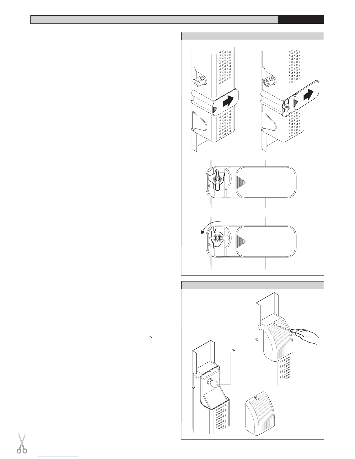
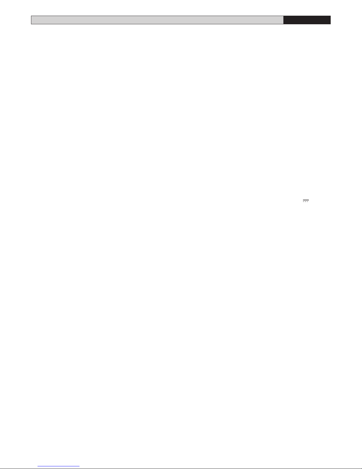
• Attivare lo sblocco manuale con l’apposita leva (fig.26).
• Chiudere completamente la porta (fig.23).
• Ruotare la camma di chiusura fino a sentire lo scatto del micro superiore
“1” e bloccarla in posizione avvitando la vite della camma.
• Aprire completamente la porta (fig.24).
• Ruotare la camma di apertura fino a sentire lo scatto del micro inferiore
“2” e bloccarla in posizione avvitando la vite della camma.
ATTENZIONE: Se le camme a fine manovra non intercettano i micro
di finecorsa, il motore continua a funzionare fino a quando termina
il tempo di lavoro impostato nella centralina (TW).
• Dare alimentazione al sistema e verificare la corretta posizione di chiusura
ed apertura. Eventualmente aggiustare la posizione delle camme quanto
basta.
• Verificare il fissaggio delle camme e rimontare il cofano superiore del-
l’attuatore.
8) QUADRO DI COMANDO
Per i collegamenti e le regolazioni della centralina, fare riferimento al manuale
istruzioni del quadro comando.
In fig.25a è riportata la morsettiera di collegamento per le versioni PHEBE-
SQ (versione senza centralina).
In fig.25b è riportata la morsettiera di collegamento per le versioni PHEBE.
Tenere nettamente separati i collegamenti di rete dai collegamenti in bassa
tensione.
10 - PHEBE Ver. 03
D811328_03
D811328_03
D811328_03
D811328_03

9) REGOLAZIONE DELLA FORZA DI SPINTA
ATTENZIONE: Verificare che il valore della forza d’impatto misurato
nei punti previsti dalla norma EN12445, sia inferiore a quanto
indicato nella norma EN 12453.
La regolazione di coppia del motore (antischiacciamento), viene regolata
dal quadro di comando. Vedere il manuale istruzione della centrale di co-
mando. La regolazione deve essere tarata per la minima forza necessaria
ad effettuare la corsa di apertura e chiusura completa e comunque entro i
limiti previsti dalle norme vigenti.
ATTENZIONE! Una regolazione di coppia eccessiva, può compromettere
la sicurezza antischiacciamento.
Al contrario, una regolazione di coppia insufficiente, può non garantire
una corsa di apertura o chiusura corretta.
10) SBLOCCO MANUALE
Lo sblocco manuale o di emergenza va attivato quando si deve aprire manual-
mente la porta ed in ogni caso di non funzionamento o funzionamento anomalo
dell’automazione. Per eseguire la manovra di emergenza, bisogna:
• Accedere alla manopola di sblocco facendo scorrere il vano di copertura
C fino al suo arresto (Fig.26).
• Ruotare la manopola di sblocco di 90° in senso antiorario (Fig.26).
• Per ripristinare l’operazione motorizzata riposizionate la manopola nella
posizione originale.
Nel caso la rimessa non disponga di di una entrata secondaria, è disponibile
uno sblocco esterno (Mod. SM1-2) applicabile alla cremonese della porta
(Fig. 27) che può comandare lo sblocco di uno o due motoriduttori.
Nel caso si monti lo sblocco dall’esterno, è necessario caricare la molla di
richiamo della leva di sblocco evidenziata in Fig.27 rif. A.
11) VERIFICA DELL’AUTOMAZIONE
Prima di rendere definitivamente operativa l’automazione, controllare scru-
polosamente quanto segue:
• Verificare che tutti i componenti siano fissati saldamente.
• Controllare il corretto funzionamento di tutti i dispositivi di sicurezza
(fotocellule, costa pneumatica, ecc).
• Verificare il comando della manovra di emergenza.
• Verificare l’operazione di apertura e chiusura con i dispositivi di comando
applicati.
• Verificare la logica elettronica di funzionamento normale (o personalizzata)
nella centralina di comando.
12) USO DELL’AUTOMAZIONE
Poichè l’automazione può essere comandata a distanza mediante radioco-
mando o pulsante di Start, è indispensabile controllare frequentemente la
perfetta efficienza di tutti i dispositivi di sicurezza.
Per qualsiasi anomalia di funzionamento, intervenire rapidamente avvalendosi
di personale qualificato.
Si raccomanda di tenere i bambini a debita distanza dal raggio d’azione
dell’automazione.
13) COMANDO
L’utilizzo dell’automazione consente l’apertura e la chiusura della porta in
modo motorizzato. Il comando può essere di diverso tipo (manuale, con
radiocomando, controllo accessi con badge magnetico, ecc.) secondo le
necessità e le caratteristiche dell’installazione. Per i vari sistemi di comando,
vedere le relative istruzioni.
Gli utilizzatori dell’automazione devono essere istruiti al comando e al-
l’uso.
14) MANUTENZIONE
Per qualsiasi manutenzione all’automazione, togliere alimentazione.
L’attuatore non richiede manutenzioni periodiche. Controllare eventualmente
il serraggio delle viti di fissaggio e l’ingrassaggio dei bracci telescopici.
• Verificare i dispositivi di sicurezza della porta e della motorizzazione.
• Controllare periodicamente la forza di spinta ed eventualmente correggere
la posizione di coppia elettrica nella centralina.
• Per qualsiasi anomalia di funzionamento non risolta, togliere alimentazione
al sistema e chiedere l’intervento di personale qualificato (installatore).
Nel periodo di fuori servizio, attivare lo sblocco manuale per consentire
l’apertura e la chiusura manuale.
15) INCONVENIENTI E RIMEDI
15.1) Funzionamento difettoso del motoriduttore
• Verificare con apposito strumento la presenza di tensione ai capi del
motoriduttore dopo il comando di apertura o chiusura.
MANUALE PER L’INSTALLAZIONE ITALIANO
Se il motore vibra ma non gira, può essere:
• se il movimento dell’anta, è contrario a quello che dovrebbe essere,
invertire i collegamenti di marcia del motore.
• FINE CORSA; può succedere che la porta non completi la corsa o che il
motore funzioni anche dopo che la porta è arrivata a finecorsa. Verificare
la posizione delle camme che comandano i finecorsa.
15.2) Funzionamento difettoso degli accessori elettrici
Tutti i dispositivi di comando e di sicurezza, in caso di guasto, possono causare
anomalie di funzionamento o blocco dell’automazione stessa.
Per individuare il guasto, è opportuno scollegare uno ad uno tutti i dispo-
sitivi dell’automazione, fino ad individuare quello che causa il difetto. Dopo
averlo riparato o sostituito, ripristinare tutti i dispositivi precedentemente
scollegati. Per tutti i dispositivi installati, fare riferimento al rispettivo manuale
istruzione.
16) RUMOROSITÀ
Il rumore aereo prodotto dal motoriduttore in condizioni normali di utilizzo è
costante e non supera i 70dB(A).
17) DEMOLIZIONE
L’eliminazione dei materiali va fatta rispettando le norme vigenti.
Nel caso di demolizione dell’automazione non esistono particolari pericoli
o rischi derivanti dall’automazione stessa.
È opportuno in caso, di recupero dei materiali, che vengano separati per
tipologia (parti elettriche - rame - alluminio - plastica - ecc.).
18) SMANTELLAMENTO
Nel caso l’automazione venga smontata per essere poi rimontata in altro
sito, bisogna:
• Togliere l’alimentazione e scollegare tutto l’impianto elettrico.
• Togliere il motoriduttore dalla base di fissaggio.
• Smontare il quadro di comando se separato e tutti i componenti dell’in-
stallazione.
• Nel caso alcuni componenti non possano essere rimossi o risultino
danneggiati, provvedere alla loro sostituzione.
AVVERTENZE
Il buon funzionamento dell’attuatore è garantito solo se vengono
rispettati i dati riportati in questo manuale.
La ditta non risponde dei danni causati dall’inosservanza delle norme
di installazione e delle indicazioni riportate in questo manuale.
Le descrizioni e le illustrazioni del presente manuale non sono impe-
gnative. Lasciando inalterate le caratteristiche essenziali del prodotto,
la Ditta si riserva di apportare in qualunque momento le modifiche che
essa ritiene convenienti per migliorare tecnicamente - costruttivamente
e commercialmente il prodotto, senza impegnarsi ad aggiornare la
presente pubblicazione.
D811328_03
D811328_03
PHEBE Ver. 03 - 11
D811328_03
D811328_03

INSTALLATION MANUAL
ENGLISH
Thank you for buying this product. Our company is sure that you will be more
than satisfied with the product’s performance.
Carefully read the “WARNINGS” pamphlet and the “INSTRUCTION
BOOKLET” which are supplied together with this product, since they provide
important information regarding the safety, installation, use and maintenance
of the product. This product complies with recognised technical standards
and safety regulations. We declare that this product is in conformity with the
following European Directives: 89/336/EEC, 73/23/EEC and subsequent
amendments.
1) GENERAL SAFETY
WARNING! An incorrect installation or improper use of the product
can cause damage to persons, animals or things.
• The “Warnings” leaflet and “Instruction booklet” supplied with this
product should be read carefully as they provide important information
about safety, installation, use and maintenance.
• Scrap packing materials (plastic, cardboard, polystyrene etc) according
to the provisions set out by current standards. Keep nylon or polystyrene
bags out of children’s reach.
• Keep the instructions together with the technical brochure for future
reference.
• This product was exclusively designed and manufactured for the use
specified in the present documentation. Any other use not specified in
this documentation could damage the product and be dangerous.
• The Company declines all responsibility for any consequences result-
ing from improper use of the product, or use which is different from that
expected and specified in the present documentation.
• Do not install the product in explosive atmosphere.
• The construction components of this product must comply with the following
European Directives: 89/336/CEE, 73/23/EEC, 98/37/EEC and subse-
quent amendments. As for all non-EEC countries, the above-mentioned
standards as well as the current national standards should be respected
in order to achieve a good safety level.
• The Company declines all responsibility for any consequences resulting
from failure to observe Good Technical Practice when constructing clos-
ing structures (door, gates etc.), as well as from any deformation which
might occur during use.
• The installation must comply with the provisions set out by the following
European Directives: 89/336/CEE, 73/23/EEC, 98/37/EEC and subsequent
amendments.
• Disconnect the electrical power supply before carrying out any work on
the installation. Also disconnect any buffer batteries, if fitted.
• Fit an omnipolar or magnetothermal switch on the mains power supply,
having a contact opening distance equal to or greater than 3,5 mm.
• Check that a differential switch with a 0.03A threshold is fitted just before
the power supply mains.
• Check that earthing is carried out correctly: connect all metal parts for
closure (doors, gates etc.) and all system components provided with an
earth terminal.
• Fit all the safety devices (photocells, electric edges etc.) which are needed
to protect the area from any danger caused by squashing, conveying and
shearing.
• Position at least one luminous signal indication device (blinker) where it
can be easily seen, and fix a Warning sign to the structure.
•
The Company declines all responsibility with respect to the automation safety
and correct operation when other manufacturers’ components are used.
• Only use original parts for any maintenance or repair operation.
• Do not modify the automation components, unless explicitly authorised
by the company.
• Instruct the product user about the control systems provided and the
manual opening operation in case of emergency.
• Do not allow persons or children to remain in the automation operation
area.
• Keep radio control or other control devices out of children’s reach, in
order to avoid unintentional automation activation.
• The user must avoid any attempt to carry out work or repair on the automa-
tion system, and always request the assistance of qualified personnel.
• Anything which is not expressly provided for in the present instructions,
is not allowed.
• Installation must be carried out using the safety devices and controls
prescribed by the EN 12978 Standard.
2) GENERAL OUTLINE
This controller has been designed to motorize counter-balanced overhead
doors.
The compactness and versatility of the installation allow the motor drive to be
fitted to almost any model of overhead door where it can be installed both in the
centre and at the side. It is particularly recommended for residential use.
The irreversible gearmotor keeps the door locked in the closing position
without electric lock.
In the case where the mains power supply is off, release is activated from
the inside by means of an appropriate knob. The release device if provided
with microswitches, which stop the motor both on opening and on closing,
and with a timed courtesy light.
The following versions are available:
PHEBE/PHEBE IP44
Model with built-in control unit (HYDRA) controlling one or two controllers.
PHEBE-SQ/PHEBE-SQ IP-44
Model without control unit indispensable for automations with two controllers
PHEBE, the first of which is PHEBE and the second is PHEBE-SQ. They
can be also used in case of wall-mounted control unit.
PHEBE C
Version for articulated-panel overhead doors with an incorporated control
unit (HYDRA) suitable for controlling one or two operators.
PHEBE C-SQ
Version for articulated-panel overhead doors without a control unit, indis-
pensable for automation systems with two PHEBE actuators, the first being
PHEBE C and the second PHEBE C-SQ. These can also be used when the
control unit is to be wall-mounted.
PHEBEKIT
Model available in kit used for overhead doors with a door panel of up to
7m2. It is equipped with a built-in control unit Mod. HYDRA.
CAUTION - The controllers without pre-assembled control unit, must be
controlled by a control unit featuring electronic torque adjustment (series
HYDRA).
3) TECHNICAL SPECIFICATIONS
Power supply: ...............................................................230V±10%50Hz (*)
Motor: ............................................................................24V 1500 min-1
Motor Power:PHEBE/PHEBE-SQ IP44/PHEBE IP44: ......................... 40W
PHEBE C/PHEBE-C SQ IP44/PHEBE C IP44: ........45W
Insulation class: ........................................................................................ F
Lubrication: .................................................................... Permanent grease
Reduction ratio: .................................................................................. 1/812
Output shaft revolutions: ......................................................1.8 min-1 MAX
Output shaft: ............................................... Shaft with through wire 20X20
Opening time: ............................................................................... 17 - 20 s
Torque supplied: PHEBE/PHEBE-SQ IP44/PHEBE IP44: ..............300 Nm
PHEBE C/PHEBE-C SQ IP44/PHEBE C IP44: ...330 Nm
Operation limits: ...............................1 Motor X 7sqm / 2 Motors X 10sqm
Impact reaction: .................................................... Integrated torque limiter
on HYDRA control panel
Limit switches: .................................. Electric, incorporated and adjustable
Manual manoeuvre: ............................................................... Knob release
Number of manoeuvres in 24 hours: ...................................................... 40
Courtesy light: ...................................................................24V ~ Max 25W
Working temperature: .............................................................. -15 +60° C
Degree of protection
PHEBE/PHEBE C: .............................................................................. IP30
PHEBE-SQ IP44/PHEBE IP44: ...........IPX4 (Electrical components:IP44)
Operator weight: .................................................................................10 kg
Dimensions: .................................................................................. See fig.1
(*) Special voltages on request
4) INSTALLATION OF THE AUTOMATION
Preliminary checks
Check:
• that the structure of the door is sturdy and strong enough
• that the door is properly balanced
• that the door can be slid manually and runs smoothly along the whole of
its stroke
If the door being installed is not new, check whether its components are worn.
Repair or replace any worn or damaged parts.
Automation reliability and safety are directly influenced by the condition of
the overhead door structure.
5) INSTALLATION
5.1) Required accessories:
Telescopic arm kit - Pair of driving pipes - Fixing base
5.2) Actuator fitting (Fig.2)
• Secure the actuator to the fixing base by means of the four screws (A)
supplied, finding the most favourable position for installation (see dimen-
12 - PHEBE Ver. 03
D811328_03
D811328_03
D811328_03
D811328_03

INSTALLATION MANUAL ENGLISH
sions in fig.2).
NOTE: It is advisable to fit the actuator cover only after completing the
installation, using the four screws (B) (Fig.2); this makes it possible to
access the control panel and to adjust the limit switches.
• The fixing position of the actuator changes according to the type of over-
head door. In the case of counter-balanced overhead doors with vertical
guide (fig. 3) the axis of the actuator driving shaft, must be about 70-80
mm lower than the fulcrum “F” of the already existing panel levers.
• For overhead doors with vertical and horizontal guides, the axis of the
actuator must be about 100-110 mm lower than half the total height of
the door (fig. 4).
• In the case of articulated-panel overhead doors, use PHEBE-C. The
actuator axis must be positioned about 150mm lower than the articulated
hinge “C” (fig.5).
• Remove the fixing base surplus “B” exceeding the overhead door panel
(fig. 3).
• Make some fixing holes in the base and secure it to the panel using
fasteners suited to the type of overhead door (screws, rivets etc.). The
fixing points must be made in reinforced points of the panel and, if pos-
sible, under the motor.
5.3) Driving shaft assembly
• Fasten the two side shaft supports “S” to the panel (fig. 6).These should
be fastened securely to the frame of the overhead door and should be
perfectly aligned with the actuator shaft hole.
• Position the shaft adaptor bushes “B” in both the supports “S” and insert
the square driving pipes “T” until they enter the housing of the actuator
shaft “A” (fig. 7).
• Cut the shaft surplus in keeping with the measurements given in fig. 8
where “B” is the and “C” is the counter-weight case.
5.4) Balancing of overhead door
• Carry out the manual opening of the overhead door. If when the actuator
is installed, the door is no longer balanced (fig. 9), increase the counter-
weighting as follows:
• Remove the guards of the counter-weight cases, release the counter-
weights and add weights “P” (iron plates) until the balancing of the door
is achieved.
N.B. If the actuator is installed in a central position, increase the counter-
weights in an equal amount.
• If the (single) actuator is installed at the side, add more weight to the
actuator side.The lateral installation is possible provided that the structure
of the overhead door panel is strong enough to transmit the movement
from one side only.
• If the counter-weights are made of iron, fasten the weights “P” by weld-
ing (fig. 9). If the counter-weights are made of other materials, fasten the
weights “P” in the most appropriate way.
5.5) Telescopic arm assembly
WARNING: Before rotating the actuator shaft, check that the cams
controlling the microswitches - limit switches rotate freely (loose).
1) If the overhead door measurement shown in fig. 10, is 15 mm or more,
fit the straight telescopic arms (fig. 11).
2) If the overhead door measurement (fig. 10) is less than 15 mm, fit the
curved telescopic arms (fig. 12).
3) Position the upper fastener “A” (fig. 13) of each arm on both sides of the
overhead door.
4) The dimensions given in fig. 13 are merely indicative. They may vary
according to the overall dimensions of the door.
5) Weld the arm fasteners “A” Some overhead door models may already
have the fasteners “A” attached. In this case, check if they can be used
for the type of telescopic arms selected.
6) Open the overhead door completely and measure the distance D
(fig. 14) between the fastener hole “A” and the centre of the driving
shaft.
7) Cut the arm guide and the driving arm in keeping with the measurements
indicated in fig. 15 (value “D” is the distance previously obtained).
8) If the values given in fig. 15 cannot be observed because the telescopic
arm length is insufficient, check when the door is closed whether the
telescopic arm stays inserted for at least 70-80 mm (fig. 16). If this is not
the case, find a position more suitable for the fastener “A” or use longer
arms.
9) Secure the telescopic arm onto the fastener “A” (fig. 17) using the pin
and split pin supplied.
10)Insert the driving shafts “T” (fig. 18) in the corresponding square housings
of the driving arms, make through holes in the shafts and bushes and
fasten using through screws and nuts.
6) ELECTRICAL PLANT SET-UP
WARNINGS - For wiring and installation operations, refer to the current
standards and good technical principles.
Wires powered at different voltages must be physically separated, or suitably
insulated with at least 1 mm extra insulation. The wires must be clamped by
an extra fastener near the terminals, for example by bands.
6.1) Main components for one automation (fig. 19):
I Type approved omnipolar switch with 3,5 mm min. contact opening
provided with overload and short-circuit protection, used to break the
automation connection from the mains. If not present, provide the
automation with a type approved differential switch with adequate
capacity and a 0.03 A threshold.
M-Q-R) Actuator with control unit with built-in receiver
CTBA) Telescopic arms and transmission pipes
Fr) Photocell (receiver)
Ft) Photocell (transmistter)
T) 1-2-4 channel transmitter
CC) Sensitive edge check
CS) Sensitive edge
D) Connector block
P) Internal control push button strip
Set the electrical plant (fig. 19) according to the current standards for elec-
trical plants CEI 64-8, IEC364, Harmonization HD384 and other national
regulations. Keep the power supply connections definitely separated from
the auxiliary connections (photocells, sensitive edges, control devices,
etc.).
WARNING! For connection to the mains, use a multipolar cable with
a minimum of 3x1.5mm2 cross section and complying with the previ-
ously mentioned regulations. For example, if the cable is out side (in
the open), it has to be at least equal to H07RN-F, but if it is on the inside
(or outside but placed in a plastic cable cannel) it has to be or at least
egual to H05VV-F with section 3x1.5mm2.
6.2) Connection arrangement
Fig. 20a-20b-20c-20d
show some examples of connections for the different arrangements.
Fig. 20a One PHEBE or PHEBEKIT with pre-assembled control unit
Fig. 20b One PHEBE-SQ with wall-mounted control unit
Fig. 20c Two PHEBE-SQ with wall-mounted control unit mod. HYDRA
Fig. 20d One PHEBE with pre-assembled control unit mod. HYDRA and
one PHEBE-SQ without control unit.
6.3) Cable passage
Fig. 21 shows the passage of the actuator cables. The casing features thin
walls to be cut using a pair of scissors.
If the overhead door is not provided with a central element where to pass
the connection cables (fig. 21), apply appropriate raceways.
The part of the cables between the wall and mobile door should form a
loop “A” (fig. 22) long enough to allow the movement of the door without
tensioning.
7) LIMIT SWITCH ADJUSTMENT
Remove the upper casing of the gearmotor, the limiting microswitches with
the corresponding cams are located on the left of the controller.
The upper microswitch controls stopping in the closing position “1”.
The lower microswitch controls stopping in the opening position “2”.
The two cams which control the microswitches are fitted to the output
shaft.
The cam should detect the microswitch command always on the side op-
posite to the fixing screw head of the cam.
The cams should be adjusted as follows:
Operate the manual release using the appropriate lever (fig. 26).
Close the door completely (fig. 23).
Turn the closing cam until the triggering of the upper microswitch “1” can be
heard and lock the cam in position by tightening the cam screw.
Open the door completely (fig. 24).
Turn the opening cam until the triggering of the lower microswitch “2” can be
heard and lock the cam in position by tightening the cam screw.
CAUTION: If the cams at the end of the manoeuvre do not intercept the
limiting microswitch, the motor will continue to run until the time set
on the control unit (TW) has elapsed.
Supply the system with power and check that the closing and opening posi-
tions are correct. If necessary adjust the cam position as required.
Make sure the cams are properly fastened and re-fit the upper casing of
the actuator.
D811328_03
D811328_03
PHEBE Ver. 03 - 13
D811328_03
D811328_03

INSTALLATION MANUAL
ENGLISH
8) CONTROL UNIT
For the connections and adjustment of the control unit, see the specific
instruction manual.
Fig. 25a shows the connection terminal board for the version PHEBE-SQ
(version without control unit).
Keep the low voltage connections definitely separated form the power sup-
ply connections.
9) MOTOR TORQUE ADJUSTMENT
WARNING: Check that the impact force value measured at the
points established by the EN 12445 standard is lower than that
specified in the EN 12453 standard.
The adjustment of the motor torque (anti-squashing) is performed on the
control panel. See control unit instruction manual.
The adjustment should be set for the minimum force required to carry out
the opening and closing strokes completely observing, however, the limits
of the relevant standards in force.
CAUTION! Excessive torque adjustment may jeopardise the anti-squash
safety function. On the other hand insufficient torque adjustment may
not guarantee correct opening or closing strokes.
10) EMERGENCY MANOUVRE
The manual or emergency release is to be activated when the door must be
opened manually, and any time the operator stops working or shows malfunc-
tions. To carry out the emergency manoeuvre, proceed as follows:
• Access the release knob by sliding its cover C until it stops (Fig.26).
• Rotate the release knob by 90° anticlockwise (Fig.26).
• To restore motor-driven operation, return the knob to its original posi-
tion.
If the garage does not have a secondary access door, an external release
mechanism is provided (Mod. SM1-2) which can be fitted to the door cre-
mone bolt (fig. 27). Such a mechanism can activate the release of one or
two gearmotors.
If the release is fitted on the outside, then the return spring of the release
lever shown in fig. 27 must be loaded.
11) CHECKING THE AUTOMATION
Before considering the automation completely operational, the following
checks must be made with great care:
Check that all components are properly fastened.
Check that all the safety means work properly (i.e. photocells, pneumatic
rubber skirt, etc.).
Check the emergency manoeuvre function.
Check the opening and closing manoeuvres using the controls.
Check the control unit’s electronic logic in normal or customised operation
in the control unit.
12) USE OF THE AUTOMATION
Since the automation may be remote controlled either by radio or a start
button, it is essential that all safety means are checked frequently.
Any malfunction should be corrected immediately by qualified person-
nel.
Keep children at a safe distance from the field of action of the automa-
tion.
13) THE CONTROLS
With the automation the door has a power driven opening and closing. The
controls can come in various forms (i.e. manual, remote controlled, limited
access by magnetic badge, etc.) depending on needs and installation
characteristics. For details on the various command systems, consult the
specific instruction booklets.
Anyone using the automation must be instructed on its operation and
controls.
14) MAINTENANCE
All maintenance operations must be performed with the system power
supply shut off.
The actuator does not require periodical maintenance operations. If neces-
sary, check that the screws are properly tightened and that the telescopic
arms are adequately greased.
Check the safety devices of the door and motor drive.
Check the pushing force periodically. If necessary, adjust the position of the
electric torque in the control unit.
For any malfunction that remains unsolved, shut off the power to the system
and call a qualified specialist (installer). When the automation is out of order,
activate the manual release to allow manual opening and closing.
15) TROUBLESHOOTING
15.1) Faulty operation of the gearmotor
Use a suitable instrument to check if there is a voltage across the gearmotor
terminals when an open or close command has been given.
If the motor vibrates but does not turn, this may be due to:
the common wire C is wrongly connected (it is always light blue) the drive
capacitor is not connected to the terminals in the control unit if the leaf
moves in the wrong direction, invert the drive connections of the motor in
the control unit
LEAF STOP: the door may not complete its stroke or the motor may continue
to run after the door has reached the stop position. Check the position of the
cams controlling the limit switches.
15.2) Faulty operation of the electrical accessories
If any of the control and safety components are faulty, this can cause mal-
functions or a breakdown of the whole automation.
In case of a fault, it is wise to disconnect each of the components in the
automation one at a time, until the one that is causing the fault is found.
After having repaired or replaced it, restore all the components that were
disconnected. For details on each component, refer to its specific instruc-
tion manual.
16) NOISE
The aerial noise produced by the gearmotor under normal operating condi-
tions is constant and does not exceed 70dB(A).
17) SCRAPPING
Materials must be disposed of in conformity with the current regulations.
In case of scrapping, the automation devices do not entail any particular
risks or danger. In case of recovered materials, these should be sorted out
by type (electrical components, copper, aluminium, plastic etc.).
18) DISMANTLING
When the automation system is disassembled to be reassembled on another
site, proceed as follows:
• Disconnect the power supply and the entire electrical installation.
• Remove the gearmotor from its fixing base.
• Disassemble the control panel, if separate, and all installation compo-
nents.
• In the case where some of the components cannot be removed or are
damaged, they must be replaced.
WARNINGS
Correct controller operation is only ensured when the data contained
in the present manual are observed. The company is not to be held
responsible for any damage resulting from failure to observe
the installation standards and the instructions contained in the
present manual.
The descriptions and illustrations contained in the present manual are
not binding. The Company reserves the right to make any alterations
deemed appropriate for the technical, manufacturing and commercial
improvement of the product, while leaving the essential product
features unchanged, at any time and without undertaking to update
the present publication.
14 - PHEBE Ver. 03
D811328_03
D811328_03
D811328_03
D811328_03

MANUEL D’INSTALLATION FRANÇAIS
Nous vous remercions pour avoir choisi ce produit. Nous sommes certains
qu’il vous offrira les performances que vous souhaitez.
Lisez attentivement la brochure “AVERTISSEMENTS” et le “MANUEL
D’INSTRUCTIONS” qui accompagnent ce produit, puisqu’ils fournissent
d’importantes indications concernant la sécurité, l’installation, l’utilisation
et l’entretien. Ce produit est conforme aux règles reconnues de la techni-
que et aux dispositions de sécurité. Nous certifions sa conformité avec les
directives européennes suivantes: 89/336/CEE, 73/23/CEE et modifications
successives.
1) SECURITE GENERALE
ATTENTION! Une installation erronée ou une utilisation impropre du
produit peuvent provoquer des lésions aux personnes et aux ani-
maux ou des dommages aux choses.
• Lisez attentivement la brochure “Avertissements” et le “Manuel d’ins-
tructions” qui accompagnent ce produit, puisqu’ils fournissent d’im-
portantes indications concernant la sécurité, l’installation, l’utilisation et
l’entretien.
• Eliminer les matériaux d’emballage (plastique, carton, polystyrène etc.)
selon les prescriptions des normes en vigueur. Ne pas laisser des enve-
loppes en nylon et polystyrène à la portée des enfants.
• Conserver les instructions et les annexer à la fiche technique pour les
consulter à tout moment.
• Ce produit a été conçu et réalisé exclusivement pour l’utilisation indi-
quée dans cette documentation. Des utilisations non indiquées dans
cette documentation pourraient provoquer des dommages au produit et
représenter une source de danger pour l’utilisateur.
• La Société décline toute responsabilité dérivée d’une utilisation impropre
ou différente de celle à laquelle le produit a été destiné et qui est indiquée
dans cette documentation.
• Ne pas installer le produit dans une atmosphère explosive.
• Les éléments constituant la machine doivent être conformes aux Di-
rectives Européennes suivantes: 89/336/CEE, 73/23/CEE, 98/37 CEE
et modifications successives. Pour tous les Pays en dehors du Marché
Commun, outre aux normes nationales en vigueur il est conseillé de
respecter également les normes indiquées cihaut afin d’assurer un bon
niveau de sécurité.
• La Société décline toute responsabilité en cas de non respect des règles
de bonne technique dans la construction des fermetures (portes, por-
tails etc.), ainsi qu’en cas de déformations pouvant se produire pendant
l’utilisation.
•
L’installation doit être conforme aux prescriptions des Directives Européen-
nes: 89/336/CEE, 73/23/CEE, 98/37 CEE et modifications successives.
•
Couper l’alimentation électrique avant d’effectuer n’importe quelle intervention
sur l’installation. Débrancher aussi les éventuelles batteries de secours.
• Prévoir sur la ligne d’alimentation de la motorisation un interrupteur ou un
magnétothermique omnipolaire avec distance d’ouverture des contacts
égale ou supérieure à 3,5 mm.
• Vérifier qu’en amont de la ligne d’alimentation il y a un interrupteur dif-
férentiel avec seuil de 0,03A.
• Vérifier si l’installation de terre est effectuée correctement: connecter
toutes les parties métalliques de la fermeture (portes, portails etc.) et
tous les composants de l’installation dotés de borne de terre.
• Appliquer tous les dispositifs de sécurité (cellules photoélectriques, barres
palpeuses etc.) nécessaires à protéger la zone des dangers d’écrasement,
d’entraînement, de cisaillement.
• Appliquer au moins un dispositif de signalisation lumineuse (feu clignotant)
en position visible, fixer à la structure un panneau de Attention.
• La Société décline toute responsabilité en matière de sécurité et de bon
fonctionnement de la motorisation si des composants d’autres producteurs
sont utilisés.
• Utiliser exclusivement des pièces originales pour n’importe quel entretien
ou réparation.
• Ne pas effectuer des modifications aux composants de la motorisation
si non expressément autorisées par la Société.
• Informer l’utilisateur de l’installation sur les systèmes de commande
appliqués et sur l’exécution de l’ouverture manuelle en cas d’urgence.
• Ne pas permettre à des personnes et à des enfants de stationner dans
la zone d’action de la motorisation.
• Ne pas laisser des radio commandes ou d’autres dispositifs de commande
à portée des enfants afin d’éviter des actionnements involontaires de la
motorisation.
• L’utilisateur doit éviter toute tentative d’intervention ou de réparation de
la motorisation et ne doit s’adresser qu’à du personnel qualifié.
• Tout ce qui n’est pas expressément prévu dans ces instructions,
est interdit.
• L’installation doit être faite en utilisant des dispositifs de sécurité et des
commandes conformes à la norme EN 12978.
2) GENERALITES
Motorisation conçue pour portes de garage à contrepoids.
La compacité et la facilité du montage rendent cette motorisation applicable
sur tous les modèles de porte de garage, tant à montage central que latéral.
Elle est conseillée pour l’emploi résidentiel.
Le réducteur de type irréversible bloque la porte en fermeture sans besoin
d’utiliser de serrures électriques.
En cas de faute d’électricité, on active le déblocage de l’intérieur avec une
poignée spécialement prévue. Il est doté de microinterupteurs qui arrêtent
le moteur tant en ouverture qu’en fermeture et d’une lumière de courtoisie
temporisée.
Versions disponibles:
PHEBE/PHEBE IP44
Version avec centrale (HYDRA) incorporée indiquée pour commander un
ou deux opérateurs.
PHEBE-SQ/PHEBE-SQ IP-44
Version sans centrale de commande, indispensable pour motorisations
avec deux opérateurs PHEBE dont le premier est PHEBE, le deuxième
est PHEBE-SQ. Ils peuvent être utilisés aussi si la centrale doit être
murale.
PHEBE C
Version pour portes de garage à tablier articulé avec unité de commande
(HYDRA) incorporée, indiquée pour commander un ou deux opérateurs.
PHEBE C-SQ
Version pour portes de garage à tablier articulé, sans unité de commande,
indispensable pour des automatismes avec deux opérateurs PHEBE C dont
le premier est PHEBE C, le deuxième est PHEBE C-SQ. Ils peuvent être
utilisés aussi si on veut avoir l’unité de commande montée au mur.
PHEBEKIT
Version disponible en kit; indiquée pour portes de garage ayant le panneau
jusqu’à 7 m2, dotée de centrale incorporée mod. HYDRA.
ATTENTION- Les opérateurs n’ayant pas la centrale montée, doivent être
commandés par une centrale dotée de réglage électronique de couple
(série HYDRA).
3) CARACTERISTIQUES TECHNIQUES
Alimentation: ..................................................................230V±10%50Hz (*)
Moteur: ...........................................................................24V 1500 min-1
Puissance Moteur:PHEBE/PHEBE-SQ IP44/PHEBE IP44: ................ 40W
PHEBE C/PHEBE-C SQ IP44/PHEBE C IP44: ........45W
Classe d’isolement: ................................................................................... F
Lubrification: ................................................................Graisse permanente
Rapport de réduction: ......................................................................... 1/812
Tours de l’arbre en sortie: .....................................................1.8 min-1 MAX
Arbre en sortie: .........................................Arbre avec câble passant 20X20
Temps d’ouverture: ....................................................................... 17 ÷ 20 s
Couple fourni:PHEBE/PHEBE-SQ IP44/PHEBE IP44: ....................300Nm
PHEBE C/PHEBE-C SQ IP44/PHEBE C IP44:... ..330Nm
Limites d’utilisation: ........................... 1 Moteur X 7m2 / 2 Moteurs X 10m2
Réaction au choc: ............................................... Limiteur de couple intégré
sur centrale de commande HYDRA
Fins de course: ................................... Electriques incorporées et réglables
Manoeuvre manuelle: ................................................ Déblocage à poignée
Nombre de manoeuvres en 24 heures: ................................................... 40
Lumière de courtaoisie: .....................................................24V ~ Max 25W
Température d’utilisation: ......................................................... -15 +60° C
Degré de protection:
PHEBE/PHEBE C: .............................................................................. IP30
PHEBE-SQ IP44/PHEBE IP44: ................ IPX4 (Parties électriques:IP44)
Poids de l’opérateur: ............................................................................10 kg
Dimensions: ...................................................................................Voir fig. 1
(*) Tensions spéciales sur demande
4) INSTALLATION DE LA MOTORISATION
Vérifications préliminaires
S’assurer:
• que la structure de la porte est suffisamment robuste et rigide;
• que la porte est bien balancée;
• que la porte coulisse manuellement de façon régulière pour toute sa
course
Si la porte n’est pas neuve, contrôler l’état d’usure de tous les com-
posants.
Réparer ou remplacer les parties défectueuses ou usées.
La fiabilité et la sécurité de la motorisation sont directement influencées par
l’état de la structure de la porte de garage.
D811328_03
D811328_03
PHEBE Ver. 03 - 15
D811328_03
D811328_03

MANUEL D’INSTALLATION
FRANÇAIS
5) INSTALLATION
5.1) Accessoires nécessaires
Bras télescopiques - Couple de tubes de transmission - Base de fixation
5.2) Montage de l’actionneur
• Fixer l’opérateur à la base de fixation avec les quatre vis (A) fournies en
dotation et dans la position la plus favorable à l’installation (voir cotes fig. 2).
NOTA: Il est conseillé de n’appliquer la couverture de l’opérateur qu’à la
fin de l’installation en utilisant les quatre vis B (Fig. 2), car ceci permet
d’accéder à la centrale de commande et au réglage des fins de course.
• La position de fixation de l’actionneur varie selon le type de porte de
garage. En cas de portes de garage à contrepoids avec guidage vertical
(fig. 3) l’axe de l’arbre de transmission de l’actionneur doit se trouver à
environ 70-80 mm plus en bas que le point d’appui «F» des leviers du
panneau existants.
• En cas de portes de garage à guidage verticaux et horizontaux, l’axe
de l’actionneur doit se trouver à environ 100-110 mm plus en bas que la
moitié de la hauteur totale de la porte (fig. 4).
• En cas de portes de garage à tablier articulé, il faut utiliser PHEBE-C.
L’axe de l’opérateur doit se trouver à environ 150mm plus bas que la
charnière de l’articulation “C” (fig. 5).
• En cas de portes de garage avec panneau articulé, l’axe de l’actionneur
doit se trouver à environ 150 mm plus en bas que la charnière de l’arti-
culation “C” (fig. 5).
• Couper la base de fixation “B” en excès par rapport au panneau de la
porte de garage (fig. 3).
• Réaliser les trous de fixation sur la base et la fixer au panneau avec le
système le plus indiqué pour le type de porte de garage (vis, rivets etc.).
Les points de fixation doivent se trouver à des endroits renforcés du
panneau et si possible aussi sous le moteur.
5.3) Montage des arbres de transmission
• Fixer les deux supports arbre latéraux “S” au panneau (fig. 6). Ils doivent
être fixés solidement au bâti de la porte et parfaitement en ligne avec le
trou de l’arbre de l’actionneur.
• Placer les bague d’adaptation de l’arbre “B” dans les deux supports “S”
et introduire les tubes carrés de transmission “T” jusqu’à les placer dans
le logement de l’arbre “A” (fig. 7) de l’actionneur.
• Couper les parties d’arbre en excès en respectant les mesures indiquées
dans la fig. 8, où “B” est le bras et “C” est la caisse des contrepoids.
5.4) Equilibrage de la porte de garage
• Effectuer l’ouverture manuelle de la porte de garage. Si avec l’actionneur
monté, la porte n’est plus équilibrée (fig. 9), augmenter le contrepoids
comme suit.
• Enlever les carter des caisses des contrepoids, décrocher les contrepoids
et ajouter des poids “P” (disques en fer) jusqu’à rétablir l’équilibrage de
la porte.N.B. Si l’actionneur est monté en position centrale, augmenter
les contrepoids de façon conforme.
• Si l’actionneur (individuel) est monté latéralement, ajouter des poids du
côté de l’actionneur. L’installation latérale n’est possible que si le bâti de
la porte a une structure suffisamment rigide à permettre de transmettre
le mouvement d’un seul côté.
• Si les contrepoids sont en fer, fixer les poids “P” avec des soudages
(fig.9).Si les contrepoids sont en matériel différent, fixer les poids “P” de
la façon la plus appropriée.
5.5) Montage des bras télescopiques
ATTENTION: Avant de faire tourner l’arbre de l’actionneur, vérifier
que les cames qui commandent les microinterrupteurs-fins de course
tournent librement (desserrées).
1) Si la porte de garage a la mesure indiquée dans la fig. 10 supérieure à
15 mm, monter les bras télescopiques droits (fig. 11).
2) Si cette mesure (fig. 10) est inférieure à 15 mm, monter les bras téles-
copiques courbes (fig. 12).
3) Placer la fixation supérieure “A” (fig. 13) de chaque bras sur les deux
côtés de la porte.
4) Les dimensions indiquées dans la fig. 13 sont indicatives. Elles peuvent
varier selon les encombrements de la porte.
5) Souder les fixations des bras “A”; si elles sont déjà présentes sur la porte
de garage, vérifier si elles peuvent être utilisées avec le type de bras
télescopiques choisis.
6) Ouvrir complètement la porte de garage et mesurer la distance “D” (fig.
14) entre le trou de la fixation “A” et le centre de l’arbre de transmis-
sion.
7) Couper le guide-bras et le bras du moteur en respectant les mesures
indiquées dans la fig. 15 (la cote “D” est la distance précédemment
obtenue).
8) Si les cotes indiquées dans la fig. 15 ne peuvent pas être respectées
à cause d’une longueur insuffisante, vérifier si, avec la porte fermée, le
bras télescopique reste introduit pour au moins 70-80 mm (fig. 16). Dans
le cas contraire, déterminer une position de la fixation “A” plus indiquée
ou utiliser de plus longs bras.
9) Fixer le bras télescopique à la fixation “A” (fig. 17) avec le pivot et la
goupille en dotation.
10)Emboîter les arbres de transmission “T” (fig. 18) dans leurs logements
carrés des bras du moteur, percer complètement les arbres et les bagues
et fixer avec les vis passantes et les écrous.
6) PREDISPOSITION DE L’INSTALLATION ELECTRIQUE
ATTENTION - Pour les opérations de câblage et d’installation, se référer aux
normes en vigueur et en tous les cas aux principes de bonne technique.
Les conducteurs alimentés avec des tensions différentes doivent être physi-
quement séparés, ou bien il faut les isoler opportunément avec une
isolation supplémentaire d’au moins 1mm.
Les conducteurs doivent être fixés par une fixation supplémentaire à proximité
des bornes, par exemple avec des colliers.
6.1) Organes principaux pour une motorisation (fig. 19):
I) Interrupteur omnipolaire homologué avec ouverture des contacts
d’au moins 3,5 mm, doté de protection contre les surcharges et les
courts-circuits, en mesure de couper la motorisation de la ligne. En
cas d’absence, prévoir en amont de la motorisation un interrupteur
différentiel homologué de portée adéquate et seuil de 0,03 A.
M-Q-R) Actionneur avec centrale de commande et récepteur incorporé
CTBA) Bras télescopiques et tubes de transmission
Fr) Cellule photoélectrique (réceptrice)
Ft) Cellule photoélectrique (émettrice)
T) Emetteur 1-2-4 canaux
CC) Contrôle barre palpeuse
CS) Barre palpeuse
D) Boîte de dérivation
P) Clavier de commande interne
Prédisposer l’installation électrique (fig. 19) se référant aux normes en
vigueur pour les installations électriques CEI 64-8, IEC364, harmonisation
HD384 et autres normes nationales. Tenir nettement séparées les connexions
d’alimentation de ligne des connexions de service (cellules photoélectriques,
barres palpeuses, dispositifs de commande etc.).
ATTENTION! Pour la connexion à la ligne, utiliser un câble multipolaire de
section minimale 3x1.5mm2 et du type prévu par les normes en vigueur.
A titre d’exemple, si le cable est à l’exterieur (exposé aux intempéries),
il doit au moins être égal à H07RN-F tandis que, si à l’interieur ou bien
à l’exterieur dans un canal de protection, il doit au moins être égal à
H05 VV-F avec 3x1.5mm2 de section.
6.2) Configurations et connexions
Des représentations de connexions pour les différentes configurations sont
indiquées dans les fig. 20a-20b-20c-20d.
Fig. 20a Un PHEBE ou PHEBEKIT avec centrale incorporée
Fig. 20b Un PHEBE-SQ avec centrale murale.
Fig. 20c Deux PHEBE-SQ avec centrale murale mod. HYDRA.
Fig. 20d Un PHEBE avec centrale incorporée mod. HYDRA et un PHEBE-
SQ sans centrale.
6.3) Passage des câbles
La fig. 21 illustre le passage des câbles de l’actionneur. Le carter est doté
de parois minces à couper avec des ciseaux.
Si la porte de garage n’est pas dotée d’un élément central pour passer les
câbles de connexion (fig. 21), prévoir des conduites spéciales.
Le bout de câbles entre la paroi et la porte mobile doit présenter une anse
«A» (fig. 22) suffisamment longue à permettre le mouvement de la porte
sans provoquer des tensions.
7) REGLAGE DES FINS DE COURSE
Enlever la cache supérieure de l’actionneur, les micros de fin de course avec
les relatives cames situées sur la gauche de l’opérateur.
Le micro supérieur commande l’arrêt en fermeture “1”.
Le micro inférieur commande l’arrêt en ouverture “2”.
Dans l’arbre de sortie sont montées les deux cames qui commandent les
micros. La came doit intercepter la commande du micro, toujours du côté
opposé à la tête de la vis de fixation de la came.
Régler les cames comme suit:
• Activer le déblocage manuel avec le levier spécial (fig. 26).
• Fermer complètement la porte (fig. 23).
16 - PHEBE Ver. 03
D811328_03
D811328_03
D811328_03
D811328_03

MANUEL D’INSTALLATION FRANÇAIS
• Tourner la came de fermeture jusqu’à entendre le déclic du micro supérieur
“1” et la bloquer en position en serrant la vis de la came.
• Ouvrir complètement la porte (fig. 24).
• Tourner la came d’ouverture jusqu’à entendre le déclic du micro inférieur
(2) et la bloquer en position en serrant la vis de la came.
ATTENTION: Si les cames à la fin de la manoeuvre n’interceptent pas
le micro de fin de course, le moteur continue à fonctionner jusqu’à
la fin du temps de travail introduite dans la centrale (TW).
• Appliquer la tension au système et vérifier la position correcte de fermeture
et d’ouverture. Eventuellement régler la position de la came autant que
nécessaire.
• Vérifier la fixation des cames et remonter la cache supérieure de l’ac-
tionneur.
8) CENTRALE DE COMMANDE
Pour les connexions et les réglages de la centrale, se référer au manuel
d’instructions correspondant.
La fig. 25a illustre le bornier de connexion pour les versions PHEBE-SQ
(version sans centrale).
Tenir nettement séparées les connexions de réseau des connexions en
basse tension.
9) REGLAGE DU COUPLE DU MOTEUR
ATTENTION: Vérifier que la valeur de la force d’impact mesurée
aux endroits prévus par la norme EN 12445, est inférieure aux
indications de la norme EN 12453.
Se référer au manuel d’instructions de la centrale de commande.
Les centrales de la série HYDRA sont dotées d’un réglage électrique de
couple. Ce réglage doit être étalonné sur la force minimale nécessaire pour
effectuer la course d’ouverture et de fermeture complète.
ATTENTION - Un réglage de couple excessif peut compromettre la sécurité
anti-écrasement.
Au contraire, un réglage de couple insuffisant peut ne pas assurer une course
d’ouverture ou de fermeture correcte.
10) MANOEUVRE D’URGENCE
Le déblocage manuel ou d’urgence doit être activé si on doit ouvrir la porte
manuellement et en tous les cas de non fonctionnement ou de mauvais fonc-
tionnement de l’automatisme. Pour effectuer la manœuvre d’urgence, il faut:
• Accéder à la poignée de déblocage en faisant coulisser la cache de
couverture C jusqu’à son arrêt (Fig. 26).
• Tourner la poignée de déblocage de 90° dans le sens contraire à celui
des aiguilles d’une montre (Fig. 26).
• Pour rétablir l’opération motoriste, replacer la poignée dans la position
originale.
Si le garage n’est pas doté d’une entrée secondaire, un déblocage extérieur
est disponible (Mod. SM1-2) applicable à la crémone de la porte (fig. 27) et
pouvant commander le déblocage d’un ou deux motoréducteurs.
Si on monte le déblocage de l’extérieur, il faut charger le ressort de rappel
du levier de déblocage illustré dans la fig. 27.
11) VERIFICATION DE LA MOTORISATION
Avant de mettre définitivement en oeuvre la motorisation, contrôler soigneu-
sement ce qui suit:
• S’assurer que tous les organes sont fixés solidement.
• Contrôler le bon fonctionnement de tous les dispositifs de sécurité (cellules
photoélectriques, barre palpeuse etc.).
• Vérifier la commande de la manoeuvre d’urgence.
• Vérifier l’opération d’ouverture et de fermeture avec les dispositifs de
commande appliqués.
• Vérifier la logique électronique de fonctionnement normale (ou person-
nalisée) dans la centrale de commande.
12) UTILISATION DE LA MOTORISATION
La motorisation pouvant être commandée à distance par radio commande
ou bouton de Start, il est indispensable de contrôler souvent le bon fonc-
tionnement de tous les dispositifs de sécurité.
Pour toute anomalie de fonctionnement, intervenir rapidement en s’adressant
à du personnel qualifié.
Il est recommandé de tenir les enfants loin du rayon d’action de la moto-
risation.
13) COMMANDE
L’utilisation de la motorisation permet l’ouverture et la fermeture de la porte
de façon motorisée. La commande peut être de type différent (manuelle, avec
radio commande, contrôle des accès avec carte magnétique etc.) selon les
besoins et les caractéristiques de l’installation. Pour les différents systèmes
de commande, voir les instructions correspondantes.
Les utilisateurs de la motorisation doivent être informés sur la commande
et l’utilisation.
14) ENTRETIEN
Avant d’effectuer n’importe quelle opération d’entretien, couper l’alimen-
tation.
L’actionneur n’exige pas d’entretiens périodiques. Contrôler éventuellement
le serrage des vis de fixation et le graissage des bras télescopiques.
• Vérifier les dispositifs de sécurité de la porte et de la motorisation.
• Contrôler périodiquement la force de poussée et éventuellement corriger
la position de couple électrique dans la centrale.
• Pour toute anomalie de fonctionnement non résolue, couper l’alimentation au
système et demander l’intervention de personnel qualifié (installateur).
Pendant la période de hors de service, activer le déblocage manuel afin de
permettre l’ouverture et la fermeture manuelle.
15) INCONVENIENTS ET REMEDES
15.1) Mauvais fonctionnement du motoréducteur.
• Vérifier avec un outil spécial la présence de tension aux extrémités du
motoréducteur après la commande d’ouverture ou de fermeture.
Si le moteur vibre mais ne tourne pas, vérifier:
•
La connexion du fil commun C, (en tous les cas, il est de couleur bleue).
• Si le condensateur de marche est connecté aux bornes prévues dans la
centrale si le mouvement du vantail est contraire, inverser les connexions
de marche du moteur.
• FIN DE COURSE; il peut arriver que la porte ne complète pas sa course
ou que le moteur fonctionne même après que la porte est arrivée à la
fin de course. Vérifier la position des cames qui commandent les fins de
course.
15.2) Mauvais fonctionnement des accessoires électriques
Tous les dispositifs de commande et de sécurité, en cas de panne, peuvent
provoquer des anomalies de fonctionnement ou même le blocage de la
motorisation.
Pour localiser la panne, il est opportun de déconnecter un à un tous les
dispositifs de la motorisation, jusqu’à déterminer celui qui cause la panne.
Après l’avoir réparé ou remplacé, rétablir tous les dispositifs précédemment
déconnectés. Pour tous les dispositifs installés, se référer au manuel d’ins-
tructions correspondant.
16) BRUIT
Le bruit aérien produit par le motoréducteur dans des conditions d’utilisation
normales est constant et ne dépasse pas 70dB(A).
17) DÉMOLITION
L’élimination des matériaux doit être faite en respectant les normes en vigueur.
En cas de démolition de la motorisation, il n’existe aucun danger ou risque
particulier dérivant de la motorisation.
En cas de récupération des matériaux, il sera opportun de les trier selon leur
genre (parties électriques - cuivre - aluminium - plastique - etc.).
18) DÉMANTÈLEMENT
Si la motorisation doit être démontée et remontée ailleurs, il faut:
• Couper l’alimentation et débrancher toute l’installation électrique.
• Enlever le motoréducteur de sa base de fixation.
• Démonter l’unité de commande si séparée et tous les composants de
l’installation.
• Si des composants ne peuvent pas être enlevés ou sont endommagés,
il faudra les remplacer.
AVERTISSEMENTS
Le bon fonctionnement du vérin n’est assuré que si les données four-
nies dans ce manuel sont respectées.
Le constructeur ne répond pas pour les dommages provoqués par
le non respect des normes d’installation et des indications fournies
dans ce manuel.
Les descriptions et les figures de ce manuel n’engagent pas le construc-
teur. En laissant inaltérées les caractéristiques essentielles du produit,
la Société se réserve le droit d’apporter à n’importe quel moment les
modifications qu’elle jugera opportunes pour améliorer le produit du
point de vue technique, commercial et de construction, sans s’engager
à mettre à jour cette publication.
D811328_03
D811328_03
PHEBE Ver. 03 - 17
D811328_03
D811328_03

MONTAGEANLEITUNG
DEUTSCH
Wir danken Ihnen, daß Sie sich für diese Anlage entschieden haben.
Ganz sicher wird sie mit ihren Leistungen Ihren Ansprüchen vollauf ge-
recht werden. Lesen Sie aufmerksam die Broschüre “Hinweisen“ und die
“Gebrauchsanweisung“ durch, die dem Produkt beiliegen. Sie enthalten
wichtige Hinweise zur Sicherheit, Installation, Bedienung und Wartung der
Anlage. Dieses Produkt genügt den anerkannten technischen Regeln und
Sicherheitsbestimmungen. Wir bestätigen, daß es mit folgenden Europä-
ischen Richtlinien übereinstimmt: 89/336/EWG, 73/23/EWG (und ihren
nachfolgende Änderungen).
1) ALLGEMEINE SICHERHEITSHINWEISE
VORSICHT! Montagefehler oder der unsachgemäße Gebrauch des
Produktes können zu Personen-oder Sachschäden führen.
• Lesen Sie aufmerksam die Broschüre mit den “Hinweisen” und die
“Ge-brauchsanweisung”, die dem Produkt beiliegen. Sie enthalten
wichtige Hinweise zur Sicherheit, Montage, Bedienung und Wartung der
Anlage.
• Verpackungsmaterialien (Plastik, Karton, Polystyrol u. a.) sind nach den
einschlägigen Vorschriften zu entsorgen. Keine Nylon-oder Polystyroltüten
in Reichweite von Kindern liegenlassen.
• Die Anleitung ist für zukünftige Einsichtnahme als Beilage zur technischen
Akte aufzubewahren.
• Dieses Produkt wurde ausschließlich für den Gebrauch entwickelt und
gebaut, so wie er in dieser Dokumentation beschrieben wird. Davon
abweichende Verwendungen können Schadens- und Gefahrenquellen
darstellen.
• Der Hersteller lehnt jede Verantwortung für Folgen ab, die durch den
unsachgemäßen oder nicht bestimmungsgemäßen, weil in dieser Doku-
mentation nicht genannten Gebrauch entstehen.
• Die Anlage darf nicht in explosionsgefährdeter Atmosphäre installiert
werden.
• Die Bauteile der Maschine müssen den folgenden Europäischen Richtlinien
entsprechen: 89/336/EWG, 73/23/EWG, 98/37EWG und nachfolgende
Änderungen. Für alle Länder außerhalb der EWG gilt: Neben den gelten-
den Landesvorschriften sollten aus Sicherheitsgründen auch die oben
genannten Bestimmungen beachtet werden.
• Der Hersteller lehnt jede Verantwortung für Folgen ab, die durch nicht
fachgerechte Ausführungen von Schließvorrichtungen (Türen, Tore usw.),
oder durch Verformungen während des Betriebes entstehen.
• Die Montage muß im Einklang mit folgenden Europäischen Richtlinien
erfolgen: 89/336/EWG, 73/23/EWG, 98/37EWG und nachfolgende Än-
derungen.
• Vor jedem Eingriff an der Anlage die Stromversorgung unterbrechen.
Auch Pufferbatterien abklemmen, falls vorhanden.
• Versehen Sie die Versorgungsleitung der Anlage mit einem Schalter oder
allpoligen magnetthermischen Schutzschalter mit einem Kontaktabstand
von mindestens 3,5 mm.
• Der Versorgungsleitung muß ein Fehlerstromschutzschalter mit einer
Schwelle von 0.03A vorgeschaltet sein.
• Prüfen Sie den Erdungsanschluß: Alle Metallteile der Schließvorrichtung
(Türen, Tore usw.) und alle Anlagenkomponenten mit Erdungsklemme
anschließen.
• Alle Sicherheitsvorrichtungen (Fotozellen, Sicherheitsleisten u. a.) anbrin-
gen, die verhindern, daß sich im Torbereich jemand quetscht, schneidet
oder mitgerissen wird.
• Mindestens eine Leuchtsignaleinrichtung (Blinklicht) an gut sichtbarer
Stelle anbringen. Befestigen Sie ein Warnschild am Torgestell.
• Der Hersteller lehnt jede Verantwortung für die Sicherheit und die Funkti
onstüchtigkeit der Anlage ab, wenn Komponenten anderer Produzenten
verwendet werden.
• Für Wartungen und Reparaturen ausschließlich Originalteile verwen-
den.
• Keine Umbauten an Anlagenkomponenten vornehmen, wenn sie nicht
ausdrücklich vom Hersteller genehmigt wurden.
• Weisen Sie den Anlagennutzer in die vorhandenen Steuerungssysteme
und die manuelle Toröffnung im Notfall ein.
• Kindern oder Erwachsenen ist es nicht gestattet, im Aktionsbereich der
Anlage zu verweilen.
• Keine Fernbedienungen oder andere Steuerungsvorrichtungen in Reich
weite von Kindern liegenlassen. Sie könnten die Anlage versehentlich in
Gang setzen.
• Der Betreiber hat jeden Versuch eines Eingriffes oder der Reparatur
zu unterlassen. Nur entsprechend qualifizierte Fachleute sind hierzu
befugt.
• Alles, was nicht ausdrücklich in dieser Anleitung genannt ist, ist unter-
sagt.
• Die Installation muß mit Sicherheits- und Steuerungsvorrichtungen vor-
genommen werden, die der Norm EN 12978 entsprechen.
2) ALLGEMEINES
Zur Motorisierung von Gegengewichtschwingtoren entwickelter Antrieb.
Durch die kompakte Bauweise und die vielseitigen Montagemöglichkeiten
läßt sich der Antrieb an jede Art von Schwingtor anbringen. Dies gilt sowohl
für die Montage in der Mitte als auch an den Seiten des Tores.
Dieses Modell empfiehlt sich für die Anwendung an Wohngebäuden.
Der irreversible Getriebemotor hält die Torsperre in geschlossenem Zustand
ohne Elektroschloß aufrecht.
Wenn die Netzversorgung ausfällt, wird die Entsperrung von innen mit einem
speziellen Handgriff vollzogen. Er ist mit Mikroschaltern versehen, die den
Motor bei der Öffnung und Schließung stoppen. Ferner ist eine zeitgeschaltete
Hilfsbeleuchtung vorhanden.
Erhältliche Versionen:
PHEBE/PHEBE IP44
Version mit eingebauter Zentrale (HYDRA) zur Steuerung eines oder zweier
Antriebe.
PHEBE-SQ/PHEBE-SQ IP-44
Version ohne Steuerzentrale, zwingend bei Automationen mit zwei Antrieben
der Serie PHEBE, von denen der erste PHEBE und der zweite PHEBE-SQ
ist. Sie können auch verwendet werden, wenn die Zentrale an die Wand
montiert werden soll.
PHEBE C
Ausführung für geknickte Schwingtore mit eingebauter Zentraleinheit (HY-
DRA) zur Steuerung einer oder zweier Antriebe.
PHEBE C-SQ
Ausführung für geknickte Schwingtore, ohne Steuerung, zwingend erforder-
lich zur Automatisierung von zwei Antrieben PHEBE C, der erste PHEBE C,
der zweite PHEBE C-SQ. Sie können auch eingesetzt werden, wenn eine
wandhängend montierte Steuerung gewünscht ist.
PHEBEKIT
Als Bausatz erhältliche Version für Schwingtore mit einer Fläche bis zu 7m2.
Verfügt über die eingebaute Steuerzentrale des Modells HYDRA.
ACHTUNG: Die Antriebe ohne eingebaute Zentrale müssen von einer
Zentrale mit elektronischer Drehzahlregulierung gesteuert werden (Serie
HYDRA).
3) TECHNISCHE DATEN
Versorgungsspannung: .................................................230V±10%50Hz (*)
Motor: ............................................................................24V 1500 min-1
Motorleistung: PHEBE/PHEBE-SQ IP44/PHEBE IP44: ...................... 40W
PHEBE C/PHEBE-C SQ IP44/PHEBE C IP44: ........45W
Isolationsklasse: ....................................................................................... F
Schmierung: ......................................................................... Permanentfett
Untersetzungsverhältnis: ................................................................... 1/812
Wellendrahzahl am Ausgang: ..............................................1.8 min-1 MAX
Ausgangswelle: .................................... Welle mit Durchgangskabel 20X20
Öffnungsdauer: ............................................................................. 17 - 20 s
Bereitgestelltes Moment: PHEBE/PHEBE-SQ IP44/PHEBE IP44: .300Nm
PHEBE C/PHEBE-C SQ IP44/PHEBE C IP44: ....330Nm
Einsatzgrenzen: .............................1 Motor für 7m2 / 2 Motoren für 10m2
Stoßreaktion: ...............................................Integrierter Momentbegrenzer
................................................................................. auf Steuerung HYDRA
Endtaster: ........................................... Elektrisch, integriert und einstellbar
Handbedienung: ................................................ Entsperrung mit Handgriff
Vorgänge in 24 Stunden: ........................................................................ 40
Hilfsbeleuchtung: ..............................................................24V ~ Max 25W
Temperaturbereich: .................................................................. -15 +60° C
Schutzgrad:
PHEBE/PHEBE C: .............................................................................. IP30
PHEBE-SQ IP44/PHEBE IP44: ..... IPX4 (Elektrische Komponenten:IP44)
Antriebsgewicht: ..................................................................................10 kg
Abmessungen: ............................................................................ Vedi Fig.1
(*) Spezielle Spannungen auf Anfrage
4) INSTALLATION DES ANTRIEBES
Vorabkontrollen:
Untersuchen, ob:
• Die Struktur des Tores ausreichend stabil und starr ist.
• Das Tor gut ausgewuchtet ist.
• Das Tor sich während des gesamten Vorganges mühelos von Hand
bewegen läßt.
Wenn es sich um eine ältere Anlage handelt, kontrollieren Sie den Ver-
schleißzustand aller Torbestandteile.
Die defekten oder abgenutzten Teile sind zu reparieren oder auszutau-
schen.
Zuverlässigkeit und Sicherheit des Antriebes hängen unmittelbar vom Zustand
der Schwingtorstruktur ab.
18 - PHEBE Ver. 03
D811328_03
D811328_03
D811328_03
D811328_03

MONTAGEANLEITUNG DEUTSCH
5) INSTALLATION
5.1) Notwendiges Zubehör:
• Packung Teleskoparme - Paar Übertragungsrohre - Befestigungsbasis.
5.2) Montage des Antriebs (Fig.2)
• Der Antrieb wird mit den vier beiliegenden Schrauben (A) in der für die
Installation günstigsten Position an der Befestigungsbasis fixiert (siehe
Maßangaben Fig.2).
ANMERKUNG: Es empfiehlt sich, die Abdeckung des Antriebs mit den
vier Schrauben (B) erst nach Beendigung der Installationsarbeiten an-
zubringen (Fig.2), dadurch behält man Zugriff auf die Steuerung und die
Einstellung der Endtaster.
• Die Montageposition des Antriebes hängt von der Art des Schwingtores
ab. Bei Gegengewicht-Schwingtoren mit senkrechter Führung (Fig. 3)
muß die Achse der Antriebswelle sich etwa 70-80 mm unterhalb des
Drehpunktes “F” der Hebel der vorhandenen Torbahn befinden.
• Bei Schwingtoren mit senkrechten und waagerechten Führungen muß sich
die Antriebsachse etwa 100-110 mm unterhalb der Mitte der gesamten
Torhöhe befinden (Fig. 4).
• Für geknickte Schwingtore wird PHEBE-C benutzt. Die Antriebsachse muß
sich etwa 150 mm unter der Achse des Gelenkscharniers “C” befinden
(Fig.5).
• Die über die Bahn des Schwingtors hinausragende Befestigungsbasis
“B” (Fig. 3) abtrennen.
• Löcher zur Befestigung der Grundlage bohren und diese an der Torbahn
so anbringen, wie es dem Schwingtortyp am ehesten entspricht (Schrau-
ben, Nieten, etc.). Die Befestigungspunkte müssen sich an verstärkten
Stellen der Bahn und möglichst unter dem Motor befinden.
5.3) Montage der Antriebswellen
• Die beiden seitlichen Halterungen der Welle “S” an der Bahn festmachen (Fig.
6). Sie sind solide am Rahmen des Schwingtores in der Weise zu befestigen,
daß sie mit der Öffnung der Antriebswelle präzise auf einer Achse liegen.
• Die Adapterbuchsen der Welle “B” in den beiden Halterungen “S” posi-
tionieren und die Vierkantübertragungsrohre “T” solange einführen, bis
sie im Wellensitz “A” (Fig. 7) des Antriebes stecken.
• Die überflüssigen Teile der Welle unter Beachtung der Maße aus Fig. 8
abtrennen. Hier ist der Arm mit “B” und der Gegengewichtskasten mit
“C” gekennzeichnet.
5.4) Auswuchtung des Schwingtores
• Das Schwingtor von Hand öffnen. Wenn das Tor mit dem nunmehr
montierten Antrieb nicht mehr richtig ausgewuchtet ist (Fig. 9), das
Gegengewicht auf folgende Weise erhöhen:
• Die Gehäuse von den Gegengewichtkästen nehmen, die Gegengewichte
aushängen und Gewichte “P” (Eisenplatten) hinzufügen, bis das Gleich-
gewicht des Tores wieder hergestellt ist.
• Bitte beachten: Wenn der Antrieb in der Mitte angebracht ist, sind die
Gegengewichte auf die gleiche Weise zu erhöhen. Wenn der (Einzel-)
Antrieb an der Seite montiert ist, muß auf der Seite mit dem Antrieb mehr
Gewicht eingefügt werden. Die Installation an der Seite ist nur möglich,
wenn die Struktur des Schwingtorrahmens stabil genug dafür ist, die
Bewegung nur von einer Seite aus zu übertragen. Wenn Gegengewichte
aus Eisen benutzt werden, sind die Gewichte “P” mit einer Schweißung
zu verankern (Fig. 9).
• Wenn die Gegengewichte aus anderen Materialien bestehen, sind die
Gewichte “P” auf die geeignetste Weise zu verankern.
5.5) Montage der Teleskoparme
ACHTUNG: Bevor die Antriebswelle zum Drehen gebracht wird, unter-
suchen Sie, ob sich die Nocken für die Steuerung der Mikroendschalter
frei drehen (gelockert).
1) Wenn das Schwingtor in Fig. 10 beschriebene Maße aufweist, die höher
als 15 mm liegen, können gerade Teleskoparme verwendet werden (Fig.
11).
2) Wenn dieser Wert (Fig. 10) unter 15 mm liegt, müssen gebogene Tele-
skoparme genommen werden (Fig. 12).
3) Das obere Verbindungsstück “A” (Fig. 13) des jeweiligen Armes an den
beiden Seiten des Schwingtores positionieren.
4) Die in Fig. 13 aufgeführten Maße sind Näherungswerte. Sie variieren mit
den Abmessungen des Tores.
5) Die Armanschlußstutzen “A” anschweißen. Wenn sie bereits am Schwing-
tor vorhanden sind, muß untersucht werden, ob sie für den gewählten
Armtyp geeignet sind.
6) Das Schwingtor ganz öffnen und den Abstand “D” (Fig. 14) zwischen
dem Bohrloch des Anschlußstutzens “A” und der Mitte der Antriebswelle
messen.
7) Die Armführung und den Motorarm unter Beachtung der Werte aus Fig.
15 abtrennen (der Wert D stellt den gerade ermittelten Abstand dar).
8) Wenn die Maße aus Fig. 15 wegen unzureichender Länge nicht eingehalten
werden können, untersuchen, ob bei geschlossenem Tor der Teleskoparm
für mindestens 70-80 mm eingeführt ist (Fig. 16). Wenn diese Vorausset-
zung nicht erfüllt ist, eine bessere Position für den Anschlußstutzen “A”
suchen und längere Arme verwenden.
9) Den Teleskoparm am Anschluß “A” (Fig. 17) mit den in der Standardaus-
rüstung enthaltenen Bolzen und Splint verankern.
10)Die Übertragungswellen “T” in die jeweiligen vierkantigen Sitze (Fig. 18)
der Motorarme klemmen, die Wellen und Buchsen ganz durchbohren
und mit Durchsteckschrauben und Muttern befestigen.
6) VORBEREITUNG ELEKTRISCHE ANLAGE
HINWEISE - Verkabelung und Installation sind den einschlägigen Vorschriften
gemäß und fachgerecht durchzuführen.
Die mit verschiedenen Spannungen gespeisten Leiter müssen körperlich
voneinander getrennt oder mit einer Zusatzisolierung von mindestens 1 mm
auf geeignete Weise isoliert werden.
Die Leiter müssen von einer zusätzlichen Fixierungsvorrichtung in Klem-
mennähe festgemacht werden, z. B. mit Kabelschellen.
6.1) Wesentliche Bestandteile einer Automation (Fig. 19):
I) Geprüfter allpoliger Schalter mit Kontaktöffnung von mindestens 3,5
mm, versehen mit Schutz gegen Überlastungen und Kurzschlüsse, zur
Trennung des Antriebs vom Netz. Wenn nicht vorhanden, am Anfang
der Automationsleitung einen geprüften Differentialschalter mit ausrei-
chender Stromfestigkeit und einer Schwelle von 0,03 A anbringen.
M-Q-R) Antrieb mit Steuerzentrale und eingebautem Empfänger
CTBA) Teleskoparme und Übertragungsrohre
Fr) Photozelle (Empfänger)
Ft) Photozelle (Sender)
T) Sender 1-2-4 Kanäle
CC) Kontrolle Sicherheitsleiste
CS) Sicherheitsleiste
D) Abzweigdose
P) Innere Steuerdruckknopftafel
Die elektrische Anlage (Fig. 19) unter Berücksichtigung der geltenden Bestim-
mungen für elektrische Anlagen CEI 64-8, IEC364, Harmonisierung HD384
und anderen Vorschriften vorbereiten. Anschlüsse in Kleinspannung (Photo-
zellen, Sicherheitsleisten, Steuerungen etc.) eindeutig getrennt halten.
VORSICHT! Für den Anschluss an das Stromnetz ein mehrpoliges Kabel mit
Mindestquerschnitt 3x1.5mm2 benutzen, dessen Typ von den geltenden
Vorschriften zugelassen ist. Wenn das Kabel beispielsweise außen (im
Freien) liegt, muss es mindestens H07RN-F entsprechen, liegt es innen
(im Kabelkanal), muss es mindestens H05 VV-F entsprechen und einen
Querschnitt von 3x1.5mm2 haben.
6.2) Gestaltungsmöglichkeiten und Anschlüsse
Die Anschlüsse für die verschiedenen Konfigurationen sind in den Fig. 20a-
20b-20c-20d dargestellt.
Fig.20a Ein PHEBE oder PHEBEKIT mit eingebauter Zentrale
Fig.20b EinPHEBE-SQ mit an der Wand angebrachter Zentrale .
Fig.20c Zwei PHEBE-SQ mit Wandzentrale des Modells HYDRA.
Fig.20d Ein PHEBE mit eingebauter Zentrale des Modells HYDRA und ein
PHEBE-SQ ohne Zentrale.
6.3) Kabelverlauf
In Fig. 21 wird der Kabelverlauf des Antriebs dargestellt. Das Gehäuse besteht
aus dünnen Wänden, die mit einer Schere durchgetrennt werden können.
Wenn das Schwingtor nicht über ein zentrales Leitungsbündel verfügt, wo
die Anschlußkabel verlegt werden können (Fig. 21), müssen geeignete
Kanäle angebracht werden.
Die Kabelstrecke zwischen Wand und Schwingtor muß eine Schlinge “A”
(Fig. 22) haben, die lang genug ist, um die freie Beweglichkeit der Tür zu
gestatten, ohne daß das Kabel gespannt wird.
7) EINSTELLUNG ENDSCHALTER
Wenn die obere Haube abgenommen wurde, befinden sich die Mikroend-
schalter und ihre jeweiligen Nocken zur Linken des Antriebes.
Der untere Mikroschalter steuert das Anhalten während der Öffnung “2”.
Auf der Abtriebswelle sitzen die beiden Nocken, welche die Mikroschalter
steuern. Der Nocken muß den Befehl an den Mikroschalter weitergeben.
Dies geschieht stets auf der Seite, die dem Kopf der Befestigungsschraube
für den Nocken gegenüberliegt.
Die Nocken sind wie folgt regulierbar:
• Die Entsperrung von Hand mit dem dafür vorgesehenen Hebel aktivieren
(Fig. 26).
• Das Tor ganz schließen (Fig. 23).
• Den Schließungsnocken solange drehen, bis das Auslösen des oberen
Mikros “1” zu hören ist. Anschließend ist er in dieser Position durch An-
ziehen der Nockenschraube zu befestigen.
D811328_03
D811328_03
PHEBE Ver. 03 - 19
D811328_03
D811328_03

MONTAGEANLEITUNG
DEUTSCH
• Das Tor ganz öffnen (Fig. 24).
• Den Öffnungsnocken solange drehen, bis das Auslösen des unteren
Mikros “2” zu hören ist. Danach ist er in dieser Position durch Anziehen
der Nockenschraube zu befestigen.
• ACHTUNG: Wenn die Nocken am Ende des Vorganges den Mikro-
endschalter nicht ausgelöst haben, läuft der Motor weiter, bis die
in der Steuerzentrale (TW) eingegebene Zeit abgelaufen ist.
• Das System mit Strom versorgen und die richtige Schließungs- und
Öffnungsposition überprüfen. Ggf. die Nockenstellung nach Bedarf
nachregulieren.
• Die richtige Befestigung der Nocken kontrollieren und die obere Haube
des Antriebs wieder anbringen.
8) STEUERZENTRALE
Informationen zu den Anschlüssen und Einstellungen der Zentrale entnehmen
Sie bitte dem jeweiligen Bedienungshandbuch.
In Fig. 25a ist das Anschlußklemmbrett für die Versionen PHEBE-SQ (Version
ohne Zentrale) dargestellt.
Halten Sie die Netzanschlüsse und die Niederspannungsanschlüsse klar
voneinander getrennt.
9) REGULIERUNG DER MOTORDREHZAHL
ACHTUNG: Überprüfen, daß der Wert der Aufschlagkraft, der an den
von der Norm EN 12445 vorgesehenen Stellen gemessen wurde,
niedriger als der in der Bestimmung EN 12453 angegebene ist.
Die Regelung des Motordrehmomentes (Quetschsicherung), wird findet in
der Steuertafel statt. Siehe Bedienungsanleitung der Steuerung.
Die Einstellung muß auf das Mindestmaß an Kraft, die zur vollständigen
Ausführung des Schließ- und Öffnungshubs erforderlich ist, geeicht werden,
in jedem Fall jedoch innerhalb der von den geltenden Normen vorgeschrie-
benen Grenzwerte.
VORSICHT! Eine übermäßige Einstellung des Drehmoments kann die
Quetschschutzsicherung beeinträchtigen. Andererseits kann jedoch
auch ein unzureichend reguliertes Drehmoment die korrekte Ausführung
eines Öffnungs- oder Schließhubs nicht gewährleisten.
10) BEDIENUNG IM NOTFALL
Die unter normalen Umständen oder im Notfall durchgeführte Entsperrung
von Hand ist zu aktivieren, wenn die Tür manuell geöffnet werden soll, auf
jeden Fall jedoch wenn die Antriebsanlage nicht oder nur gestört funktioniert.
Die Bedienung im Notfall geht folgendermaßen vonstatten:
• Indem man die Abdeckung C bis zum Anschlag verschiebt, erhält man
Zugang zum Entsperrgriff (Fig. 26).
• Der Handgriff wird um 90° gegen den Uhrzeigersinn gedreht (Fig.26).
• Um den Motorbetrieb wieder aufzunehmen, wird der Handgriff in die
ursprüngliche Stellung zurückgebracht.
Wenn die Garage keinen zweiten Eingang hat, kann eine externe Entsper-
rungsvorrichtung am Basküleverschluß des Tores (Fig. 27) angebracht
werden (Modell SM1-2), welche für die Entsperrung von einem oder zwei
Getriebemotoren geeignet ist.
Wenn die externe Entsperrung montiert wird, ist die Rückzugsfeder des
Entsperrungshebels (Fig. 27 rif.A) zu spannen.
11) ÜBERPRÜFUNG DES ANTRIEBS
Bevor die Automation endgültig in Betrieb genommen wird, sind folgende
Kontrolle gewissenhaft durchzuführen:
• Die feste Verankerung aller Bestandteile überprüfen.
• Die einwandfreie Funktionsfähigkeit aller Sicherheitsvorrichtungen kon-
trollieren (Photozellen, pneumatische Leiste, etc.).
• Die Notfallbedienung kontrollieren.
• Öffnungs-und Schließvorgänge unter Anwendung der Steuerungsvor-
richtungen kontrollieren.
• Die elektronische Logik des Normal- (oder individualisierten) Betriebes
in der Steuerzentrale prüfen.
12) BEDIENUNG DER AUTOMATION
Der Antrieb kann mit Hilfe von Fernbedienung oder Startknopf auf Distanz
und somit ohne Sichtkontakt bedient werden. Die häufige Kontrolle der
vollständigen Funktionsfähigkeit aller Sicherheitsvorrichtungen ist deshalb
unumgänglich. Bei jeder Betriebsstörung greifen Sie rasch ein und ziehen
bei Bedarf auch Fachleute hinzu. Kinder sind in gebührlichem Abstand vom
Aktionsradius der Automation zu halten.
13) STEUERUNG
Die Verwendung des Antriebes ermöglicht die motorbetriebene Öffnung
und Schließung des Tores. Es gibt verschiedene Arten der Steuerung
(manuell, mit Fernbedienung, Zugangskontrolle mit Magnetkarte etc.),
die auf Bedarf und Anlagenmerkmale zugeschnitten sind. Informationen
zu den diversen Steuerungssystemen entnehmen Sie bitte der jeweiligen
Bedienungsanleitung.
Die Nutzer des Antriebes müssen mit der Steuerung und Bedienung vertraut
gemacht werden.
14) WARTUNG
Für jede Wartung die Stromversorgung der Anlage unterbrechen.
• Der Antrieb bedarf keiner regelmäßigen Wartung. Eventuell den festen Sitz
der Schrauben sowie die Fettschmierung der Teleskoparme kontrollieren.
• Die Sicherheitsvorrichtungen des Tores und des Motors kontrollieren. In
bestimmten Zeitabständen die Schubkraft untersuchen und ggf. die Position
für das elektrische Drehmoment in der Steuerzentrale korrigieren.
• Bei jeder nicht behobenen Betriebsstörung die Stromversorgung der
Anlage unterbrechen und Fachpersonal anfordern (Monteur).
Während die Anlage außer Betrieb ist, die Handentsperrung aktivieren, damit
das Tor von Hand geöffnet oder geschlossen werden kann.
15) BETRIEBSSTÖRUNGEN UND ABHILFEN
15.1) Getriebemotor funktioniert nicht richtig
• Mit geeignetem Gerät überprüfen, ob an den Enden des Getriebemotors
nach dem Öffnungs- oder Schließbefehl Spannung anliegt.
• Wenn der Motor vibriert, aber nicht dreht, kann es an folgendem liegen:
• Falscher Anschluß des gemeinsamen Drahtes C (auf jeden Fall ein
hellblauer Draht).
• Der Betriebskondensator ist nicht an die Endverschlüsse in der Zentrale
angeschlossen.
• Wenn die Torbewegung in der falschen Richtung erfolgt, sind die Be-
triebsanschlüsse des Motors auszutauschen.
• ENDSCHALTER: Es kann vorkommen, daß das Tor nicht den gesamten
Vorgang durchführt oder daß der Motor auch nach Erreichen des End-
schalters noch weiterläuft. In diesem Fall die Position der Nocken für die
Steuerung der Endschalter überprüfen.
15.2) Die elektrischen Zubehörteile funktionieren nicht richtig
Alle Steuerungs- und Sicherheitsvorrichtungen können im Schadensfall
Betriebsstörungen oder die Blockierung der Anlage verursachen.
Zur Lokalisierung des Schadens ist es angebracht, die Anschlüsse für die
Vorrichtungen der Anlage nacheinander einzeln zu lösen, bis der Grund
für den Defekt gefunden ist. Wenn das Teil repariert oder ersetzt worden
ist, müssen alle vorher gelösten Anschlüsse wieder hergestellt werden.
Die notwendigen Informationen entnehmen Sie bitte dem jeweiligen Be-
dienungshandbuch.
16) LÄRM
Das vom Getriebemotor erzeugte Luftgeräusch ist unter normalen Betriebsbe-
dingungen gleichbleibend und überschreitet nicht den Wert von 70dB(A).
17) VERSCHROTTUNG
Die Materialien sind unter Beachtung der einschlägigen Vorschriften zu
entsorgen.
Bei der Verschrottung gehen von der Anlage keine besonderen Gefahren
oder Risiken aus.
Werden die Materialien wiederverwertet, sollten sie nach Arten getrennt
werden (elektrische Komponenten - Kupfer - Aluminium - Plastik usw.).
18) ABBAU
Wird die Anlage abgebaut, um sie an einem anderen Ort erneut zu instal-
lieren, ist folgendes zu beachten:
• Stromversorgung unterbrechen und die gesamte elektrische Anlage
abklemmen.
• Den Getriebemotor von der Befestigungsunterlage nehmen.
• Die Bedientafel, falls separat, und alle Anlagenbauteile demontieren.
• Teile, die nicht entfernt werden können oder beschädigt sind, müssen
ersetzt werden.
HINWEISE
Der störungsfreie Betrieb des Antriebes ist nur gewährleistet, wenn
die Anleitungen in diesem Handbuch befolgt werden.
Die Firma kann nicht für Schäden verantwortlich gemacht werden, die
auf die Mißachtung der Montageanleitungen und der in diesem Hand-
buch aufgeführten Hinweise zurückzuführen sind.
Für die Beschreibungen und bildlichen Darstellungen des Handbuches
wird keine Gewähr übernommen. Die Firma behält sich das Recht vor,
unter Beibehehaltung der wesentlichen Produkteigenschaften jederzeit
Änderungen vorzunehmen, die sie als geeignet ansieht, das Produkt
in technischer, konstruktiver und marktlicher Hinsicht zu verbessern.
Dabei ist sie nicht verpflichtet, auch diese Auflage auf den neuesten
Stand zu bringen.
20 - PHEBE Ver. 03
D811328_03
D811328_03
D811328_03
D811328_03
Table of contents
Languages:
Other BFT Gate Opener manuals

BFT
BFT OBERON TRI A2000 INV User manual

BFT
BFT Cell Switch Prime Instruction Manual

BFT
BFT LEO B CBB DL2 3 230 L02 User manual

BFT
BFT IGEA User manual

BFT
BFT VIRGO SMART BT A User manual

BFT
BFT PHOBOS BT User manual

BFT
BFT LUX BT 2B User manual

BFT
BFT ELI-250 User manual

BFT
BFT PEGASO B CJA 6 25 L12 User manual

BFT
BFT BOTTICELLI 800 U User manual