manuals.online logo
Brands
  1. Home
  2. •
  3. Brands
  4. •
  5. Brink
  6. •
  7. Automobile Accessories
  8. •
  9. Brink 3275 User manual

Brink 3275 User manual

Fitting instructions
Make:
Type:
Permanently
linked to
quality
Espace (SWB); 2002->
Renault
3275
©327570/05-02-2004/1
tested
euro
Approved
Approved
Approved
Max. vertical load : kg
Max. mass trailer : kg
e11 00-4394
94/20/EC
Couplingsclass: A50-X
2000
80
D-Value: 11.30 kN
M10 17 46Nm
M10 17 71 Nm 60Nm (with self-locking nut)
0km
+
1000km
M12 19 121 Nm
8
8.8
10.9
10
©327570/05-02-2004/10
©327570/05-02-2004/9
77 11 218 330-A
Fig.1
M12x40
M12x40
M12x70 (10.9)
M12x70 (10.9)
M10x110
M10x110
M10x90 (10.9)
Self-locking
ø30x14 L=28
ø18x3,5 L=74
3275/1L
3275/4
3275/1R
9532551
9520064
9531241
A
A
3275/50
M12x40
M12x40
©327570/05-02-2004/2
Montagehandleiding:
1. Demonteer het reservewiel.
2. Zaag in het midden aan de onderzijde van de bumper een deel van 100
mm breed en 30 mm diep uit..
3. Demonteer de achterwielen.
4. Demonteer de kunststof beschermkappen (zie fig. 1).
5. Zaag overeenkomstig figuur 1 de aangegeven delen uit.
6. Plaats zijplaat L + R t.p.v. de punten A.
7. Monteer het geheel los-vast.
8. Monteer het balkgedeelte tussen de zijplaten.
9. Monteer het kogelhuis en stekkerplaat.
10.Monteer het verwijderde.
11.Draai alle bouten en moeren overeenkomstig tabel vast.
Raadpleeg voor montage en bevestigingsmiddelen de schets.
Raadpleeg voor montage en demontage van het afneembare kogel-
systeem de bijgevoegde montagehandleiding.
Fitting instructions:
1. Remove the spare tyre.
2. On the underside of the middle of the bumper, saw out a portion measu-
ring 100 mm wide and 30 mm deep.
3. Remove the back wheels.
4. Remove the plastic protective caps (see fig. 1).
5. Saw out the portions as indicated in fig. 1.
6. Position sideplate L + R at points A.
7. Fit the whole hand-tight.
8. Fit the member section between the sideplates.
9. Fit the ball-hitch and the socket plate.
10.Fit the section removed.
11.Tighten all nuts and bolts to the torque indicated in the table.
For fitting instructions and attachment method, see drawing.
See the assembly manual supplied for instructions on fitting the
removable ball system.
NL
©327570/05-02-2004/3
GB
BELANGRIJK:
*Voor eventueel noodzakelijke aanpassing(en) “van het voertuig” dient
men de dealer te raadplegen.
* Indien op de bevestigingspunten een bitumen of anti-dreunlaag aanwe-
zig is, dient deze verwijderd te worden.
* Voor de max. toegestane massa, welke uw auto mag trekken, dient u uw
dealer te raadplegen.
* Bij het boren dient men er zorg voor te dragen, dat electriciteits-, rem- en
brandstofleidingen niet worden geraakt.
* Verwijder "indien aanwezig" de plastik dopjes uit de puntlasmoeren.
* Deze handleiding dient na montage bij de voertuigpapieren gevoegd te
worden.
NOTE:
*The dealer should be consulted for possible necessary adjustment(s)
"of the vehicle".
*Remove the insulating material from the contact area of the fitting
points.
*Consult your dealer for the maximum tolerated pull weight and ball
hitch pressure of your vehicle.
*Do not drill through electrical-, brake- or fuellines.
*Remove (if present) the plastic caps from the spot welding nuts.
* This fitting instruction has to be enclosed in the vehicle documents after
fitting the towbar.
©327570/05-02-2004/8
Dispositivo di traino tipo: P.C. Brink 3275
Per autoveicoli: Renault Espace; 2002->
Tipo funzionale:
Classe e tipo di attacco: A50-X
Omologazione: e11 00-4394
Valore D: 11,30 kN
Carico Verticale max. S: 80 kg
Larghezza rimorchiabile per Caravan e T.A.T.S.: 2,45m vedere CARTA di CIRCOLAZIONE VEICOLO (motrice) + 70 cm = ..arrotondare ai 5 cm
superiore (vedi D.M.28/05/85)
Massa rimorchiabile: vedi carta di circolazione dell’ autoveicolo
Per verificare l’idoneitŕ del dispositivo di traino omologato a norma
CEE 94/20, all’installazione sulla vettura su cui si intende procedere
al montaggio, compilare la seguente formula (se necessario
declassare la massa rimorchiabile): dove: T= Massa Complessiva Max. della motrice (in kg)
C= Massa Rimorchiabile Max. della motrice (in kg)
DA COMPILARE PER IL COLLAUDO
DICHIARAZIONE DI CORRETTO MONTAGGIO: la sottoscritta Ditta dichiara di aver montato in maniera corretta ed in conformitŕ alle pres-
crizioni sia del costruttore del veicolo che del costruttore del dispositivo stesso il seguente dispositivo di attacco meccanico:
tipo:..........................................................................................
Il dispositivo di attacco sopra indicato èstato installato su autoveicolo
modello:...................................................................................
targa:........................................................................................
Data:.........................................................................................
Si dichiara inoltre di aver informato l’utente del veicolo sull’USO e MANUTENZIONE del dispositivo stesso.
TIMBRO e FIRMA
Instrukcja montażu:
1. Zdemontować koło zapasowe.
2. Wypiłować w środkowej części od spodu zderzaka odcinek szerokoś-
ci 100 mm i 30 mm w głąb.
3. Zdemontować tylne koła.
4. Zdemontować kołpaki zabezpieczające wykonane z tworzywa sztucz-
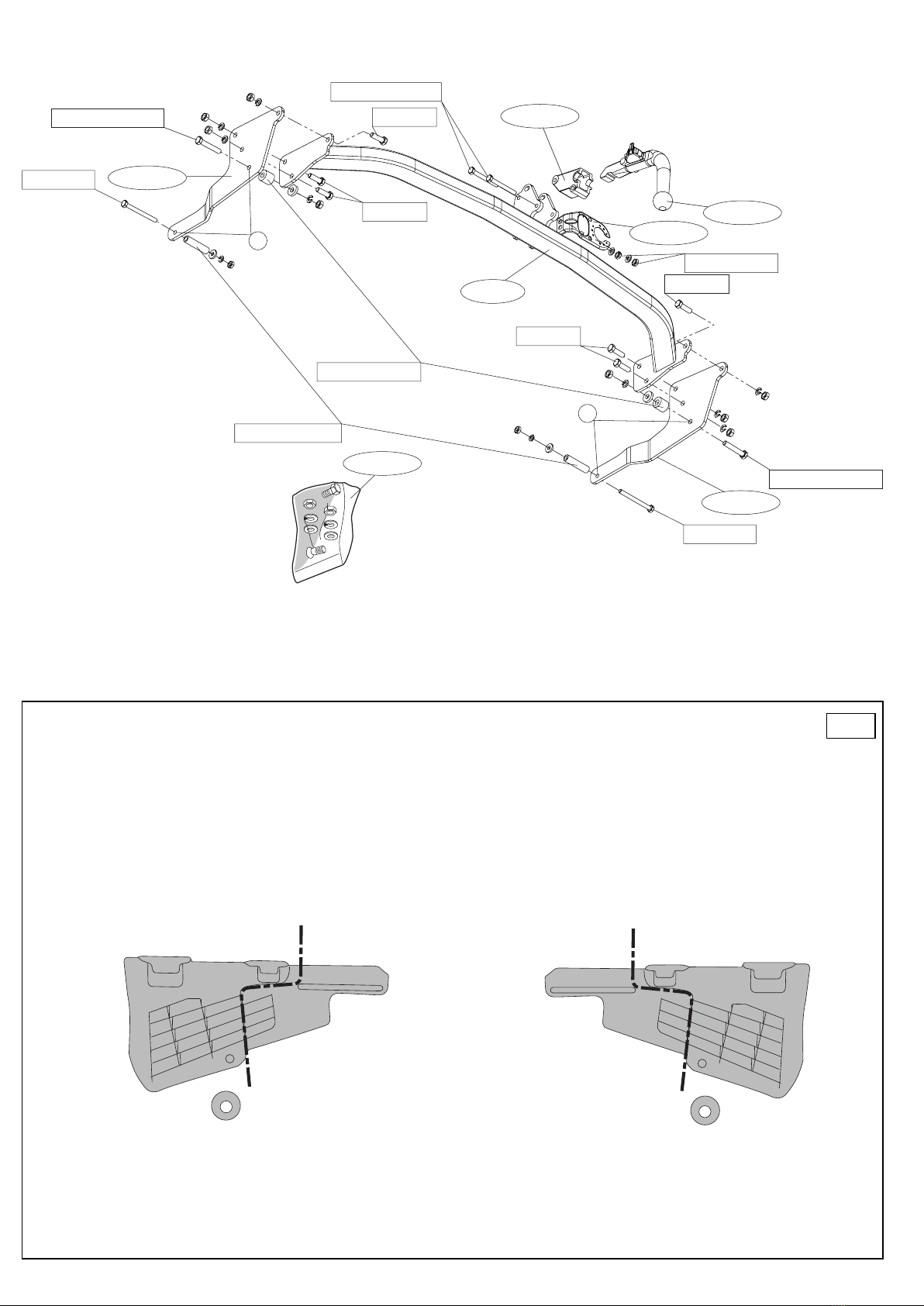
nego (Patrz rysunek 1).
5. Wypiłować zgodnie z rysunkiem 1 wskazane odcinki.
6. Umieścić płytę boczną (L) / (P) w punktach A.
7. Zamontować całość zupełnie lekko.
8. Zamontować odcinek poprzecznicy pomiędzy płytami bocznymi.
9. Zamontować obudowę kuli i płytę z gniazdem wtykowym.
10.Zamontować to co zostało usunięte.
11.Dokręcić wszystkie śruby i nakrętki zgodnie z tabelą.
Co do montażu i środków montażowych zapoznać się ze schema-
tem.
Co do montażu i demontażu zdejmowanej kuli zapoznać się z załąc-
zoną instrukcją montażu .
©327570/05-02-2004/7
PL
Wskazówki:
-Po przejechaniu 1000 km dokręcić wszystkie elementy skręcane.
-Podczas ewentualnych odwiertów upewnić się czy w pobliżu nie znaj-
dują się przewody instalacji elektrycznej, przewody hydrauliczne lub
przewody paliwowe.
-Wszystkie ubytki powłoki lakierniczej zabezpieczyć przed korozją.
-Należy wyjąć ewentualne plastikowe zaślepki w punktach przyspawa-
nych nakrętek.
-Stosować nakrętki oraz śruby gatunkowe dostarczone w komplecie.
-Utrzymywać kulę w czystości, oraz pamiętać o regularnym jej smaro-
waniu.
-Hak holowniczy zarejestrować w stacji diagnostycznej.
Zastosowanie się do powyższych wskazań gwarantuje Państwu bezpiec-
zeństwo, niezawodność i sprawność naszego wyrobu przez cały okres
jego użytkowania.
Montageanleitung:
1. Das Ersatzrad abmontieren
2. Auf der Unterseite der Stoßstange in der Mitte einen 100 mm breiten
und 30 mm tiefen Teil herausschneiden.
3. Die Hinterräder abmontieren.
4. Die Kunststoffschutzkappen abmontieren (Siehe Abbildung 1).
5. Gemäß Abb. 1 die angegebenen Teile heraussägen.
6. Die Seitenwand (L) / (R) bei den Punkten A anlegen.
7. Das Ganze halbfest anbringen.
8. Den Trägerteil zwischen die Seitenwände montieren.
9. Das Kugelgehäuse und die Steckdosenplatte montieren.
10.Das Entfernte montieren.
11.Alle Schrauben und Muttern gemäß den Angaben in der Tabelle festd-
rehen.
Für die Montage und die Befestigungsmittel die Skizze zu Rate zie-
hen.
Für die Montage und Demontage des abnehmbaren Kugelsystems
die beiliegende Montageanleitung zu Rate ziehen.
Instructions de montage:
1. Déposer la roue de secours.
2. Scier au milieu de la face inférieure du pare-chocs un morceau de 100
mm de large et 30 mm de profondeur.
3. Démonter les roues arrière.
4. Démonter les caches de protection en plastique (Voir la figure 1).
5. Scier les parties indiquées conformément à la figure 1.
6. Placer la plaque latérale (G) / (D) à l’emplacement des points A.
7. Serrer l’ensemble à la main..
8. Monter la poutre entre les plaques latérales.
9. Monter le logement de la rotule et la prise électrique..
10.Monter ce qui a été retiré.
11.Serrer tous les boulons et écrous conformément au tableau.
Consulter le croquis pour voir le montage et les moyens de fixation.
Pour le montage et le démontage de la rotule amovible, consulter la
notice de montage jointe.
©327570/05-02-2004/4
D*Die Quetschmuttern müssen nach einem späteren lösen der Muttern
gegen neue ausgetauscht werden, da ansonsten die Sicherungswirkung
nicht mehr garantiert ist!
HINWEISE:
*Für (eine) eventuell erforderliche Anpassung(en) "des Fahrzeugs" ist
der Händler zu Rate zu ziehen.
*Im Bereich der Anlageflächen muß Unterbodenschutz, Hohlraumkonser-
vierung (Wachs) und Antidröhnmaterial entfernt werden.
*Vor dem Bohren prüfen, daß keine, dort eventuell vorhandene Leitungen
beschädigt werden können.
*Alle Bohrspäne entfernen und gebohrte Löcher gegen Korrosion schüt-
zen.
*Entfernen Sie "falls vorhanden", die Plastikkappen von den Punkt-
schweißmuttern.
*Für das höchstzulässige Zuggewicht und der erlaubte Kugeldruck Ihres
Fahrzeugs ist IhrHändler zu befragen.
F
REMARQUE:
*Pour une/des adaptations indispensables sur le véhicule, veuillez con-
sulter le concessionnaire.
*Enlever la couche de bitume ou d'anti-tremblement qui recouvre éven-
tuellement les points de fixation.
*Pour connaître le poids de traction maximum et le poids en flèche sur la
rotule autorisée du véhicule, veuillez consulter votre concessionnaire.
*Veiller en perçant à ne pas endommager les conduites de électrique, de
frein et de carburant.
*Retirer "si présents" les embouts en plastique des écrous de soudure
par point.

Other Brink Automobile Accessories manuals

Brink 4517 User manual

Brink

Brink 4517 User manual

Brink 719054 User manual

Brink

Brink 719054 User manual

Brink 6808 User manual

Brink

Brink 6808 User manual

Brink 5041 User manual

Brink

Brink 5041 User manual

Brink 5679 User manual

Brink

Brink 5679 User manual

Brink 5430 User manual

Brink

Brink 5430 User manual

Brink 6012 User manual

Brink

Brink 6012 User manual

Brink 727533 User manual

Brink

Brink 727533 User manual

Brink 742828 29180527 User manual

Brink

Brink 742828 29180527 User manual

Brink 6020 User manual

Brink

Brink 6020 User manual

Brink 4487 User manual

Brink

Brink 4487 User manual

Brink 3615 User manual

Brink

Brink 3615 User manual

Brink 4281 User manual

Brink

Brink 4281 User manual

Brink 6194 User manual

Brink

Brink 6194 User manual

Brink 6678 User manual

Brink

Brink 6678 User manual

Brink 727644 User manual

Brink

Brink 727644 User manual

Brink 709553 User manual

Brink

Brink 709553 User manual

Brink 5051 User manual

Brink

Brink 5051 User manual

Brink 756843 User manual

Brink

Brink 756843 User manual

Brink 4405 User manual

Brink

Brink 4405 User manual

Brink 727639 User manual

Brink

Brink 727639 User manual

Brink 5485 User manual

Brink

Brink 5485 User manual

Brink 4399 User manual

Brink

Brink 4399 User manual

Brink 719063 User manual

Brink

Brink 719063 User manual

Popular Automobile Accessories manuals by other brands

Magneti Marelli AC161 Installation instruction

Magneti Marelli

Magneti Marelli AC161 Installation instruction

FDI uEZ GUI Start here

FDI

FDI uEZ GUI Start here

JCROffroad JT Install instructions

JCROffroad

JCROffroad JT Install instructions

Rostra VOXXElectronics 250-1930 owner's guide

Rostra

Rostra VOXXElectronics 250-1930 owner's guide

TOP VEHICLE TECH GR3FORD5 installation manual

TOP VEHICLE TECH

TOP VEHICLE TECH GR3FORD5 installation manual

Safe Fleet PRIME DESIGN AR-2000-BLK manual

Safe Fleet

Safe Fleet PRIME DESIGN AR-2000-BLK manual

Skoda Fabia Combi 5J Fitting instructions

Skoda

Skoda Fabia Combi 5J Fitting instructions

Camcar 40077 Al Mounting instructions

Camcar

Camcar 40077 Al Mounting instructions

Camcar 40089 AL Mounting instructions

Camcar

Camcar 40089 AL Mounting instructions

Impac Tradesman 2000 installation manual

Impac

Impac Tradesman 2000 installation manual

DVB OFFROAD BRSB-01 installation manual

DVB

DVB OFFROAD BRSB-01 installation manual

Safari Snorkel SS385HF installation guide

Safari Snorkel

Safari Snorkel SS385HF installation guide

ULTIMATE SPEED 279746 Assembly and Safety Advice

ULTIMATE SPEED

ULTIMATE SPEED 279746 Assembly and Safety Advice

SSV Works DF-F65 manual

SSV Works

SSV Works DF-F65 manual

ULTIMATE SPEED CARBON Assembly and Safety Advice

ULTIMATE SPEED

ULTIMATE SPEED CARBON Assembly and Safety Advice

Witter F174 Fitting instructions

Witter

Witter F174 Fitting instructions

WeatherTech No-Drill installation instructions

WeatherTech

WeatherTech No-Drill installation instructions

TAUBENREUTHER 1-336050 Installation instruction

TAUBENREUTHER

TAUBENREUTHER 1-336050 Installation instruction

manuals.online logo
manuals.online logoBrands
  • About & Mission
  • Contact us
  • Privacy Policy
  • Terms and Conditions

Copyright 2025 Manuals.Online. All Rights Reserved.