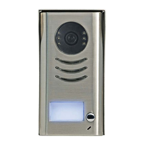
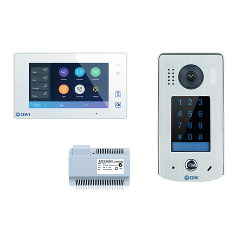
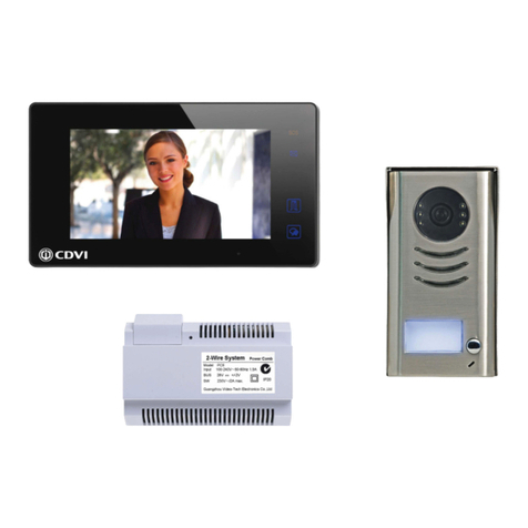
CDVI CDV-4791S-DXB User manual

2EASY 2-wire, 1-way Kit Manual, Black or
White Monitor
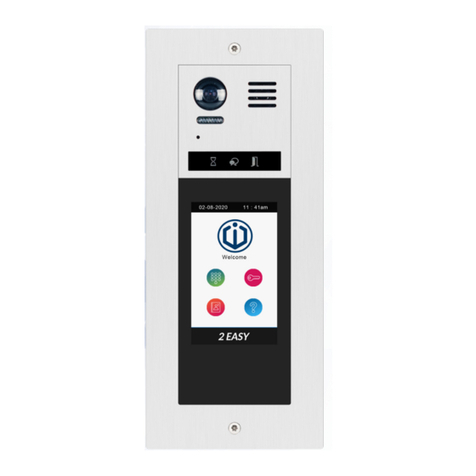
CDV-4791S-DXB,
CDV-4791S-DXW
EN
WARRANTY
YEAR
2

EN EN
2
CDV-4791S-DXB, CDV-4791S-DXW
2EASY 2-wire, 1-way Kit Manual, Black or White Monitor
1] CONTENTS
2] PACKAGE CONTENTS 3
3] CDV-91S DOOR STATION - PARTS AND FUNCTIONS 3
Terminal Description 3
Installation 4
4] CDV-PC7 POWER COMBINER - PARTS AND FUNCTIONS 4
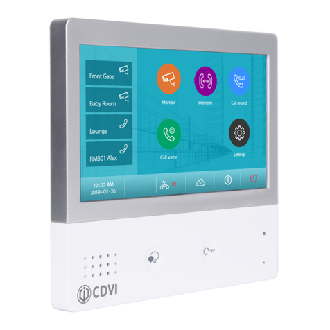
5] CDV-47DX MONITOR - PARTS AND FUNCTIONS 5
Terminal Description 5
Installation 6
Installer Settings 6-8
6] SYSTEM WIRING AND CONNECTIONS 9
Single Door Station System Wiring 9
Multi Door Stations System Wiring 9
Multi Monitors System Wiring 10-11
Electric Lock Connections 12
Cable Requirements 13-14
7] PRODUCT SPECIFICATIONS 15
CDV-91S Door Station 15
CDV-47DX Monitor 15
CDV-PC7 Power, Bus Combiner 15
Title Page
IMPORTANT
• This manual is limited in information. This manual gives basic installation requirements
of the CDV-4791S-DS kit. For advanced features, see the device’s full manuals on
the CDVI UK website: www.cdvi.co.uk
• For WiFi setup of the kit, see the CDV-47DX manual.

EN EN
3
CDV-4791S-DXB, CDV-4791S-DXW
2EASY 2-wire, 1-way Kit Manual, Black or White Monitor
2] PACKAGE CONTENTS
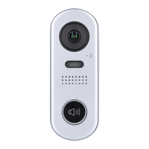
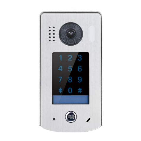
3] CDV-91S DOOR STATION - PARTS AND FUNCTIONS
Door
Station Internal
Monitor Power/ Bus
Combiner 145mm DIN
Rail Kit Manual
11111
Terminal Description
DIP:
• Bit 1&2: sets the door station address, a
total of 4 door stations can be supported.
Please refer to door station address
setting.
• Bit 3&4: sets the unlock time for door
station. Please refer to unlock time setting.
• Bit 5: sets the unlock mode for door
station (0(OFF):open/1(ON):closed).
• Bit 6: 0(OFF) --> 1(ON), to enter the
setting mode.
SD card
123 4 5 6
ON DIP

EN EN
4
CDV-4791S-DXB, CDV-4791S-DXW
2EASY 2-wire, 1-way Kit Manual, Black or White Monitor
Installation
1. The recommended installation height for the door station is 145-160cm.
2. Use screws to x the back panel to the wall and connect the cables correctly.
3. Attach the front panel to the back panel, then use the screw to secure the panel.
4] CDV-PC7 POWER COMBINER - PARTS AND FUNCTIONS
The CDV-PC7 is a power/bus combiner unit, which is designed for the CDV 2EASY 2-wire
system to supply power for the external station, internal monitor and other accessories
on the bus. It can operate as a normal power/bus combiner or auxiliary PSU.
Note: See next page for details of connection as an end-of-line PSU.
Terminal Description
L1, L2 Connect to the Bus line, no polarity
LK+ Lock power (+) output
LK- Lock power (-) ouput, connect to the power
(-) inputs of the lock
JP Lock Control Jumper

EN EN
5
CDV-4791S-DXB, CDV-4791S-DXW
2EASY 2-wire, 1-way Kit Manual, Black or White Monitor
The features are as follows:
• Universal AC input/full range
• Multi protection: short circuit, overload, over voltage
• Integrated with DPS (power separator)
• Support up to 4 to 8 monitors (dependent on models)
• DIN Rail Mounting
5] CDV-47DX MONITOR - PARTS AND FUNCTIONS
Terminal Description
USB-Wi-Fi adaptor
1 2 3 4 5 6
ON DIP
L2
L1
DIP Switches
SW+
SW-
RING
GND
NC
1 2 3 4 5 6
ON DIP
Terminal Description
L1, L2 Bus Line Terminal
SW+, SW- Doorbell input connection port
Ring, GND Extension buzzer input connection port
NC Reserved
DIP Switched
Bit1-Bit5
Bit6
Reserved
Video impedance matching switch
Set to ON if the monitor is at the end of
the line or operates with CDV-DBC4A1,
otherwise set to off
WARNING: TURN OFF THE MAINS INPUT BEFORE CONTINUING
1. Remove the
CDV-PC7 from the
DIN rail.
2. Unclick the base
of the DPS side.
3. Remove the base. 4. Lift off the top
and cut both ends of
the resistor shown,
remove the resistor.
5. Replace the top
and base in reverse.
NOTE: If the CDV-PC7 is used as an end-of-line PSU, follow the steps below.
HDR-60-24DPS(V2)HDR-30-24 DPS(V2)
PC7 PC7H

EN EN
6
CDV-4791S-DXB, CDV-4791S-DXW
2EASY 2-wire, 1-way Kit Manual, Black or White Monitor
Installation
145~160 cm
Mounting screw
x 2(included)
The unit
Mounting box
(size:86x86mm)
Mounting bracket
2 wire cable
The installation height is suggested as 145~160cm.
1. Use screws to fasten the mounting bracket to the wall with standard single gang
ush lightswitch box.
2. Connect the two wire cables to the unit.
3. Mount the unit to the mounting bracket, making sure the unit is securely attached
to the mounting bracket.
Main Menu
The Main Menu is your starting point for using all the applications on your monitor.
Touch the Unlock button, or touch anywhere on the screen when in standby mode - the
Main Menu will appear as follows:
Light
Touch to trigger an
optional RLC unit
to operate the light
function.
Wi-Fi status
Touch to enter
Wireless setting
options.
SIP cong
Touch to enter SIP
cong interface.
Intercom
Touch to enter intercom
selections.
Monitor
Touch to view outdoor scene.
Call Record
Touch to see calling in/
calling out records or
missed calls.
Settings
Press to enter setup interface.
Close
Touch to turn off the screen
and put the monitor in
standby mode.
Call Scene
Touch to activate the Do
Not Disturb and Divert
Call functions.
Touch this icon to
immediately enable the
indicated function.
Current date and
time. Touch to
enter the date
time set interface.
Status bar

EN EN
7
CDV-4791S-DXB, CDV-4791S-DXW
2EASY 2-wire, 1-way Kit Manual, Black or White Monitor
NB Item Description
Missed call
Displays when there is a missed call.
Touch to review the missed call in shortcut.
Do not disturb
Displays when the function is activated.
Touch to enter Call Scene interface in
shortcut.
Call transfer
SIP server connection active and congured
Touch to enter SIP server information
interface in shortcut.
SIP server connection disabled
SIP server connection active and not connected
WiFi connection active and not connected
Touch to enter the Wi-Fi settings interface
in shortcut.
WiFi connection disabled
WiFi connection active and congured
Installer Settings
Entering the Interface
The Installer Settings page contain the device address setting and system settings.
1. Touch to enter the Settings interface.
Current addtess [01]
Intercom enable Enable
IPC Setting
Monitor list manage
System settings
Installer
Call Tune
General
Installer
Wireless
About
2. Touch to enter the installer settings
interface.
User Code Settings
Touch to set the user code for each monitor.
1. Enter the code by typing in the number.
Current addtess [01]
Intercom enable Enable
IPC Setting
Monitor list manage
System settings
Installer
Call Tune
General
Installer
Wireless
About
Current Address
26

EN EN
8
CDV-4791S-DXB, CDV-4791S-DXW
2EASY 2-wire, 1-way Kit Manual, Black or White Monitor
2. Touch "OK" to save the code setting, complete and exit.
Note:
If dip switches 1-5 are set the monitor will show the "Dip switch setting" page.
A total of 32 numbers can be set, from 0-31.
Unlock Time Setting
Setting the unlock time.
You can change the unlock
time at any time. It can be set
from 1 to 99 seconds.
Current addtess [01]
Intercom enable Enable
IPC Setting
Monitor list manage
System settings
FW upgrade
Unlock time [03]
Unlock mode [Open]
Auto reboot [Enable]
Reboot
Installer Installer
Call Tune
General
Installer
Wireless
About
Call Tune
General
Installer
Wireless
About
Unlock time
08
Unlock Mode Setting
Setting the unlock mode.
There are two unlock modes:
1. Power-on-to-unlock type = Open
2. Power-off-to-unlock type = Close
Open
Close
Installer
Unlock mode
Current addtess [01]
Intercom enable Enable
IPC Setting
Monitor list manage
System settings
FW upgrade
Unlock time [03]
Unlock mode [Open]
Auto reboot [Enable]
Reboot
Installer Installer
Call Tune
General
Installer
Wireless
About
Call Tune
General
Installer
Wireless
About

EN EN
9
CDV-4791S-DXB, CDV-4791S-DXW
2EASY 2-wire, 1-way Kit Manual, Black or White Monitor
6] SYSTEM WIRING AND CONNECTIONS
Single Door Station System Wiring
100-240VAC
PC7
Multi Door Stations System Wiring (4 max*)
100-240VAC
PC7

EN EN
10
CDV-4791S-DXB, CDV-4791S-DXW
2EASY 2-wire, 1-way Kit Manual, Black or White Monitor
Multi Monitors System Wiring (4 max*)
Standard IN-OUT wiring
• The door station is compatible
with the 2EASY CDV-47 & CDV-
47DX monitors from CDVI.
• For the last monitor connected
to the system, DIP6 should be
set to ON.
100-240VAC
PC7
*IMPORTANT: Subject to cable type. Please see cable distance chart on pages
10-11. For further help, call CDVI Technical Support on +44 (0) 1628 531300 or visit
the CDVI Support Centre.

EN EN
11
CDV-4791S-DXB, CDV-4791S-DXW
2EASY 2-wire, 1-way Kit Manual, Black or White Monitor
Star topology wiring with CDV-DBC4A1
The system can be extended by up to 3 slave monitors for each monitor. We recommend
you use the CDVI distributor CDV-DBC4A for the extension.
100-240VAC
PC7

EN EN
12
CDV-4791S-DXB, CDV-4791S-DXW
2EASY 2-wire, 1-way Kit Manual, Black or White Monitor
Electric Lock Connections
Door lock controlled with internal power
Notes:
1. This mode only supports Fail Secure (power
on to unlock) Strikes.
2. The door lock is limited to 12V, and holding
current must be less than 250mA.
3. The door lock control is not timed from Exit
Button (EB).
4. The monitor’s Unlock Mode parameter
must be set to 0 (by default).
Door lock controlled with dry contact
Notes:
1. An external power supply must be used
according to the lock power requirements.
2. The internal relay contact is restricted to AC
or DC Max 24V/1A
3. Remove jumper before connecting.
4. Setup the monitor’s Unlock Mode for
different lock types.
• Power-on-to-unlock (fail secure): Unlock
Mode = 0 (default)
• Power-off-to-unlock (fail safe): Unlock Mode
= 1

EN EN
13
CDV-4791S-DXB, CDV-4791S-DXW
2EASY 2-wire, 1-way Kit Manual, Black or White Monitor
Cable Requirements
The maximum distance of the wiring is limited in the 2EASY system. Using different
cables may also affect the maximum distance which the system can reach.
Standard IN-OUT wiring
Cable and distance (unit: m)
Cable Usage A B
<2 IM B
<16
IM
Belden 9470 UTP
2x0.75mm2
60 100 40
Belden 8471 UTP
2x1mm2
80 120 60
A
B
Recommended cable:
16AWG, Belden 8471
PC7

EN EN
14
CDV-4791S-DXB, CDV-4791S-DXW
2EASY 2-wire, 1-way Kit Manual, Black or White Monitor
Star topology wiring with CDV-DBC4A1
Cable Usage A B C
Belden 9470 UTP
2x0.75mm2
60 60 30
Belden 8471 UTP
2x1mm2
80 80 40
Cable and distance (unit: m)
Recommended cable:
16AWG, Belden 8471
PC7

EN EN
15
CDV-4791S-DXB, CDV-4791S-DXW
2EASY 2-wire, 1-way Kit Manual, Black or White Monitor
7] PRODUCT SPECIFICATIONS
CDV-91S Door Station
Feature Description
Power Supply DC 20~28V
Power Consumption Standby 0.3W; Working 7W
Monitor Screen 7 Inch digital color TFT
Display Resolutions 800*3(R, G, B) x 480 pixels
Video Signal 1Vp-p, 75Ω, CCIR standard
Wiring 2 wires, non-polarity
Dimensions 132(H) × 226(W) × 18(D) mm
CDV-47DX Door Station
Feature Description
Power Supply 24 Vdc
Power Consumption Standby: 14mA, Working: 122mA
Camera Color CMOS, 2.0 megapixel
1/2.7’’ sheye camera, 170° wide angle
Lock Power Supply 12 Vdc, 250mA (internal Power)
Operating Temperature -15°C - +55°C
Dimensions 160(H) x 60(W) x 31.5(D) mm
IP Rating IP44
Feature Description
Input Voltage 100-240Vac
Input Frequency 50-60Hz
Rated Output Voltage 28Vdc
Rated Output Current 1.5A
Operating Temperature -100C~500C
SW Port Input Voltage Max 230Vac, 1.5A
Dimensions 70(H) x 98(W) x 59(D) mm
CDV-PC7 Power/ Bus Combiner

www.cdvigroup.com
CDVI Group
FRANCE (Headquarters)
Phone: +33 (0) 1 48 91 01 02
CDVI FRANCE + EXPORT
+33 (0) 1 48 91 01 02
www.cdvi.com
CDVI AMERICAS [CANADA - USA]
+1 (450) 682 7945
www.cdvi.ca
CDVI BENELUX [BELGIUM - NETHERLANDS - LUXEMBOURG]
+32 (0) 56 73 93 00
www.cdvibenelux.com
CDVI GERMANY
+49 (0) 175 2932 901
www.cdvi.de
CDVI TAIWAN
+886 (0) 42471 2188
www.cdvichina.cn
CDVI SUISSE
+41 (0) 21 882 18 41
www.cdvi.ch
CDVI CHINA
+86 (0) 10 84606132/82
www.cdvichina.cn
CDVI IBÉRICA [SPAIN - PORTUGAL]
+34 (0) 935 390 966
www.cdviberica.com
CDVI ITALIA
+39 (0) 321 90 573
www.cdvi.it
CDVI MAROC
+212 (0) 5 22 48 09 40
www.cdvi.ma
CDVI SWEDEN
[SWEDEN - DENMARK - NORWAY - FINLAND]
+46 (0) 31 760 19 30
www.cdvi.se
CDVI UK [UNITED KINGDOM - IRELAND]
+44 (0) 1628 531300
www.cdvi.co.uk
CDVI POLSKA
+48 (0) 12 659 23 44
www.cdvi.com.pl
All the information contained within this document (pictures, drawings, features, specications and dimensions)
could be perceptibly different and can be changed without prior notice. - Oct 2021
*CDV-4791S-DX_V02*
Reference : CDV-4791S-DX_V02
Extranet : CDVI_CDV-4791S-DX_IM_02_EN_A4_C
This manual suits for next models
1
Table of contents
Other CDVI Intercom System manuals

CDVI
CDVI 2EASY CDV-T5 User manual

CDVI
CDVI CDV4791S-DX User manual

CDVI
CDVI CDV-DDP User manual

CDVI
CDVI DMR18S User manual

CDVI
CDVI 2EASY CDV-96KP User manual

CDVI
CDVI KCIEN User manual

CDVI
CDVI 2EASY CDV-850IP User manual

CDVI
CDVI CDV-91IP User manual
CDVI
CDVI CD97-4ID User manual

CDVI
CDVI CDV91S User manual

CDVI
CDVI CDV4791 User manual

CDVI
CDVI CDV-DDP-F User manual

CDVI
CDVI 2EASY CDV-91S User manual

CDVI
CDVI CDV97-1ID User manual

CDVI
CDVI CDV-471IP User manual
CDVI
CDVI CDV-91 User manual
CDVI
CDVI CDV91F User manual

CDVI
CDVI CDV-91 User manual

CDVI
CDVI CDV4796KP-DX User manual
CDVI
CDVI 2EASY CDV-47DX User manual