QUICK START
INSTALLATION GUIDE
www.cdvi.ca
28,5 mm
1.1 in.
28,5 mm
1.1 in.
136 mm
5.4 in.
17 mm
0.7 in.0.7 in.
55 mm
2.2 in.
17 mm
44,5 mm
1.8 in.
READER PORT #1READER PORT #2
A22K CONTROLLER
Here are the LED status when connected to an
A22K ATRIUM controller :
Note:
Door output timings such as; unlock time (access granted),
door open too long pre-alarm and door open too long
alarm,canbemodiedintheATRIUMsoftware“Door
Properties” window.
LED State Buzzer Description
Steady blue - Standby (door se-
cure)
LED green 5 sec. Chirp beep Access granted
5 rapid red blinks
Steady
beep for
3 sec.
Access denied
Flashing blue -
Reader compromised
(lost its encryption
key)
Blinks green every
3 sec. - Door unlock schedule
Flashing red Steady
beep Door forced alarm
Flashing red Beep every
2 sec.
Door open too long
pre-alarm
Flashing red rapidly Fast beep Door open too long
alarm
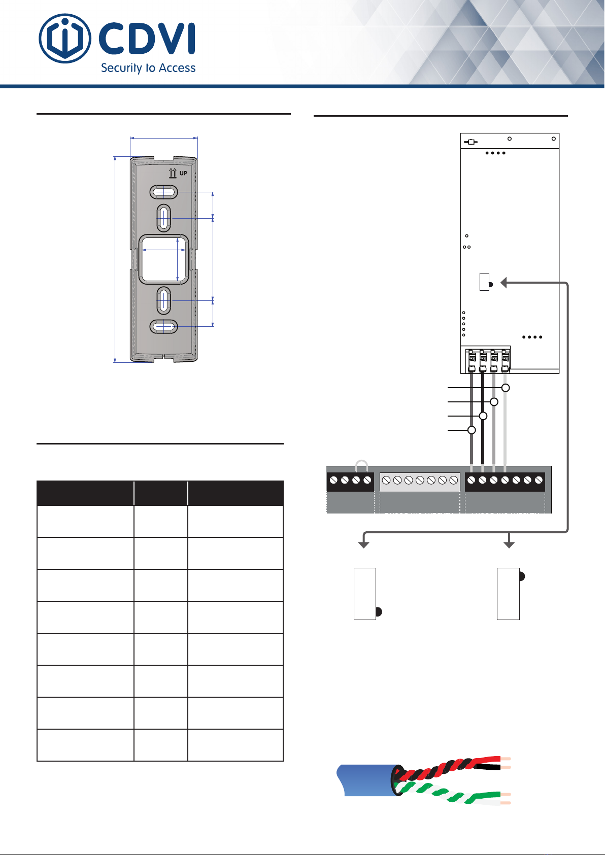
It is recommended to use twisted pair wiring as shown below
between the reader and the A22K ATRIUM controller.
Distance between the reader and the controller up to 1220m
(AWG 22 cable).
WIRING DIAGRAM
LED STATUS INDICATORS
MOUNTING
Alltheinformationcontainedwithinthisdocument(pictures,drawing,features,specicationsanddimensions)couldbe
perceptiblydierentandcanbechangedwithoutpriornotice.CDVI_K4_QS_03_FR-EN_A4_CMYK
D1 / B- (RS485 BUS)
D0 / A+ (RS485 BUS)
GND
12V DC
D1 / B-
RED1
GRN 1
BUZ 1
D0 / A+
12V
D1 / B-
RED 2
GND
GND
GND
GRN 2
BUZ 2
D0 / A+
12V
+12V DC
+24V DC
-
+12V DC
-
+12V DC
A+
B-
C 1
NO 1
NC 1
LK 1+
LK 1
-
LK 2
-
C 2
NO 2
NC 2
LK 2+
C 1
REX 1
12V
C 2
REX 2
12V
TMP
Input 1
Input 2
Output 1
Output 2
INPUT
POWER
SUPPLY
RS485
LOCAL
BUS
ETHERNET
PORT
SYSTEM STATUS
EXTRA
INPUTS/
OUTPUTS
A22K CONTROLLER
READER PORT DOOR 1
A22K CONTROLLER
READER PORT DOOR 2
DOOR 1 DOOR 2
ETHERNET LOCAL BUS LOCK 1 & 2
JUMPER SETTING
STATUS
24V DC INPUT/
BATTERY/
MODULE TYPE
BATTERY
BACKUP
ENCLOSURE
TAMPER
SWITCH
INPUT
INPUTS
DOOR 1 DOOR 2
LOCKS
Position the switch to the left
next to the terminal block
(manufacturer setting)
Position the switch
to the right
ENTRANCE READER EXIT READER
READER 1
READER 2
RS485 OUTPUT READER:
Each A22K controller supports
Entry/Exit reader option, 2 readers
per reader port. Connect the 2
readers in parallel as shown in the
diagram.
Set the position of the switch
before powering the reader, or
unplug and plug the reader if
you change the dip switch to the
output mode.
Makesuretoosetreaders by a
distance of 6 in. (20 cm) to avoid
any interference.
D0 / A+
12V
D1 / B-
GND


