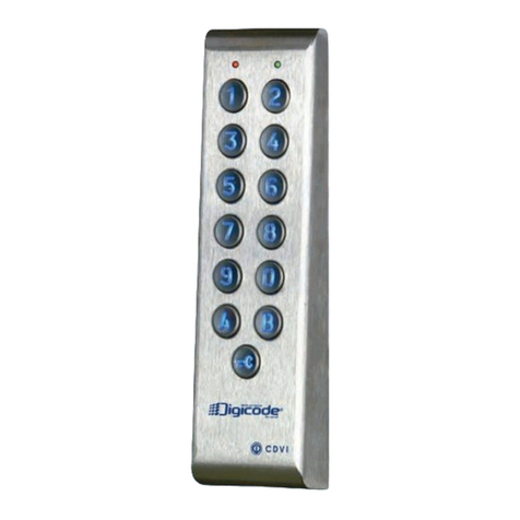
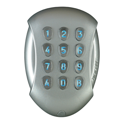
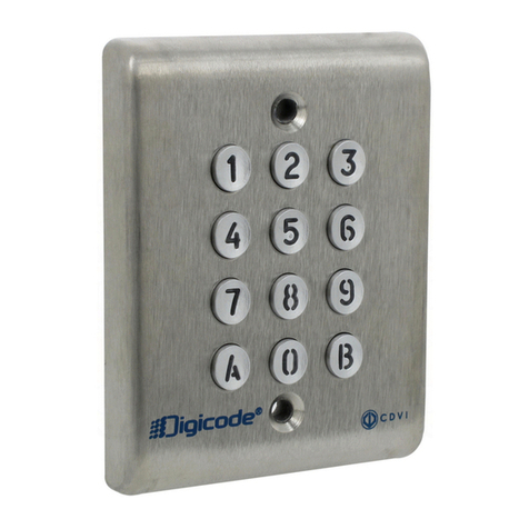
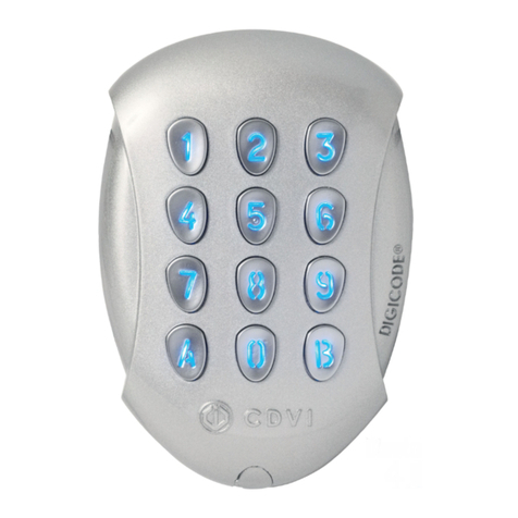
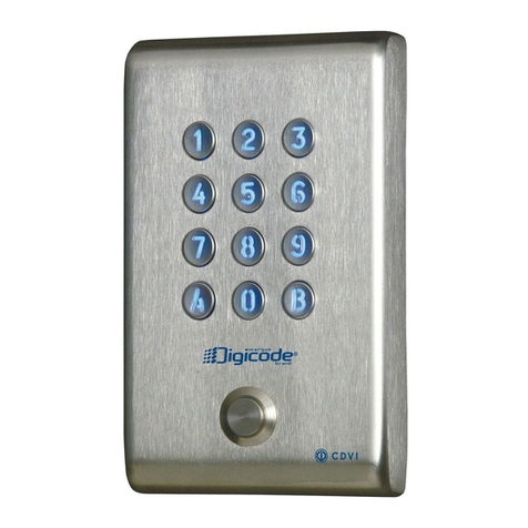
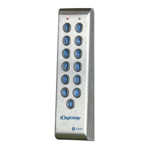
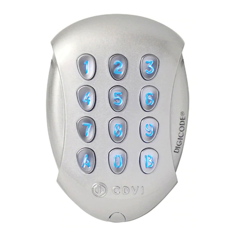
CDVI Galeo User manual

Version 01/2005 G0
301FR0234V01
1
I N S T A L L A T I O N
I N S T R U C T I O N S
GALEO
B
ACK
-
LIT
K
E S
K
E PAD
100
P
IN CODES AND
R
EMOTE
E
LECTRONICS
R
EMOTE
E
LECTRONIC
U
NIT
K
E PAD
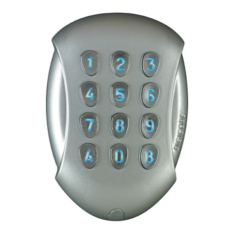
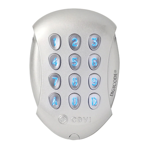
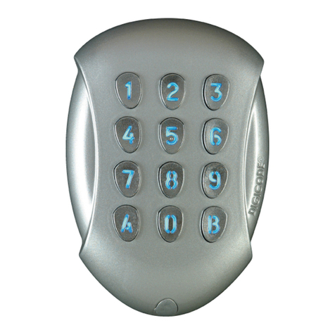
The GALEO keypad is available in 1, 2 or 3 relay output.
Refer to page 5 for for the instruction of version 2 and 3 relay of the GALEO.
Packing Checklist
:
GALEO keypad x 1
Remote Electronic unit x 1
Varistor x 1
Security screw x 1
Spanner
Caps x 2
Jumper x 1
Mounting screw x 4
Plastic anchor x 4
Wiring sealed cap x 2
Programming & Wiring
Instructions

Version 01/2005 G0
301FR0234V01
2
I. PRODUCT INFORMATION
A.
D
ESCRIPTION VERSION
1
RELAY OUTPUT
I
NPUT OLTAGE
12/36
AC
FREE OLTAGE
I
NPUT OLTAGE
12/48
DC
F
REE
OLTAGE
12-digit back-lit keys keypad
EPROM memory storage
100 Pin code programmables in 4 or 5-digit code
1 relay output N/O & N/C contact 8A/250V
1 programmable master code in 4 or 5-digit
Buzzer audible signal
1 request-to-exit input
P2 jumper: Reset master code and user codes
P3 jumper: modification of individual code by the user
B.
D
EFAULT
V
ALUES
Backlit Key time: 10 seconds keypad dimming
Relay release time: 1 second
Code length: 5-digit
Master Code: 12345
Programming mode time: 120 sec
Sub master code for user reprogram its Pin code (1 relay output version): A, B
C.
A
UDIBLE
S
IGNAL
1 short beep Keypad powered
1 long beep data computing in programming or access granted
2 short beeps Enter or Exit from programming
4 short beeps data computing error
D.
C
ODE
L
ENGTH
The master code and the User codes can be of 4 or 5-digit in length.
All the keypad keys can be used to program a code.
The master code and the Pin code can be of 4 or 5-digit code.
The master code CAN NOT be used as a PIN code (User Pin code).
Codes 00000 and 0000 can only be used to delete a user Pin code. To delete a specific User pin
Code replace it by 0000 if code length is 4-digit format or replace it by 00000 if the code is in 5-
digit format.
E.
R
EQUEST
-
TO
-E
XIT INPUT
This normally open loop that operates upon activation relay 1 (GALEO, GALEO 2 or GALEO 3) or relay
2 (GALEO 2 or 3 version). This feature is especially useful when controlling a lock.
P1 input activates relay 1.
P2 input activates relay 2.
(The output can be programmed).
The timer input H if connected allows using the 0 key as a request-to-enter. If the timer contact
is open then the 0 key is used for the Pin code and if the contact is closed then the 0 key is used
for the request-to-enter.
F.
C
ONSUMPTION
12VAC: 20mA in stand by, 80mA max all 3 relays activated
24V AC: 10mA in stand by, 50mA max all 3 relays activated
(Lock consumption not included)

Version 01/2005 G0
301FR0234V01
3
II. PROGRAMMING
A.
T
IME OUTPUTS
This section allows to program the backlighting time and the Relay activation time
1. Enter the master code twice (12345 default value master code).
2 beeps are emitted to confirm entry in programming mode.
2. Enter A0 to program the key-in keypad time and the keys lit time. 1 beep is emitted. Enter
the time in 10
th
of second – 10 for 10 seconds up to 99 for 99 seconds the backlighting dims 10
seconds after the last keypress or switches off after entering a valid code. Enter 00 for
permanent illumination keys. One beep is emitted to validate the time.
3. Enter A1 to program relay 1 output time (door release time). 1 beep is emitted. For a latched
output enter the time in seconds – 01 for 1 second up to 99 for 99 seconds. Enter 00 for a
toggled output. One beep is emitted to validate the time.
4. Press B to exit from programming mode. 2 beeps are emitted to confirm that the keypad is in
stand-by operating mode.
4 beeps indicate a data computing error.
B.
S
ETTING
C
ODE
L
ENGTH
1. Enter the master code twice (12345 default value master code). 2 beeps are emitted to confirm
entry in programming mode.
2. Enter A4 to program the code length. One beep is emitted. Enter 4 or 5 for the digit code. One
beep is emitted to confirm programming of the code length.
3. Enter A5 to modify the master code. One beep is emitted. Enter the new 4 or 5-digit master
code. One beep is emitted to confirm programming of the new master code.
4. Press B to exit from programming mode. 2 beeps are emitted to confirm that the keypad is in
stand-by operating mode.
C.
C
HANGING THE
M
ASTER CODE
The master code is used only to enter in programming mode
1. Enter the master code twice (12345 default value master code).
2 beeps are emitted to confirm entry in programming mode.
2. Enter A5 to modify the master code. One beep is emitted. Enter the new 4 or 5-digit master.
One beep is emitted to confirm that the master code is programmed.
3. Press B to exit from the programming mode. 2 beeps are emitted to confirm that the keypad is in
stand-by operating mode.
D.
R
ESET
M
ASTER
C
ODE AND
U
SER
C
ODES
1. Enter the master code twice (12345 default value master code).
2 beeps are emitted to confirm entry in programming mode.
2. Enter A6 to reset the Master Code and the User codes. One beep is emitted. Press on A
and
B to
confirm reset of all memory of the keypad. Wait for two beeps. The master code is restored to its
default value 12345 and all the User codes are deleted from the keypad.
Once the reset is completed then the keypad returns to a stand-by operating mode.
OR
1. Cut the power. Put the jumper on P2.
A0
A1
A4
A5
A6
P2

Version 01/2005 G0
301FR0234V01
4
2. Put the power back. Wait approximately 3 seconds. Two beeps are emitted to confirm reset of
the keypad. Remove P2 jumper. The master code is restored to its default value 12345 and all
the User codes are deleted from the keypad.
E.
R
ESET
M
ASTER
C
ODE
On stand-by operating mode, put a jumper on P2. Wait 1 second and then remove the jumper.
One beep is emitted. The master code is restored to its default value 12345 in 5-digit code and 1234
in 4-digit code.
F.
C
HANGING THE
S
UB MASTER CODE
The Sub Master code allows the user to change its own code without having to enter in
programming mode. For security reasons the code need to be changed periodically. This feature
makes it easier and faster to change its code.
1. Enter the master code twice (12345 default value master code).
2 beeps are emitted to confirm entry in programming mode.
2. Enter A7 to program a sub master code for the user individual Pin code modification. One
beep is emitted. Enter the new 2-digit sub master code. One beep is emitted to confirm
programming of the sub master code.
3. Press B to exit from the programming mode. 2 beeps are emitted to confirm that the keypad is in
stand-by operating mode.
G.
A
DDING
,
CHANGING OR DELETING A
U
SER
C
ODE
Group 1: from address 00 to address 99, relay output 1
1. Enter the master code twice (12345 default value master code).
2 beeps are emitted to confirm entry in programming mode.
2. To Add a user code enter the user location (from 00 to 99). If the user location is free 1 beep is
emitted, enter the 4 or 5-digit User code.
3. To Change a User code enter the user location, 4 beeps are emitted to indicate that user location
is already programmed. Enter a new 4 or 5-digit code. A beep is emitted to confirm the new user
code.
4. To delete a User code enter the user location, 4 beeps are emitted. Enter 00000 in 5-digit length
code or 0000 in 4-digit length code. A beep is emitted to confirm the new user code.
NOTE: If the Pin code is already programmed or is identical to the master code, then 4 beeps are
emitted.
Press B to exit from the programming mode. 2 beeps are emitted to confirm that the keypad is in
stand-by operating mode.
H.
C
HANGING THE
C
ODE BY A
U
SER
To authorize a user to modify its own User code put a jumper on P3 (to disable the feature remove the
jumper).
1. Enter the old user code. The relay is activated and a beep is emitted.
2. Enter the 2-digit sub master code (default sub master code A and B).
A beep is emitted to authorise the modification.
3. Enter the new user code. 2 beeps are emitted to confirm the new code.
4. Check the new user code to be sure of the modification.
A7
00
to
99
P3

Version 01/2005 G0
301FR0234V01
5
I.
A
DDING
U
SER CODES
To program Pin codes:
User Pin code list
00
01
02
03
04
05
06
07
08
09
10
11
12
13
14
15
16
17
18
19
20
21
22
23
24
25
26
27
28
29
30
31
32
33
34
35
36
37
38
39
40
41
42
43
44
45
46
47
48
49
50
51
52
53
54
55
56
57
58
59
60
61
62
63
64
65
66
67
68
69
70
71
72
73
74
75
76
77
78
79
80
81
82
83
84
85
86
87
88
89
90
91
92
93
94
95
96
97
98
99
To exit from the programming mode, press B. 2 audible beeps indicate that the keypad is in stand-by
mode.
J.
GALEO
2
AND
3
P
ROGRAMMING
I
NSTRUCTION
Programming instructions are the same as for the GALEO keypad with 1 relay output.
GALEO 2: 2 relay outputs N/O and N/C contacts 8A @ 250V~
Group 1: from user location 00 to user location 59 to activate relay 1
Group 2: from user location 60 to user location 99 to activate relay 2
Release Time of relay2 enter A2 sub master code enter A8 (default values 1 and 3).
GALEO 3: 3 relay outputs N/O and N/C contacts 8A @ 250V~
Group 1: from user location 00 to user location 59 to activate relay 1
Group 2: from user location 60 to user location 79 to activate relay 2
Group 3: from user location 80 to user location 99 to activate relay 3
Release time for relay 3 enter A3 sub master code enter A9 (default values 4 and 6).
Master code
Master code
2 audible
beeps
A2
A8
A3
A9

Version 01/2005 G0
301FR0234V01
6
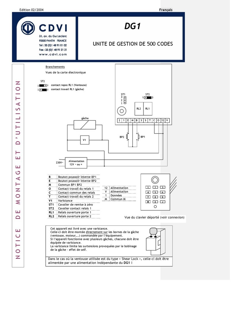
Wiring diagram between the GALEO and the Remote Controller
Terminals
Description
12 Input Voltage 12V or 24V AC/DC
V Input Voltage 12V or 24V AC/DC
R1 N/C contact relay 1
C1 Common relay 1
T1 N/O contact relay 1
R2 N/C contact relay 2
C2 Common relay 2
T2 N/O contact relay 2
R3 N/C contact relay 3
C3 Common relay 3
T3 N/O contact relay 3
P1 Request-to-exit input relay 1
M Common of inputs
P2 Request-to-exit input relay 2
H Timer Contact
+ White cable from keypad
- Brown cable from keypad
E Blue cable from keypad (backlit keys)
Strike
P1
P2 H
V
Strike
Input Voltage 12V
or 24V AC/DC
according to the lock
power specification
2
12 V R1 C1 T1 R2 C2 T2 R3 C3 T3 P1 M P2 Px H H +
-
E
Blue
Brown
White
V
V
RL1
RL2
RL3
Input Voltage
12-48VDC or 12-36 VAC
2
P3 P2
P2
: Place jumper for reset
P3: Individual Code
modification by user
ST1: Cut the wire to
disable the audible signal
Distance
10 meters
ST1
This device comes with a varistor.
The varistor must be connected on the strike
terminal (electromagnet…) operated by the device.
If this product operates more than one strikes, each
lock should have a varistor.
The varistor controls the overload produced by the
strike coil – back emf.
If you are using a «
Shear Lock
Magnet, it is
recommended to use a separate power supply
Other manuals for Galeo
4
Table of contents
Other CDVI Keypad manuals

CDVI
CDVI C2R User manual

CDVI
CDVI KCIEN User manual

CDVI
CDVI DGA User manual

CDVI
CDVI Digicode Series User manual

CDVI
CDVI GALEOR User manual

CDVI
CDVI KCIN User manual

CDVI
CDVI Galeo 2 User manual

CDVI
CDVI Digicode PROFIL100EC User manual

CDVI
CDVI GALEOR User manual

CDVI
CDVI GALEO 4.0 - Bluetooth User manual
Popular Keypad manuals by other brands

Local Control Network
Local Control Network LCN-GT10D installation guide

Honeywell
Honeywell Lyric LKP500-ENC Installation and setup guide

Niles
Niles Transport Specifications

Lenel
Lenel OnGuard 2013 installation guide

Ortek
Ortek WPM-900-01 user manual

Amano
Amano Time Guardian Series Installation and user guide