usar códigos de 4 dígitos, el código maestro y
los códigos de usuario se verán afectados de la
siguiente manera:
Paso de 5 a 4 dígitos:
Si el código maestro es 12369, pasará a ser
2369. Los códigos de acceso sufrirán el mismo
proceso.
Paso de 4 a 5 dígitos:
Si el código maestro es 2369, pasará a ser
02369. Los códigos de acceso sufrirán el mismo
proceso.
C. Programación del código
maestro
1. Introduzca 2 veces el código maestro.
- Por defecto, el código es: 12345.
- Se emiten dos pitidos para conrmar la
entrada en modo de programación.
2. Teclee A5.
- Se emitirá un pitido.
- Teclee los dígitos del nuevo código
maestro.
- Se emitirá un pitido para conrmar la
programación.
3. Pulse B para salir del modo de
programación.
Se emitirán dos pitidos para conrmar la
salida del modo de programación.
D. Programación de códigos de
usuario
Dependiendo del número de relés de su
KCIN, los grupos de usuario serán los
siguientes:
- KCIN 2 Relés
Grupo 1 (relé 1): De 00 a 59.
Grupo 2 (relé 2): De 60 a 99.
- KCIN 3 Relés
Grupo 1 (relé 1): De 00 a 59.
Grupo 2 (relé 2): De 60 a 79.
Grupo 3 (relé 3): De 80 a 99.
1. Introduzca 2 veces el código maestro.
- Por defecto, el código es: 12345.
- Se emiten dos pitidos para conrmar la
entrada en modo de programación.
2. Teclee la posición de memoria a
programar. (en función del número de
relés de su KCIN).
- Si la posición está libre, teclee los dígitos
del nuevo código de usuario. Si la
posición está ocupada, se emitirán 4
pitidos.
- Teclee los dígitos del nuevo código para
sobreescribirlo, o teclee 00000 o 0000
para borrar el código.
- Se emitirá un pitido para conrmar la
programación.
3. Pulse B para salir del modo de
programación.
Se emitirán dos pitidos para conrmar la
salida del modo de programación.
Si el código introducido ya existiera o se
correspondiera con el código maestro, se
emitirán 4 pitidos. Los códigos 00000 y
0000 sólo se usan para borrar un código
existente y no se pueden usar como
códigos de acceso.
E. Temporizaciones
1. Introduzca 2 veces el código maestro.
- Por defecto, el código es: 12345.
- Se emiten dos pitidos para conrmar la
entrada en modo de programación.
2. Teclee A0 para programar la
temporización del teclado.
- Se emitirá un pitido.
-
Teclee, en segundos, la duración de la
iluminación del teclado (por ejemplo, para
10 segundos, teclee «10»). Teclear «00»
indicará iluminación permanente.
- Se emitirá un pitido.
3. Relé 1 (Grupo 1): Teclee A1.
Relé 2 (Grupo 2): Teclee A2.
Relé 3 (Grupo 3): Teclee A3.
-
Estas opciones le permiten gestionar el
tiempo de activación de los relés de su
KCIN
.
- Se emitirá un pitido.
-
Teclee la duración en segundos del tiempo
de activación del relé (por ejemplo, para 1
segundo, teclee «01»). Teclear «00»
congurará el relé como biestable.
- Se emitirá un pitido.
4.
Pulse B para salir del modo de
programación.
Se emitirán dos pitidos para conrmar la
salida del modo de programación.
4 pitidos indican un error en
la introducción de datos.
55cdvigroup.com
ES
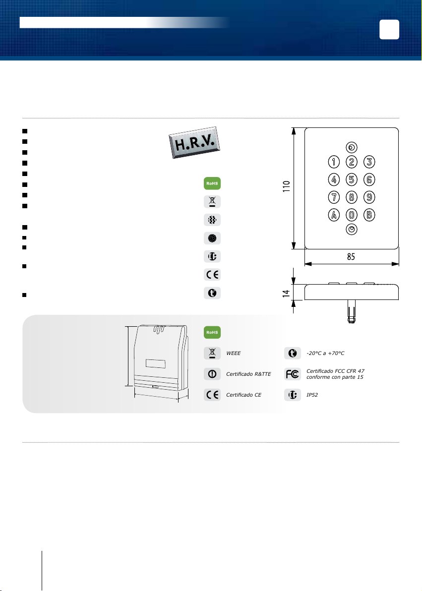
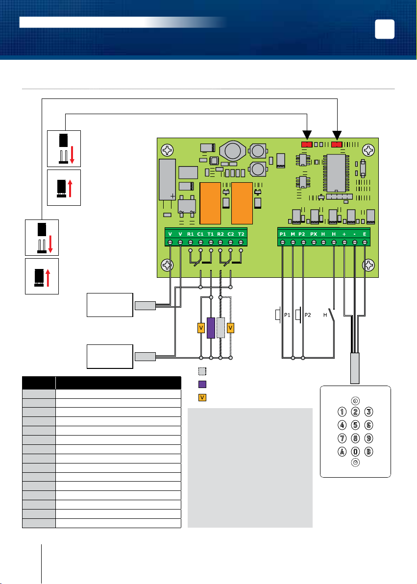
KCIN
Teclado retroiluminado con electrónica externa
MANUAL DE INSTALACIÓN