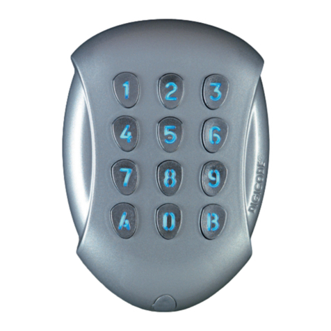
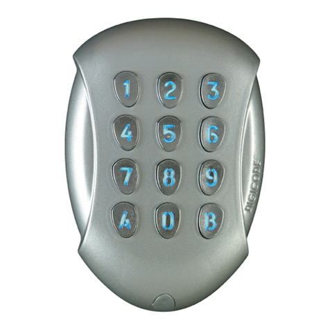
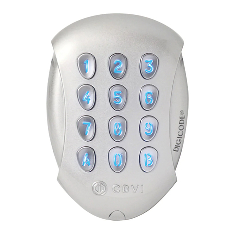
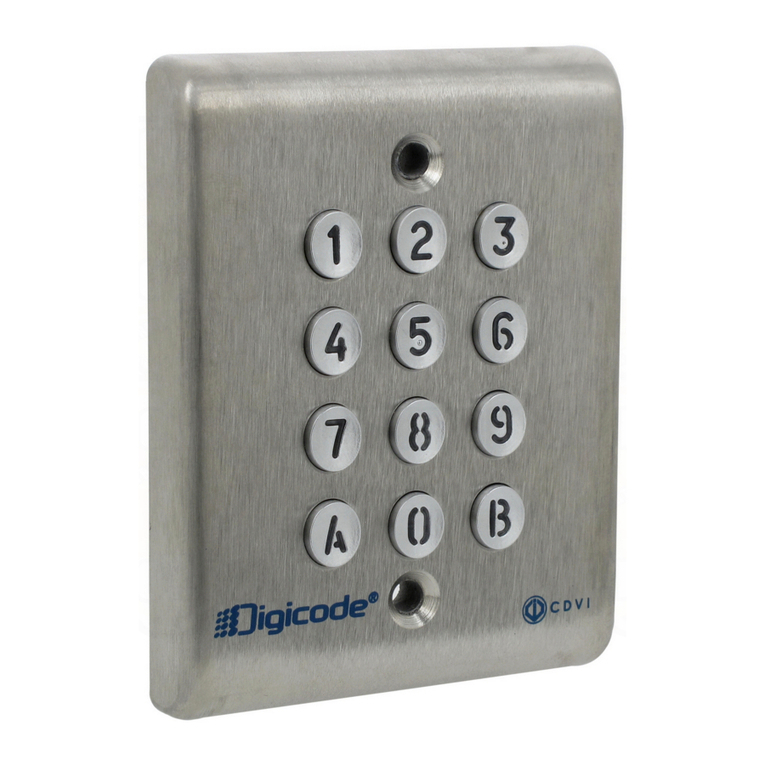
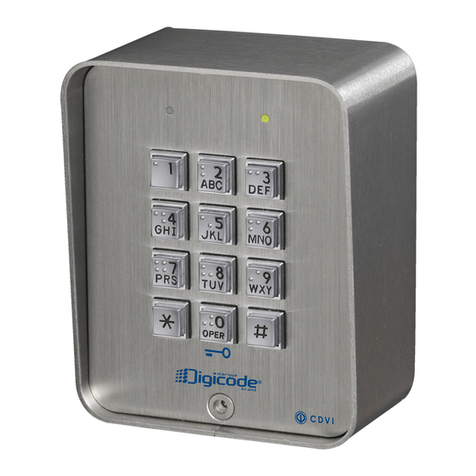
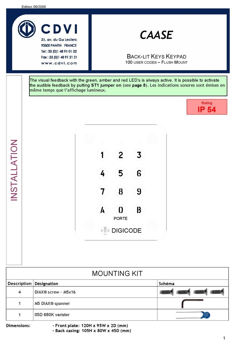
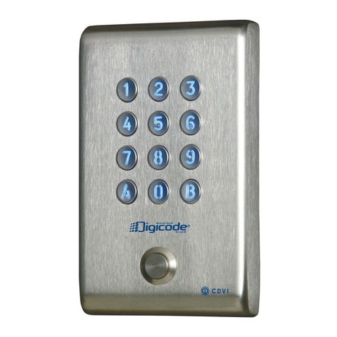
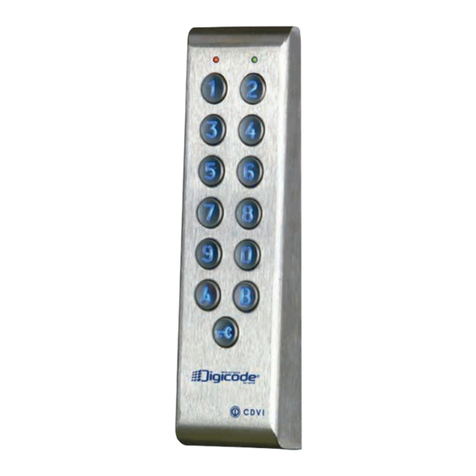
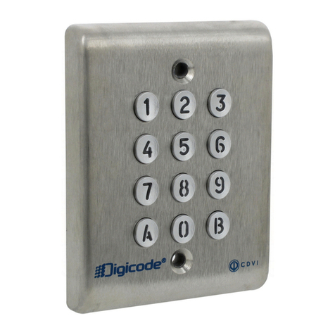
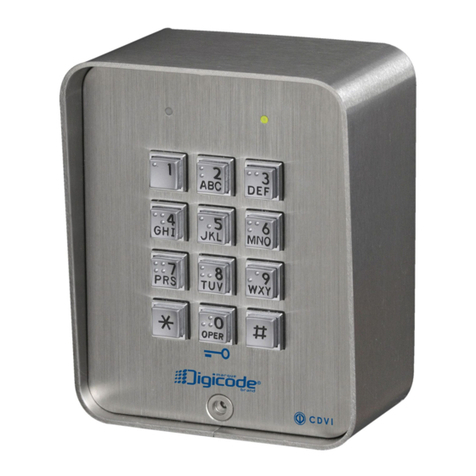
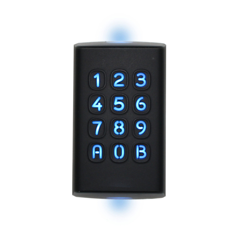
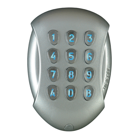
CDVI Digicode DGA User manual

CDVI Group Products cdvigroup.com
DGA
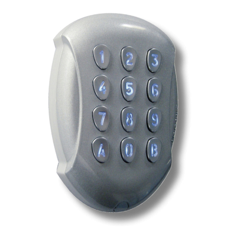
Illuminated Mullion Weatherproof Keypad Self Contained
Clavier codé rétro-éclairé avec électronique intégrée
Hintergrundbeleuchtete Kodetastatur mit integrierter Elektronik
Range: Digicode® INSTALLATION MANUAL
Gamme: Digicode® MANUEL D’INSTALLATION
Reihe: Digicode® INSTALLATIONSANLEITUNG
ENGLISH
EN
FRANCAIS
FR
DEUTSCH
DE

The installer’s choice
cdvigroup.com
ENGLISH
EN
FRANCAIS
FR
DGA
Self Contained Digicode®Keypad
Digicode®avec électronique intégrée

120
98 25
Illuminated keypad.
Cast aluminium body.
2 relay.
Surface mount.
Free voltage**
100 user codes.
Torx®mounting screws.
2 relay outputs, N/O and N/C contact 8A/250V.
100 user codes in 4 to 6 digits.
All programming stored in non-volatile
EEPROM memory.
1 request-to-Exit input.
1 master code.
Modication of Pin code by the user.
Visual and sound feedback.
Keypad Illumination :
Permanent or timed.
Operating voltage:
- 12V to 24VAC,
- 12V to 48VDC.
Consumption : 25 to 80 mA.
1] PRODUCT PREVIEW
The DGA a self contained keypad, under the Digicode®brand, was engineered
to secure your accesses. The DGA will compliment any audio or video entry systems
to control the operation and locking of your doors and gates. Its design and its high
resistance to vandalism make it suitable to secure residential as well as industrial
sites. Its compatibility with all CDVI locking devices gives you the exibility to set
your own personalized system while keeping a high security level.
IP64
Environmental tests
Salt spray
-25°C à +70°C
CE Certication
HIGH RESISTANCE
TO VANDALISM
WEEE & RoHS
2] PROGRAMMING
AUDIBLE SIGNAL
- 1 short beep > Keypad powered,
- 1 long beep > data computing in programming or access granted,
- 2 short beeps > Enter or Exit from programming,
- 4 short beeps > Data computing error.
CODE LENGTH
- All the keypad keys can be used to program a code,
- The master code and the Pin code can be of 4, 5 or 6-digits,
- The master code CAN NOT be used as a PIN code (User Pin code),
- Codes 000000, 00000 and 0000 can only be used to delete a user code,
- To delete a specic User Code replace it by 0000 if code length is 4-digit format or replace it
by 00000 if the code is in 5-digit format.
REQUEST-TO-EXIT INPUT
P1 input activates relay 1. (The output can be programmed) :
- The timer input H1 if connected allows using the 0 key as a request-to-enter,
- If the timer contact is open then the 0 digit key is used for the Pin code,
- if the contact is closed all keys are used for the request-to-enter.
CONSUMPTION
- 12V AC: in stand-by 20 mA, when 2 relay outputs activated 80 mA max,
- 24V AC: in stand-by 10 mA, when 2 relay outputs activated 40 mA max.
RESET MASTER CODE AND DELETE ALL USER CODES
1] Enter the master code twice (12345 default value master code):
- the red LED lights on to conrm entry in programming mode.
2] Press A6 to enter in the reset menu:
- the green LED lights on for 1 second,
- press simultaneously on A and B to start the reset,
- the green LED lights during all the reset process, wait until it lights off,
- the master code is reset to its factory value 12345 and all the user codes are deleted,
- the keypad is reset to the factory default values, the red LED lights on then lights off.
------------------------------------------------------ OR ---------------------------------------------------------
1] Turn off the power. Short the white and the yellow wires.
2] Power on the keypad:
- the green LED lights on,
- wait a few seconds, one beep is emitted. The green LED lights off. Unshort the wires.
3] The keypad is reset to the factory default values.
SETTING CODE LENGTH
1] Enter the master code twice (12345 default value master code) :
- the red LED lights on to conrm entry in programming mode
2] Press A4 to program the code length:
- the green LED lights on during 1 second,
- press 4, 5 or 6 to enter the code length,
DEFAULT FACTORY VALUES
- No code programmed in the keypad, - Programming mode time: 120 seconds,
- Illumination time: 10 seconds, - Sub master code for user to reprogram its Pin code group #1: A and B,
- Relay output time: 1 second, - Sub master code for user to reprogram its Pin code group #2: 1 and 3,
- Code length: 5-digits, - Red LED lights on when the keypad is powered.
- Master code: 12345,
23cdvigroup.com cdvigroup.com
ENEN DGA
Cast aluminium Digicode® Self Contained
DGA
Cast aluminium Digicode® Self Contained
INSTALLATION MANUALINSTALLATION MANUAL
Thank you for buying our products and for the condence you placed
in our company.

- the green LED lights on during 1 second to conrm programming of the code length.
3] Enter A5 to modify the master code:
- the green LED lights on during 1 second,
- enter the new 4 or 5 or 6-digit master code,
- the green LED lights on during 1 second to conrm programming of the new master code.
4] Press B to exit from programming mode:
- the red LED lights off to conrm exit from programming.
The red LED ashes 4 times to indicate a data computing error
Master code or user code: 12369
When changing to 4-digit code: enter 2369
When changing to 6-digit code: enter 012369
It is recommended to program the codes in 6-digits
and then modify the code length.
CHANGING THE MASTER CODE
1] Enter the master code twice (12345 default value master code):
- the red LED lights to conrm entry in programming mode.
2] Press A5:
- the green LED lights on during 1 second,
- enter the new master code (according to the code length set up),
- the green LED lights on during 1 second to conrm programming.
3] Press B to exit from programming mode. The red LED lights off to conrm exit from programming.
ADDING USER CODES
Group 1: from user number 00 to user number 59, relay 1
Group 2: from user number 60 to user number 99, relay 2
1] Enter the master code twice (12345 default master code):
- the red LED lights on to conrm entry in programming mode.
- pour programmer des codes :
MASTER CODE
MASTER CODE
RED LED
LIGHTS ON
2] To add a user code, enter the user number (from 00 to 99):
- If the user number is free, the green LED lights during 1 second enter the 4, 5 or 6-digit code,
- If the user number is already programmed, the red LED ashes 4 times,
- To modify the user code enter a 4, 5 or 6 digit code,
- To cancel the user code enter 000000 or 00000 or 0000 code,
- The green LED lights on duri ng 1 second to conrm programming.
If the user code is already programmed or is identical to the master code,
then the red LED
ashes 4 times to indicates a data computing error.
Note that the codes 000000 or 00000
or 0000 are strictly used to deleted a user code only.
3]
Press B to exit from programming mode. The red LED lights off to conrm exit from programming.
USER CODE LIST
00 25 50 75
01 26 51 76
02 27 52 77
03 28 53 78
04 29 54 79
05 30 55 80
06 31 56 81
07 32 57 82
08 33 58 83
09 34 59 84
10 35 60 85
11 36 61 86
12 37 62 87
13 38 63 88
14 39 64 89
15 40 65 90
16 41 66 91
17 42 67 92
18 43 68 93
19 44 69 94
20 45 70 95
21 46 71 96
22 47 72 97
23 48 73 98
24 49 74 99
SETTING ILLUMINATION AND OUTPUT TIME
1] Enter the master code twice (12345 default value master code):
- the red LED lights on to conrm entry in programming mode
2] Press A0 to program the key-in keypad time and the illumination time:
4 5cdvigroup.com cdvigroup.com
ENEN DGA
Cast aluminium Digicode® Self Contained
DGA
Cast aluminium Digicode® Self Contained
INSTALLATION MANUALINSTALLATION MANUAL

- the green LED lights during 1 second. Enter the time in 10th of second 10 for 10 seconds up to 99 for 99
seconds the backlighting dims 10 seconds after the last keypress or switches off after entering a valid code,
- enter 00 for a permanent illumination keys. The green LED lights during 1 second.
3] Press A1 to program relay 1 output time (door release time):
- the green LED lights during 1 second,
- for a timed output enter the time in seconds 01 for 1 second up to 99 for 99 seconds,
- enter 00 for a latched output,
- the green LED lights during 1 second to validate the time.
4] Press A2 to program relay 2 output time (door release time):
- the green LED lights during 1 second,
- for a timed output enter the time in seconds – 01 for 1 second up to 99 for 99 seconds,
- enter 00 for a latched output. The green LED lights during 1 second to validate the time.
5] Press B to exit from programming mode:
- the red LED lights to conrm exit from programming.
The red LED ashes 4 times to indicate a data computing error.
RESET MASTER CODE
Short the white and the yellow wires:
- the green LED lights on,
- one beep is emitted,
- wait until the green LED lights off. Separate the two wires,
- the master code is reset to the factory default value 123456 in 6-digit code length, 12345 in 5-digit
code length or 1234 in 4-digit code length.
CHANGING THE CODE BY THE USER
To authorize a user to modify its own User code short the blue and the yellow wires (Separate the two wires
to disable this function).
1] Enter the old user code:
- the relay is activated and the green LED lights on.
2] Enter the 2-digit sub master code (default sub master code A and B):
- the red LED lights on to authorize the modication.
3] Enter the new user code:
- the green LED lights during 1 second to conrm the new user code The red LED lights off.
4] Check the new user code to make sure of the modication.
SETTING A SUB MASTER CODE
The Sub Master code allows the user to change its own code without entering in programming mode. For
security reasons the code need to be changed periodically. This feature makes it easier and faster to change
its code
1] Enter the master code twice (12345 default master code):
- the red LED lights on to conrm entry in programming.
2] Press A7 to program a sub master code for the user individual Pin code modication of Group 1:
- the green LED lights on during 1 second,
- enter the new 2-digit sub master code,
- the green LED lights on during 1 second to conrm programming of the sub master.
3] Press A8 to program a sub master code for the user individual Pin code modication of Group 2:
- the green LED lights on during 1 second,
- enter the new 2-digit sub master code,
- the green LED lights on during 1 second to conrm programming of the sub master.
4] Press B to exit from programming:
- the red LED lights off to conrm exit from programming.
AUDIBLE SIGNAL
The audible signal is enabled in programming mode and when the relay is energised after a valid code.
To enable the audible feedback on a key press:
1] Enter the master code twice (12345 default value master code):
- 2 beeps are emitted to conrm entry in programming mode.
2] Press A twice:
- One beep is emitted,
- Press 0 to disable the audible signal during a keypress,
- Press 1 to enable the audible signal during a keypress,
- One beep conrms the modication.
3] Press B to exit from programming:
- 2 beeps are emitted to conrm exit from programming mode.
6 7cdvigroup.com cdvigroup.com
ENEN DGA
Cast aluminium Digicode® Self Contained
DGA
Cast aluminium Digicode® Self Contained
INSTALLATION MANUALINSTALLATION MANUAL

DGA 11122
1
(X2)
(X2)
2
Digicode
3
P1
H
V
V
V
05D 680K
Varistor
Spanner
for Torx®
T20 screws
M4x10
Torx®screw
M4x30
screws
S5 plastic
anchor
5] MOUNTING INSTRUCTION
Once you have made sure that the mounting kit is complete and that you prepared the cables
of the DGA keypad then you can proceed and mount the product. Make sure that you have
all the appropriate tools (drill, screw drivers and a meter tape...) and follow the mounting
instructions of the DGA keypad.
Take the marks with the back plate
of the DGA. Drill the 2 mounting
holes (Ø 5 MM bit and 35 MM depth
minimum) and the wiring access
hole.
Insert the 2 plastic anchors. Then
mount the back plate of the DGA
keypad, and screw on the wall with
the (M4x30) mounting screws.
Insert the cable of the keypad in
the wiring access area.
Place the keypad on the back plate
top rst and then make sure that it
ts all over the back plate.
fasten the screw at the buttom
of the DGA keypad with the Torx®
screw using the spanner.
4] MOUNTING KIT
3] WIRING DIAGRAM
This device comes with a
varistor. The varistor must
be connected on the strike
terminal (electromagnet…)
operated by the device. If
this product operates more
than one strike, each lock
should have a varistor. The
varistor controls the overload
produced by the strike coil –
back emf.
Wires Description
Black Input voltage 12V or 24V AC or DC
Red Input voltage 12V or 24V AC or DC
Brown Relay 1 N/C contact
Pink Relais 1 common
Orange Relay 1 N/O contact
Yellow Common
Dark Green Relay 1 request-to-exit input
Light Green H Timer input
Blue User code modication
Dark Blue Relay 2 N/C contact
Purple Relais 2 common
Gray Relay 2 N/O contact
White Reset
Varistor
INPUT VOLTAGE
12V à 24VAC
12V à 48VDC
INPUT VOLTAGE
Locking devices
230 V ELECTROMAGNET
Black
Red
Pink [C1]
Brown [NC]
Orange [NO]
Yellow
Dark green
Light green
Blue
Purple [C2]
Gray [NO]
Dark blue [NC]
White
STRIKE
RESET
230 V
89cdvigroup.com cdvigroup.com
ENEN DGA
Cast aluminium Digicode® Self Contained
DGA
Cast aluminium Digicode® Self Contained
INSTALLATION MANUALINSTALLATION MANUAL

120
98 25
Rétro-éclairé.
Alliage d’aluminium.
2 relais
Pose en applique
Free voltage**
100 codes utilisateurs.
Clavier 12 touches lumineux
Montage avec vis Torx®.
Sauvegarde mémoire permanente E2PROM
Signalisation lumineuse et sonore.
100 codes programmables en 4, 5 ou 6 termes
2 relais d’ouverture 1 contact RT 8A/250V~
Code maître programmable en 4, 5 ou 6 termes
1 bouton poussoir de sortie commandant
l’ouverture
Code maître usine 12345 et raz des codes
Modication des codes par l’utilisateur
Signalisation lumineuse et sonore.
Choix du mode d’éclairage :
Permanent ou en action.
Alimentation :
- 12 V à 24 V AC
- 12 V à 48 V DC
Consommations : de 25 à 80 mA.
1] PRESENTATION DU PRODUIT
Le DGA est un produit de la gamme Digicode®avec électronique intégrée entièrement
dédié à la sécurité de vos accès. Il est préconisé en complément d’un interphone
ou d’un vidéophone pour contrôler vos portes et portails (équipés ou non d’un
automatisme). Son design et sa haute résistance au vandalisme prédispose le DGA à
sécuriser les accès des environnements industriels et résidentiels. Compatible avec
l’ensemble des solutions de verrouillage CDVI, il pourra s’adapter à la conguration
de votre choix tout en vous offrant un haut niveau de sécurité.
CORRESPONDANCE DES SIGNAUX SONORES
- 1 bip court > Mise sous tension,
- 1 bip long > Validation d’une saisie en programmation et ouverture,
- 2 bips courts > Entrée ou sortie de programmation,
- 4 bips courts > Erreur de saisie.
TERMES UTILISÉS ET CODES D’OUVERTURES
- Toutes les touches du clavier sont autorisées pour composer les codes,
- Le code maître et les codes d’ouverture de porte doivent être composés de 4, 5 ou 6 termes,
- Le code maître ne peut pas être utilisé comme code d’ouverture,
- Les codes 000000 ou 00000 ou 0000 servent à annuler un code existant et ne peuvent donc pas servir
comme code d’ouverture de porte.
COMMANDE PAR BOUTON POUSSOIR
Le raccordement du bouton poussoir P1 est prévu pour commander le relais 1 (le mode et la temporisation
sont programmables) :
- Le contact horloge H1 permet l’utilisation de la touche 0 comme bouton extérieur,
- Si le contact horloge est ouvert, la touche 0 est utilisée comme un terme habituel,
- Si le contact horloge est fermé, toutes les touches permettent l’ouverture libre.
CONSOMMATION (SANS LES ÉLÉMENTS DE COMMANDE)
- En 12V AC : Au repos 20 mA, avec les 2 relais commandés 80 mA maximum,
- En 24V AC : Au repos 10 mA, avec les 2 relais commandés 40 mA maximum.
REMISE À ZÉRO DE LA MÉMOIRE
1]
Tapez 2 fois le code maître ( pour la première utilisation, le code maître usine
est 12345 ) :
- la led rouge s’allume pour conrmer l’entrée en programmation.
2]
Tapez A6 :
- la led verte s’allume 1 seconde,
- tapez A et B pour valider la remise à zéro,
- les led verte s’allume,
- attendre qu’elles s’éteignent. Le code maître est de nouveau 12345 et tous les codes sont effacés.
Le clavier est réinitialisé,
la led rouge reste allumée puis s’éteint.
Le clavier est sorti de programmation
et les valeurs par défaut sont rétablies.
------------------------------------------------------ OU ---------------------------------------------------------
1] Coupez l’alimentation :
- reliez les ls blanc et jaune.
2] Rétablir l’alimentation :
- la led verte s’allume,
- attendre quelques secondes, un bip est émis,
- la led verte s’éteint,
- séparez les ls.
3] Le code maître est de nouveau 12345 et tous les codes sont effacés:
- les valeurs par défaut sont rétablies.
2] PROGRAMMATION DU CLAVIER
IP64
Test brouillard salin
-25°C à +70°C
Certication CE
HAUTE RÉSISTANCE
AU VANDALISME
DEEE & RoHS
VALEURS PAR DÉFAUT
- Aucun code, - Tempo sécurité programmation : 120 secondes,
- Tempo éclairage : 10 secondes, - Codes de modication par utilisateur Groupe 1 : A et B,
- Tempo d’ouverture pour les relais : 1 seconde,
- Codes de modication par utilisateur Groupe 2 : 1 et 3,
- Nombre de termes : 5, - La led rouge s’allume à la mise sous tension.
- Code maître usine: 1 2 3 4 5,
FRFR DGA
Digicode®avec électronique intégrée
DGA
Digicode®avec électronique intégrée
MANUEL D’INSTALLATIONMANUEL D’INSTALLATION
10 11cdvigroup.com cdvigroup.com
Merci pour l’achat de ce produit et pour la conance que vous accordez
à notre entreprise.
PROGRAMMATION DU NOMBRE DE TERMES
1] Tapez 2 fois le code maître ( pour la première utilisation, le code maître usine est 12345 ) :
- la led rouge s’allume pour conrmer l’entrée en programmation.
2] Tapez A4 pour la saisie du nombre de termes des codes :
- la led verte s’allume 1 seconde,
-
tapez 4, 5 ou 6 pour le nombre de termes,
- la led verte s’allume 1 seconde pour conrmer la programmation.
3] Tapez A5 pour changer le code maître :
- la led verte s’allume 1 seconde,
- tapez les 4, 5 ou 6 termes du nouveau code maître,
- la led verte s’allume 1 seconde
pour conrmer la programmation.
4]
Tapez B pour sortir de la programmation :
- la led rouge s’éteint pour conrmer
le retour au mode normal de fonctionnement.
4 clignotements de la led rouge indique une erreur de saisie
Code maître ou code utilisateur : “12369”
Passage à 4 termes : Tapez “2369”
Passage à 6 termes : Tapez “012369”
Il est conseillé de programmer les codes en 6 termes puis de modier le nombre de termes.
PROGRAMMATION DU CODE MAÎTRE
1]
Tapez 2 fois le code maître ( pour la première utilisation, le code maître usine est 12345 ) :
- la led rouge s’allume pour conrmer l’entrée en programmation.
2]
Tapez A5 :
- la led verte s’allume 1 seconde,
- tapez les 4, 5 ou 6 termes du nouveau code maître,
- la led verte s’allume 1s pour conrmer la programmation.
3] Tapez B pour sortir de la programmation :
- la led rouge s’éteint pour conrmer le retour au mode normal de fonctionnement.
PROGRAMMATION DES CODES
Groupe 1 : Du rang 00 au rang 59, relais 1.
Groupe 2 : Du rang 60 au rang 99, relais 2.
1]
Tapez 2 fois le code maître ( pour la première utilisation, le code maître usine est 12345 ) :
- la led rouge s’allume pour conrmer l’entrée en programmation.
- Pour programmer des codes :
CODE MAÎTRE
CODE MAÎTRE
LED ROUGE
ACTIVÉE
2]
Tapez le n° du rang à programmer ( de 00 à 99 ) :
- si le rang est libre, la led verte s’allume 1s, tapez les 4, 5 ou 6 termes du code,
- si le rang est occupé, la led rouge clignote 4 fois,
- tapez les 4, 5 ou 6 termes du code ou tapez
000000 ou 00000 ou 0000 pour annuler le code existant,
- la led verte s’allume
1seconde pour conrmer la programmation.
Si le code entré correspond à un code existant ou s’il est identique au code maître,
la led rouge clignote 4 fois pour indiquer une erreur.
Les codes 000000 ou 00000 ou 0000 servent à annuler un code existant
et ne peuvent donc pas servir comme code d’ouverture de porte.
3]
Tapez B pour sortir de la programmation, la led rouge s’éteint pour conrmer le retour au mode normal
de fonctionnement.
CODES DE COMMANDE D’OUVERTURE
00 25 50 75
01 26 51 76
02 27 52 77
03 28 53 78
04 29 54 79
05 30 55 80
06 31 56 81
07 32 57 82
08 33 58 83
09 34 59 84
10 35 60 85
11 36 61 86
12 37 62 87
13 38 63 88
14 39 64 89
15 40 65 90
16 41 66 91
17 42 67 92
18 43 68 93
19 44 69 94
20 45 70 95
21 46 71 96
22 47 72 97
23 48 73 98
24 49 74 99
FRFR DGA
Digicode®avec électronique intégrée
DGA
Digicode®avec électronique intégrée
MANUEL D’INSTALLATIONMANUEL D’INSTALLATION
12 13cdvigroup.com cdvigroup.com

PROGRAMMATION DES TEMPORISATIONS
1]Tapez 2 fois le code maître ( pour la première utilisation, le code maître usine est 12345 ) :
- la led rouge s’allume pour conrmer l’entrée en programmation.
2]Tapez A0 pour la temporisation du clavier :
- la led verte s’allume 1seconde,
- tapez la durée de commande en secondes – 10 pour 10 secondes à 99 pour 99 secondes ou tapez 00
pour obtenir un éclairage permanent,
- la led verte s’allume 1s pour conrmer la programmation.
3]Tapez A1 pour la temporisation du relais 1 :
- la led verte s’allume 1seconde,
- tapez la durée de commande en secondes – 01 pour 1 seconde jusqu’à 99 pour 99 secondes,
- la durée 00 correspond au fonctionnement bistable du relais 1,
- la led verte s’allume 1s pour conrmer la programmation.
4]Tapez A2 pour la temporisation du relais 2 :
- la led verte s’allume 1seconde,
- tapez la durée de commande en secondes – 01 pour 1 seconde jusqu’à 99 pour 99 secondes,
- la durée 00 correspond au fonctionnement bistable
du relais 2,
- la led verte s’allume 1s pour conrmer la programmation.
5]Pour sortir de la programmation, tapez B :
- la led rouge s’éteint pour conrmer le retour au mode normal de fonctionnement.
4 clignotements de la led rouge indique une erreur de saisie.
REMISE À ZÉRO DU CODE MAÎTRE
En fonctionnement normal, reliez les ls blanc et jaune :
- la led verte s’allume,
- un bip est émis,
- attendre que la led verte s’éteigne,
- séparez les ls,
- le code maître est de nouveau 123456 en 6 termes, 12345 en 5 termes ou 1234 en 4 termes.
CHANGEMENT DU CODE D’ENTRÉE PAR L’UTILISATEUR
L’autorisation de changement de code par l’utilisateur est déterminée par la connexion des ls bleu et jaune ( pas de
connexion pour interdire le changement de code )
. Si les ls bleu et jaune sont reliés, le changement de code
est autorisé.
1]
Composez le code utilisé actuellement :
- le relais d’ouverture est commandé,
- la led verte s’allume.
2] Tapez immédiatement les 2 termes du code de modication ( A et B ou 1 et 3 à la première utilisation ) :
- La led rouge s’allume pour autoriser le changement.
3] Composez le nouveau code d’ouverture :
- la led verte s’allume 1 seconde, conrmant la validation du nouveau code et le retour
à un fonctionnement normal,
- la led rouge s’éteint,
4] Vériez la mémorisation du nouveau code en le composant.
PROGRAMMATION DES TERMES DE MODIFICATIONS
1]
Tapez 2 fois le code maître ( pour la première utilisation, le code maître usine
est 12345 ) :
- la led rouge s’allume pour conrmer l’entrée en programmation.
2] Tapez A7 pour la saisie des termes de modications des codes utilisateurs :
- la led verte s’allume 1 seconde,
- tapez les deux termes de modications,
- la led verte s’allume 1 seconde pour conrmer la programmation.
3] Tapez A8 pour la saisie des termes de modications des codes utilisateurs :
- la led verte s’allume 1 seconde,
- tapez les deux termes de modications,
- la led verte s’allume 1 seconde pour conrmer la programmation.
4] Tapez B pour sortir de la programmation :
- la led rouge s’éteint pour conrmer le retour au mode normal de fonctionnement.
PROGRAMMATION DU SIGNAL SONORE
Le signal sonore est toujours audible en programmation. Il en est de même lors de la commande d’ouverture,
suite à la reconnaissance d’un code. Par défaut, lors de la composition du code d’ouverture, aucun bip touche
n’est audible. Il est possible d’autoriser les bips touches en faisant comme suit :
1]
Tapez 2 fois le code maître ( pour la première utilisation, le code maître usine est 12345 ) :
- deux bips sont émis pour conrmer l’entrée en programmation.
2] Tapez AA :
- un bip est émis,
- tapez 0 pour supprimer les bips touches pendant la composition du code d’ouverture,
- tapez 1 pour autoriser les bips touches pendant la composition du code d’ouverture,
- un bip est émis pour conrmer la programmation.
3]
Tapez B pour sortir de la programmation :
- deux bips sont émis pour conrmer
le retour au mode normal de fonctionnement.
FRFR DGA
Digicode®avec électronique intégrée
DGA
Digicode®avec électronique intégrée
MANUEL D’INSTALLATIONMANUEL D’INSTALLATION
14 15cdvigroup.com cdvigroup.com

P1
H
V
V
V
3] SCHÉMA DE RACCORDEMENTS
DGA 11122
Varistance 05D
680K
Clé mâle coudée
pour vis TORX®T20
Vis TORX®
à tête fraisée
M4x10
Vis cruciforme à
tête fraisée M4x30
Cheville
plastique S5
5] MONTAGE
Après avoir vérié que le kit de montage est complet, vous allez pouvoir procéder à l’installation
nale du produit. Réunissez le matériel approprié (Perçeuse, tournevis, mètre,...) et suivez les
recommandations de montage du DGA.
A l’aide du DGA, prenez les marques
et percez les 2 trous de xation
(forêt
Ø 5 mm et profondeur minimum.
= 35 mm) ainsi que l’ouverture
pour le passage du câble électrique
destiné au clavier.
Positionnez les 2 chevilles plastiques
dans les trous. Puis Fixez le fond du
DGA sur le support de votre choix,
à l’aide des vis cruciformes à têtes
fraisées. Passez le câble électrique
du DGA dans son ouverture et xez
le à son support par le haut avec le
crochet supérieur.
Bloquez le DGA sur son support
par l’intermédiaire de la vis TORX®
et de son outil spécique (clé mâle
coudée). Pour naliser le montage
de ce produit, placez le cache-vis.
4] KIT DE MONTAGE
Ce produit est livré avec une
varistance. Celle-ci doit être
montée directement sur les
bornes de la gâche (ventouse,
moteur, …) commandée par
l’équipement. Si l’appareil
fonctionne avec plusieurs
gâches, chacune doit être
équipée de varistance.
La varistance limite les
surtensions provoquées par le
bobinage de la gâche – effet
de self.
Fils de sortie Correspondances
Noir Alimentation 12 V ou 24 V AC ou DC
Rouge Alimentation 12 V ou 24 V AC ou DC
Marron Contact repos du relais 1
Rose Commun du relais 1
Orange Contact travail du relais 1
Jaune Commun
Vert Bouton intérieur de sortie relais 1 P1
Vert clair Horloge H
Bleu Changement de code utilisateur
Bleu foncé Contact repos du relais 2
Violet Commun du relais 2
Gris Contact travail du relais 2
Blanc Remise à zéro
Varistance
ALIMENTATION
12 V à 24 V AC
12 V à 48 V DC
ALIMENTATION
Verrouillage
230 V VENTOUSE
Noir
Rouge
Rose [C1]
Marron [R1]
Orange [T1]
Jaune
Vert
Vert clair
Bleu
Violet [C2]
Gris [T2]
Bleu foncé [R2]
Blanc
GACHE
REMISE A ZERO
230 V
1
(X2)
(X2)
2
Digicode
3
FRFR DGA
Digicode®avec électronique intégrée
DGA
Digicode®avec électronique intégrée
MANUEL D’INSTALLATIONMANUEL D’INSTALLATION
16 17cdvigroup.com cdvigroup.com

FRFR DGA
Digicode®avec électronique intégrée
DGA
Digicode®avec électronique intégrée
MANUEL D’INSTALLATIONMANUEL D’INSTALLATION
18 19cdvigroup.com cdvigroup.com
6] NOTES

The installer’s choice
cdvigroup.com
Reference : G0301FR0293V03
Extranet : EXE-CDVI_IM DGA CMYK A5 FR-EN 02
All the information contained within this document (pictures, drawing, features, specications and dimensions)
could be perceptibly different and can be changed without prior notice.
Toutes les informations mentionnées à titre indicatif sur le présent document (photos, dessins, caractéristiques
techniques et dimensions) peuvent varier et sont susceptibles de modications sans notication préalable.
*G0301FR0293V03*
CDVI Group
FRANCE (Headquarter/Siège social)
Phone: +33 (0)1 48 91 01 02
Fax: +33 (0)1 48 91 21 21
CDVI
FRANCE + EXPORT
Phone: +33 (0)1 48 91 01 02
Fax: +33 (0)1 48 91 21 21
CDVI AMERICAS
[CANADA - USA]
Phone: +1 (450) 682 7945
Fax: +1 (450) 682 9590
CDVI
BENELUX
[BELGIUM - NETHERLAND - LUXEMBOURG]
Phone: +32 (0) 56 73 93 00
Fax: +32 (0) 56 73 93 05
CDVI
TAIWAN
Phone: +886 (0)42471 2188
Fax: +886 (0)42471 2131
CDVI
SUISSE
Phone: +41 (0)21 882 18 41
Fax: +41 (0)21 882 18 42
CDVI
CHINA
Phone: +86 (0)10 62414516
Fax: +86 (0)10 62414519
CDVI
IBÉRICA
[SPAIN - PORTUGAL]
Phone: +34 (0)935 390 966
Fax: +34 (0)935 390 970
CDVI
ITALIA
Phone: +39 0321 90 573
Fax: +39 335 127 89 96
CDVI
MAROC
Phone: +212 (0)5 22 48 09 40
Fax: +212 (0)5 22 48 34 69
CDVI
SWEDEN
[SWEDEN - DENMARK - NORWAY - FINLAND]
Phone: +46 (0)31 760 19 30
Fax: +46 (0)31 748 09 30
CDVI
UK
[UNITED KINGDOM - IRELAND]
Phone: +44 (0)1628 531300
Fax: +44 (0)1628 531003
CDVI DIGIT
FRANCE
Phone: +33 (0)1 41 71 06 85
Fax: +33 (0)1 41 71 06 86

Die Wahl des Installateurs
cdvigroup.com
DEUTSCH
DE
DGA
Hintergrundbeleuchtete Kodetastatur
mit integrierter Elektronik
Reihe: Digicode®
CDVI Group Products

DE
DGA
Hintergrundbeleuchtete Kodetastatur mit integrierter Elektronik
INSTALLATIONSANLEITUNG
1] PRODUKTVORSTELLUNG
•
H
intergrundbeleuchtet.
• Aluminiumguss.
• 2 relais.
• Aufputzmontage.
• Free voltage**.
• 100 programmierbare Benutzer-Codes
mit 4, 5 oder 6 Zeichen
• Installation mit Torx® Schrauben.
• Datensicherung durch E2PROM Dauerspeicher.
• Akustische und optische Rückmeldung.
• 1 programmierbarer Mastercode mit 4, 5 oder 6 Zeichen.
• 2 Öffnungsrelais 1 Kontact RT 8A/250V~.
• Wählbarer Beleuchtungsmodus: Permanent oder betätigt
• 1 Ausgangsdrucktaster zur Türsteuerung
• Abmessungen (L x B x T): 120 x 98 x 25 mm.
• Stromversorgungen: 12 bis 24 V AC oder 12 bis 48 V DC
• Stromverbrauch: 25 bis 80 mA.
IP64 -25°C bis +70°C
CE-zertiziert
Salzsprühnebelprüfung
DEEE & RoHS -
zertiziert
3] MONTAGE-SATZ
2] HINWEISE UND EMPFEHLUNGEN
Verkabelungshinweis
- Darauf aufpassen, die nicht benutzten Drähte
gut zu isolieren.
Installationsempfehlungen
-Zur Sicherung der Installation, vergessen Sie nicht den
Varistor auf das Verriegelungssystem parallel mit der
Stromversorgung zu setzen.
- Code-Auswahl
- Aus Sicherheitsgründen, achten Sie, den Mastercode mit
demjenigen Ihrer Auswahl zu ändern.
- Während der Veränderung des ab Werk gesetzten Codes
und der Bearbeitung von Benutzer-Codes, vermeiden Sie
die einfachsten Codes (z.B. : solche Folgen als 3 4 5 6 7).
Empfohlene Stromversorgungen
- Drei angepasste Stromversorgungen sind erhältlich:
ARD12, BS60 und ADC335.
- Getrennte Versorgung für die Steuerungselemente
Montage
Um die Befestigung der DGA zu optimieren und die
Ausreissversuche zu verhindern, bevorzugen Sie ebene
Oberächen.
** Frei wählbare Spannung
2cdvi.ch
cdvigroup.com
VANDALISMUS-
GESCHŰTZT
Varistor
05D
680K
Winkelschraubendreher
für Torx® Senkschrauben
Torx® Senkschrauben
(M4x10)
Kreuzschlitzschrauben
(M4x30) Kunststoffdübel S5
DGA 1 1 1 2 2
ARD12 BS60
Empfohlene
Stromversorgungen
ADC335

DE
DGA
Hintergrundbeleuchtete Kodetastatur mit integrierter Elektronik
INSTALLATIONSANLEITUNG
3
cdvi.ch
cdvigroup.com
4] MONTAGE
Nachdem Sie sichergestellt haben, dass der Montagesatz komplett ist, können Sie dann die
Endinstallierung ausführen. Versammeln Sie das angepasste Material (Bohrer, Schraubenzieher,
Massstab…) und leisten Sie den Montageempfehlungen der DGA.
Positionieren Sie die beiden Kunststoffdübel in die entsprechenden Löcher.
Mittels den Kreuzschlitzschrauben, befestigen Sie dann die Rückseite der
DGA auf den von Ihnen ausgewählten Träger. Führen Sie das Kabel der DGA
in ihre Öffnung und befestigen Sie sie von oben mit dem Oberhaken auf
ihren Träger.
Mittels der DGA, markieren Sie die Befestigungspunkte und
bohren Sie die beiden Befestigungslöcher (Bohrer Ø 5 mm und
Minimaltiefe = 35 mm) sowie die Öffnung zum Űbergehen des
Kabels zur Tastatur.
Sichern Sie die DGA auf Ihren Träger mit der Torx® Schraube
und ihrem passenden Werkzeug (Winkelschraubendreher). Zum
Abschluss der Montage dieses Produkts, stellen Sie die Schrauben-
abdeckung.
1
(X2)
(X2)
2
Digicode
3

DE
DGA
Hintergrundbeleuchtete Kodetastatur mit integrierter Elektronik
INSTALLATIONSANLEITUNG
4cdvi.ch
cdvigroup.com
P1
H
V
V
V
5] ANSCHLUSSPLÄNE
Dieses Produkt wurde
zusammen mit einem
Varistor geliefert.
Derjenige muss direkt auf
die Klemmen des Türöffners
(Haftmagnet, Motor, usw..)
angeschlossen werden.
Wenn das Gerät mit
mehreren Türöffnern läuft,
muss jeder Türöffner dann
auch mit einem Varistor
ausgerüstet werden. Der
Varistor beschränkt die
vom Türöffnersspullbetrieb
herbeigeführten
Űberspannungen
(Selbstinduktionseffekt).
Ausgangsdrähte Űbereinstimmungen
Schwarz
Stromversorgung 12 bis 24VAC oder 12 bis 48VDC
Rot
Stromversorgung 12 bis 24VAC oder 12 bis 48VDC
Braun
Ruhkontakt Relais 1
Rosa
Gemein Relais 1
Orange Arbeitskontakt Relais 1
Gelb
Gemein
Grün
Ausgangstaste Relais 1
Hellgrün
Uhrkontakt H
Blau Änderung von Benutzer-Code
Dunkeblau Ruhkontakt Relais 2
Violett Gemein Relais 2
Grau Arbeitskontakt Relais 2
Weiss Rücksetzung
Varistor
STROMVERSORGUNG
12 bis 24VAC
12 bis 48VDC
STROMVERSORGUNG
Verriegelung
230 V HAFTMAGNET
Schwarz
Rot
Rosa [C1]
Braun [R1]
Orange [T1]
Gelb
Grün
Hellgrün
Blau
Violett [C2]
Grau [T2]
Dunkelblau[R2]
Weiss
TŰRÖFFNER
RŰCKSETZUNG
230 V

DE
DGA
Hintergrundbeleuchtete Kodetastatur mit integrierter Elektronik
INSTALLATIONSANLEITUNG
5
cdvi.ch
cdvigroup.com
A. Rücksetzung des Speichers
1. Tippen Sie den Mastercode zweimal
- Bei der ersten Benutzung ist der ab Werk
eingesetzte Mastercode : 1 2 3 4 5.
- Zwei klingende Pieptöne ertönen zur
Bestätigung der Programmierungsanfang.
2. Dann tippen Sie A6
- Ein klingender Piepton ertönt.
3. Tippen Sie A und B nachher.
-Die Rücksetzung zum Auslieferzustand wird
validiert.
- Warten Sie bis zwei Pieptöne ertönen.
- Der Mastercode wird 1 2 3 4 5 wieder und
alle Codes sind gelöscht.
- Die Tastatur steht ausser Programmierung
und die standardmässigen Werte werden
wiedereingesetzt.
Oder
1. Schalten Sie die Stromversorgung aus
-
v
erbinden Sie den weissen Draht mit dem gelben Draht
2. Schalten Sie die Stromversorgung wieder ein.
- die grüne LED leuchtet auf,
- 1 klingender Piepton ertönen zur Bestätigung
der Rücksetzung.
-
warten Sie einige Sekunden, ein Piepton wird ertönen
,
- die grüne LED schaltet sich aus,
- trennen Sie die Drähte.
3. Der Mastercode wird 1 2 3 4 5 wieder und
alle Codes sind gelöscht.
- Die standardmässigen Werte werden
wiedereingesetzt
B. Programmierung des Master
codes und der Zeichenanzahl
1. Tippen Sie den Mastercode zweimal.
- Bei der ersten Benutzung ist der ab Werk
eingesetzte Mastercode : 1 2 3 4 5.
- Zwei klingende Pietöne ertönen zur Bestä-
tigung der Dateneingabe
.
2. Tippen Sie A4 zur Erfassung der
Zeichenanzahl der Codes
- Ein klingender Piepton ertönt.
- Tippen Sie 4, 5 oder 6für die Zeichenanzahl.
- Ein klingender Piepton ertönt zur Bestäti-
gung der Programmierung.
3. Tippen Sie A5 um den Mastercode zu
ändern.
- Ein Piepton ertönt.
- Tippen Sie die 4, 5 oder 6Zeichen des neuen
Mastercodes.
- Ein klingender Piepton ertönt zur Bestäti
gung der Programmierung.
4. Tippen Sie B um die Programmierung
zu verlassen.
- Zwei klingende Pieptöne ertönen zur Bestäti-
gung der Rückkehr zum normalen Modus.
Standardwerte der DGA:
- Ohne Code.
- Beleuchtungsverzögerung:
10 Sekunden.
- Öffnungsverzögerung für alle
Relais: 1 Sekunde.
- Zeichenanzahl: 5.
- Mastercode ab Werk
eingesetzt: 1 2 3 4 5.
- Programmierungsicherheits-
verzögerung: 120 Sekunden.
- Änderungscodes pro Benutzer
für die Grouppe 1 (Relais 1):
Aund B.
- Änderungscodes pro
Benutzer für die Gruppe 2
(Relais 2): 1 und 3.
Bei der Programmierung
erzeugen gewisse
Handhabungen Pieptöne:
- 1 kurzer Piepton =
Unterspannungssetzen.
- 1 langer Piepton =
Validierung einer Eingabe
in der Programmierung oder
berechtigte Öffnung.
- 2 kurze Pieptöne =
Dateneingabe oder
Programmierungsausgang.
4 kurze Pieptöne = Eingabe
fehler.
Benutzte Zeichen und
Öffnungscodes
- Alle Tastaturtasten sind
berechtigt Codes zu setzen.
- Der Master Code und die
Türöffnungscodes müssen 4, 5
oder 6 Zeichen enthalten.
- Der Master Code kann nicht als
Öffnungscode benutzt werden.
- Die Codes 0 0 0 0 0 0,
0 0 0 0 0 und 0 0 0 0 dienen
zum Löschen eines vorhandenen
Codes und können daher nicht als
Türöffnungscodes dienen.
Steuerung durch Drucktaster
Der Anschluss des Drucktasters
P1 steuert das Relais 1. Der
Anschluss des Drucktasters P2
steuert das Relais 2. Modus
und Zeitverzögerung sind
programmierbar.
Der Uhrkontakt H ermöglicht
die Benutzung der Tasten mit
dem Schüssel-Piktogramm als
Aussentaster
.
Wenn dieser Kontakt offen ist, ist
die Taste nicht verwendbar. Wenn
der Uhrkontakt geschlossen ist,
kann diese Taste für die freie
Öffnung verwendet werden.
6] PROGRAMMIERUNG DER TASTATUR

DE
DGA
Hintergrundbeleuchtete Kodetastatur mit integrierter Elektronik
INSTALLATIONSANLEITUNG
6cdvi.ch
cdvigroup.com
Darstellungsfall :
Sie haben einen MasterCode und 5-Zeichen Benutzer-
Codes. Sie möchten 4-Zeichen Codes benutzen. So
führen Sie den oben angegebenen Vorgang zur Ände-
rung des Mastercodes durch. Wenn die Zeichenanzahl
des Mastercodes von 5 zu 4 Zeichen recht versetzt
worden ist, werden die Benutzer-Codes gleichzeitig
4-Zeichen Codes.
Beispiel: Wenn Ihr Mastercode und Benutzer-Code
1 2 3 6 9 ist, wird er 2 3 6 9 nach Ihrer Handhabung.
Wünschen Sie einen Mastercode (dann auch einen
Benutzer-Code) von 4 zu 5 Zeichen zu versetzen, füh-
ren Sie den gleichen Vorgang durch. Beim Versetzen
von 4 zu 5 Zeichen, wird die Zahl «0» standardmäs-
sig vor dem Mastercode bzw. vor den Benutzer-Codes
integriert.
z. B.: Beim Versetzen des 4-Zeichen Mastercode
2 3 6 9 zu 5-Zeichen, wird der neue Code 0 2 3 6 9.
Es wird empfohlen 5-Zeichen Codes zu program-
mieren und danach die Zeichenanzahl zu ändern
C. Programmierung des Mastercodes
1. Tippen Sie den Mastercode sweimal.
- Bei der ersten Benutzung ist der ab Werk
eingesetzte Mastercode : 1 2 3 4 5.
- Zwei klingende Pietöne ertönen zur Bestä-
ti-gung der Dateneingabe
2. Tippen Sie A5 um den Mastercode zu
ändern.
- Ein Piepton ertönt.
- Tippen Sie die 4, 5 oder 6 Zeichen des
neuen
Mastercodes.
- Ein klingender Piepton ertönt zur Bestäti-
gung der Programmierung
3. Tippen Sie B um die Programmierung
zu verlassen.
- Zwei klingende Pieptöne ertönen zur Bestä-
tigung der Rückkehr zum normalen Betrieb.
D. Programmierung der Codes
Ihre DGA verfügt an 2 Relais, die
Codegruppen
(auch Reihen genannt für die Ordnung der
Codes pro Personen) sind danach verschieden:
Relais 1 (Groupe 1) : Reihe 00 bis 59.
Relais 2 (Groupe 2) : Reihe 60 bis 99.
1. Tippen Sie den Mastercode zweimal.
- Bei der ersten Benutzung ist der ab Werk
eingesetzte Mastercode : 1 2 3 4 5.
- Zwei klingende Pieptöne ertönen zur Bestät
gung des Programmierungsanfangs.
2. Tippen Sie die Reihe-Nr. zu program-
mieren (
je nach der Relaisanzahl Ihrer
DGA).
- Wenn die Reihe frei ist, tippen Sie die 4, 5 oder 6
Zeichen des Codes.
- Wenn die Reihe besetzt ist, dann werdern 4
Pieptöne ertönen.
- Tippen Sie die 4, 5 oder 6 Zeichen des Codes 0 0 0
0 0 0 oder 0 0 0 0 0 oder 0 0 0 0 zum Löschen
des erfassten Codes.
- Ein klingender Piepton ertönt zur Bestätigung
der Programmierung.
3. Tippen Sie B um die Programmierung zu
verlassen.
- Zwei klingende Pieptöne ertönen zur Bestä-
tigung der Rückkehr zum normalen Betrieb.
E.
Programmierung der Zeitverzögerung
1. Tippen Sie den Mastercode zweimal.
- Bei der ersten Benutzung ist der ab Werk einge-
setzter Mastercode: 1 2 3 4 5.
-Zwei klingende Pieptöne ertönen zur Bestätigung
des Programmierungsanfangs.
2. Tippen Sie A0 zur Zeitverzögerung der
Tastatur.
- Ein Piepton ertönt.
-Tippen Sie die Steuerungsdauer in Sekunden.
Beispiel: von 10 für 10 Sekunden bis 99 für 99
Sekunden, oder tippen Sie 00 für eine Dauerbe-
leuchtung.
-Ein klingender Piepton ertönt
3. Relais 1 (Gruppe 1) : Tippen Sie A1.
Relais 2 (Gruppe 2) : Tippen Sie A2.
- Diese Handhabung ermöglicht die Verwaltung der
Relaiszeitverzögerung.
-Sie müssen diesen Vorgang für jedes Relais Ihrer
DGA durchführen.
-Ein Piepton ertönt.
-Tippen Sie die Steuerungsdauer in Sekunden.
Beispiel: 01 tippen Sie für 1 Sekunde bis 99 für
99 Sekunden, oder tippen Sie 00 für eine Dauerbe-
leuchtung. Ein klingender Piepton ertönt.
-Ein klingender Piepton ertönt zur Bestätigung der
Validierung.
4. Tippen Sie B um die Programmierung zu
verlassen.
-Zwei klingende Pieptöne ertönen zur Bestätigung
der Rückkehr zum normalen Betrieb.
Wenn der gewählte Code einem vorhandenen
Code entspricht oder wenn er identisch mit dem
Mastercode ist, weisen 4 klingende Pietöne ein
Fehler hin. Die Codes 000000 und 00000 und 0000
dienen zum Löschen eines vorhandenen Codes und
können daher nicht als Türöffnungscodes dienen.
4 Pieptöne weisen ein Erfassungsfehler hin.

DE
DGA
Hintergrundbeleuchtete Kodetastatur mit integrierter Elektronik
INSTALLATIONSANLEITUNG
7
cdvi.ch
cdvigroup.com
F. Rücksetzung des Mastercodes
- Im normalen Betrieb, verbinden Sie den
weissen Draht mit dem gelben Draht,
- die grüne LED leuchtet auf,
- Ein Piepton ertönt.
- warten Sie bis wann die grüne LED schaltet
sich aus,
- trennen Sie die Drähte.
- Der Master-Code wird 1 2 3 4 5 mit 5
Zeichen oder 1 2 3 4 mit 4 Zeichen wieder.
G. Änderung des Eingangscodes
durch den Benutzer
Die Berechtigung der Code-Änderung durch
den Benutzer wird von der Verbindung des
blauen Draht mit dem gelben Draht bestimmt
(keine Verbindung um eine Code-Änderung zu
verzweigen). Wenn der blaue Draht mit dem
gelben Draht verbunden ist, dann wird die
Code-Änderung berechtigt).
1.
Wählen Sie den derzeit benutzten Codes.
- Das Öffnungsrelais wird gesteuert.
- Ein Piepton ertönt.
2. Tippen Sie sofort die beiden Zeichen des
Änderungs-Code.
-
Relais 1, bei der ersten Bedienung : Aund B
-Relais 2, bei der ersten Bedienung : 1und 3
-
Ein klingender Piepton ertönt zur Berechtigung
der Änderung.
3. Wählen Sie den neuen Öffnungscode.
Zwei klingende Pieptöne ertönen zur Validie-
rung des neuen Codes und zur Rückkehr im
normalen Modus.
4. Wählen Sie den neuen Code um seine
Spetcherung zu prüfen.
H. Programmierung der änderung-
szeichen
1. Tippen Sie den Mastercode zweimal.
- Bei der ersten Benutzung ist der ab Werk
eingesetzte Mastercode : 1 2 3 4 5.
- Zwei klingende Pietöne ertönen zur Bestäti-
gung des Programmierungsanfangs.
2. Relais 1 (Gruppe 1) : Tippen Sie A7.
Relais 2 (Gruppe 2) : Tippen Sie A8.
- Je nach der Relaisanzahl, wird diese Eingabe
das Wählen von neuen Änderungs-Zeichen
der Benutzer-Codes für jede Gruppe
ermöglichen.
- Ein Piepton ertönt.
- Tippen Sie die beiden Änderungs-Zeichen.
- Ein zweiter klingender Piepton ertönt zur
Bestätigung der Programmierung
Beispiel: Tippen Sie A7, wählen Sie denn die
beiden Änderungs-Zeichen, und erneuern Sie
dann die Handhabung beim Tippen von A8.
3. Tippen Sie B um die Programmierung zu
verlassen.
Zwei klingende Pietöne ertönen zur Bestäti-
gung der Rückkehr im normalen Modus
I. Programmierung des Pieptons
Der Piepton ist immer beim Programmieren hörbar.
Bei der Öffnungssteuerung ist ein Piepton auch nach
der Erkennung eines Codes hörbar. Standarmässig
ist kein klingender Piepton beim Tippen auf Tasten
zum Wählen eines Öffnungscodes hörbar. Es ist
möglich Tippen-Pieptöne zu gestatten
:
1. Tippen Sie den Mastercode zweimal
- Bei der ersten Benutzung ist der ab Werk
eingesetzte Mastercode: 1 2 3 4 5.
- Zwei klingende Pieptöne ertönen zur Bestäti
gung des Programmierungsanfangs.
2. Tippen Sie AA.
- Ein Piepton ertönt.
- Tippen Sie 0um Pieptöne während des
Wählens des Öffnungscodes aufzuheben.
- Tippen Sie 1um die Tippen-Töne während
des Wählens des
Öffnungscodes
zu erlauben.
- Ein klingender Piepton ertönt zur Bestäti-
gung der Programmierung.
3. Tippen Sie B um die Programmierung zu
verlassen
- Zwei klingende Pieptöne ertönen zur Bestäti-
gung der Rückkehr zum normalen Betriebt.

DE
DGA
Hintergrundbeleuchtete Kodetastatur mit integrierter Elektronik
INSTALLATIONSANLEITUNG
8cdvi.com
cdvigroup.com
7] PROGRAMMIERUNG
Tippen Sie den
Mastercode zweimal.
Zeitverzögerte
Tastatur-
beleuchtung
10-99 Sekunden
00=Ständig
10=Standardwert
Zeitverzö-
gerung-Relais
1
01-99 Sekunden
00=
Ständig
01=Standardwert
Zeitverzö-
gerung-Relais
2
01-99 Sekunden
00=
Ständig
01=Standardwert
Zeichenanzahl
4, 5 oder 6 Zeichen
5=Standardwert
Mastercode
Alle Tasten sind
gültig
12345=Standardwert
2 x Pieptöne
1 x Piepton
1 X PIEPTON=OK
4 PIEPTÖNE=FEHLER
A0
1 x Piepton
1 X PIEPTON=OK
4 PIEPTÖNE=FEHLER
A1
1 x Piepton
1 X PIEPTON=OK
4 PIEPTÖNE=FEHLER
A2
1 x Piepton
1 X PIEPTON=OK
4 PIEPTÖNE=FEHLER
A4
1 x Piepton
1 X PIEPTON=OK
4 PIEPTÖNE=FEHLER
A5
Other manuals for Digicode DGA
1
Table of contents
Languages:
Other CDVI Keypad manuals

CDVI
CDVI GALEO 4.0 - Bluetooth User manual

CDVI
CDVI KCIEN User manual

CDVI
CDVI PROFIL100EINT User manual

CDVI
CDVI PROFIL 100 EC User manual

CDVI
CDVI DGA User manual

CDVI
CDVI Digicode Series User manual

CDVI
CDVI Galeo User manual

CDVI
CDVI Galeo User manual

CDVI
CDVI DGA User manual

CDVI
CDVI Digicode PROFIL100EC User manual