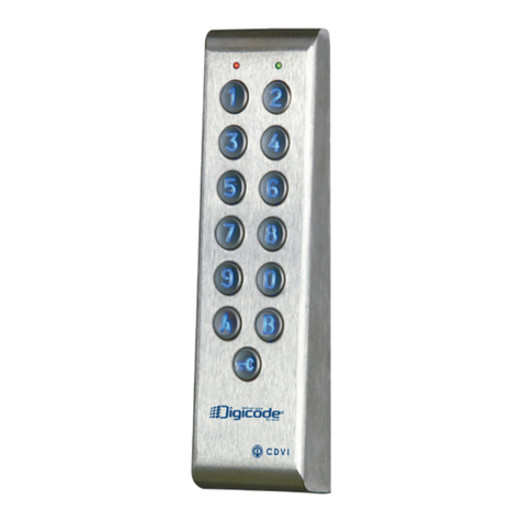
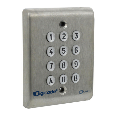
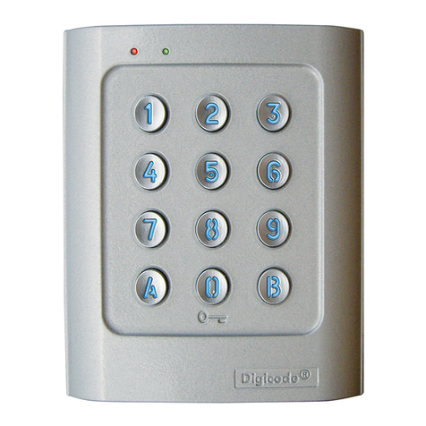
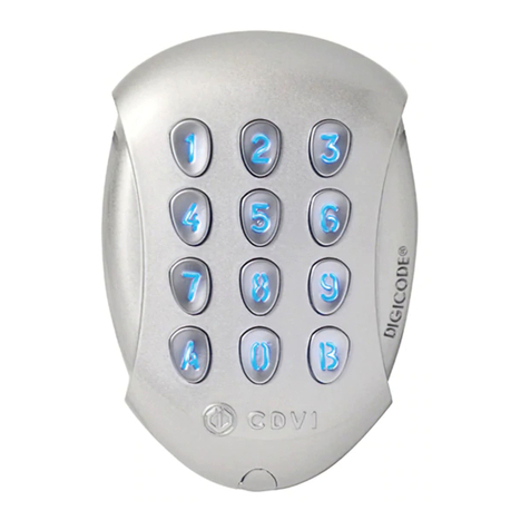
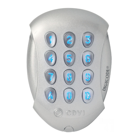
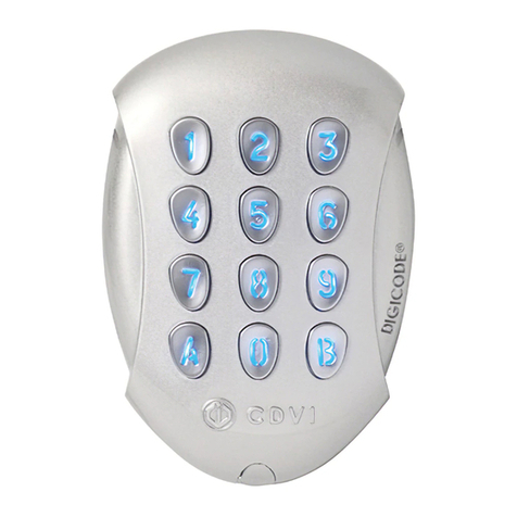
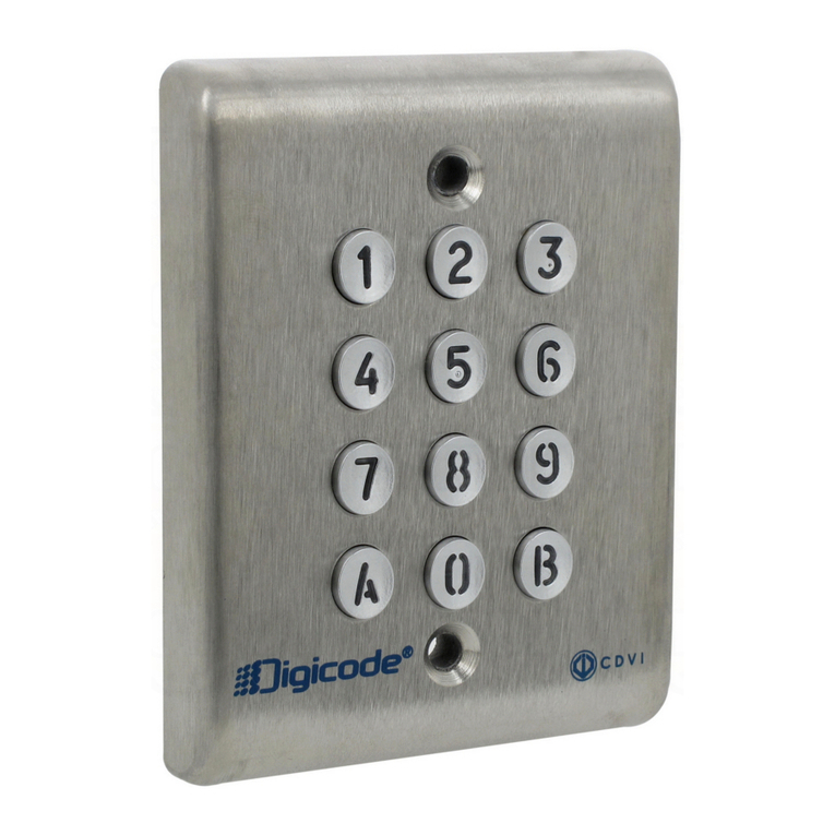
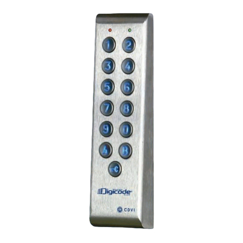
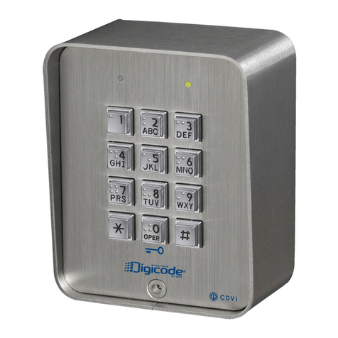
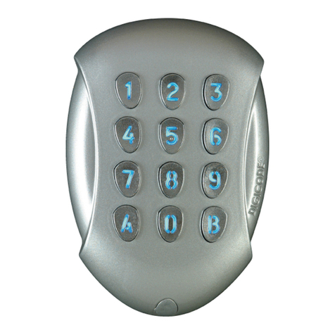
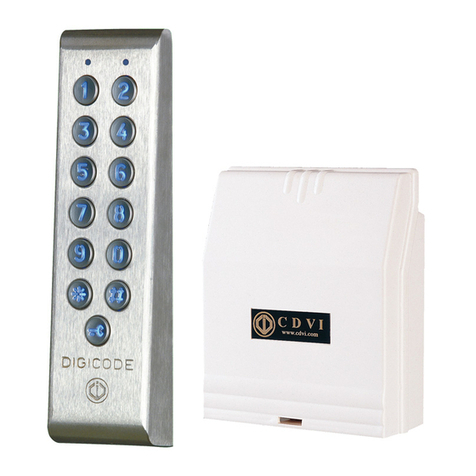
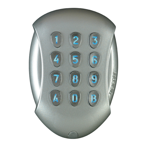
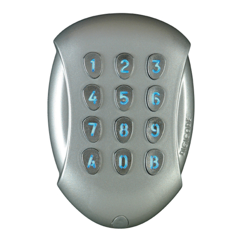
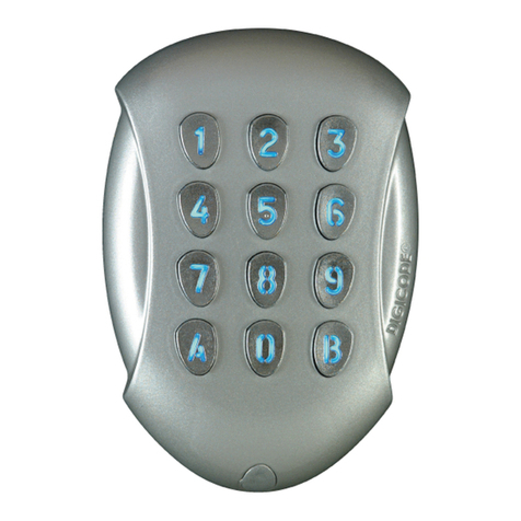
CDVI GALEO 4.0 - Bluetooth User manual

GALEO 4.0 - Bluetooth
BOXCODE
Digicode® zewnętrzna podświetlana klawiatura
z oddzielnym kontrolerem
Weatherproof Illuminated keypad with remote electronics
POLSKI
PL
ENGLISH
EN
4.
Galeo
Le choix de l’installateur
The installer’s choice

1] PODSTAWOWE FUNKCJE
2
Dziękujemy za zakup naszych produktów oraz zaufanie pokładane w naszej rmie.
Digicode® • klawiatura wewnątrz / na zewnątrz – IP64
- trwała polerowana, odlew ze stopu aluminium, wysoka odporność na wandalizm
Zewnętrzny kontroler (BOXCODE)
- Zdalne sterowanie oraz inteligencja w chronionym środowisku, połączona z klawiaturą
przez 3-metrowy kabel
Połączenie plug&play
- Dowolne napięcie:
- 12V —> 24V AC / 12V —> 48V DC
- 3 niezależne wyjścia przekaźnikowe
Intuicyjne programowanie
- 100 kodów użytkowników kongurowalnych przez każdego z użytkowników
Ergonomia
- Sygnalizacja dźwiękowa i wizualna
Łatwe zarządzanie
- Intuicyjne aplikacje dla Administratora i Użytkownika na platformy Android i iOS
Domyślne programowanie
- Brak kodu master w ustawieniach początkowych (możliwe tylko 5 cyfr) .
Możliwość instalacji w 2 opcjach
- obsługa BOXCODE realizowana przez aplikację CDVI
- obsługa BOXCODE realizowana przez aplikację CDVI lub klawiaturę TMGALEO
PL
GALEO 4.0 Bluetooth
Digicode® zewnętrzna podświetlana klawiatura z oddzielnym kontrolerem
INSTRUKCJA INSTALACJI
APLIKACJA
Możliwość dodawania użytkowników za pomocą połączenia Bluetooth twojego Smartfona.
Aplikacja jest dostępna dla systemów Android 5 oraz IOS 8.1 i nowszych wersji. Dostępna do
pobrania ze sklepów Play oraz App Store
6 etapów programowania:
1. Kliknij Kontroler połączony
3. Wprowadź kody
użytkownika dla
przekaźnika 1 (drzwi)
2. Zmień nazwę
kontrolera
cdvigroup.com
Wprowadź kod master
podczas pierwszego użycia
lub połączenia

2] UWAGI I ZALECENIA
Przewód :
Dystans pomiędzy klawiaturą GALEO a sterowni-
kiem nie może przekroczyć 10 metrów.
Upewnij się, czy przewód nie znajduje się w pobliżu
przewodów wysokiego napięcia ( np. 230 V AC ).
Zalecenia dotyczące wyboru przewodu
łączącego GALEO ze sterownikiem :
W celu wydłużenia dostarczonego 3 metrowego
przewodu, wybierz skrętkę 2-żyłową (4-przewody),
SYT1 0.8MM (AWG 20).
Zalecane zasilacze : ADC335 ou BS60
Zalecenia montażowe :
Zamocuj klawiaturę na
płaskiej powierzchni, aby uniknąć zniszczeń w wyniku
wandalizmu, a także zapewnić właściwy montaż.
Wskazówki dotyczące bezpieczeństwa
:
Z przyczyn bezpieczeństwa nie ma kodu master w
ustawieniach fabrycznych(5 cyfr).
Użycie ciągu cyfr 1 2 3 4 5 jest zabronione. Przy
wyborze kodu master oraz kodu użytkownika uni-
kaj kodów sekwencyjnych ( przykład : 3 4 5 6 7 )..
Zabezpieczenie przed zjawiskiem wstecznego
pola elektromagnetycznego (ang. back EMF) :
W celu zabezpieczenia systemu przed zadziałaniem
wstecznego pola elektromagnetycznego nie zapom-
nij zamontować warystora równolegle na elektro-
zamku (nie dotyczy elektrozamków CDVI).
3cdvigroup.com
75
110
15
PL
GALEO 4.0 Bluetooth
Digicode® zewnętrzna podświetlana klawiatura z oddzielnym kontrolerem
INSTRUKCJA INSTALACJI
147
124
56
KONTROLER (BOXCODE)
Zużycie
(przy aktywowanych 3 wyjściach
przekaźnikowych i podświetlonej klawiaturze)
12V 24V 48V
AC 166 mA 82mA -
DC 195 mA 105 mA 54 mA
5. Stwórz prol
użytkownika
4. Ustaw czas
odryglowania
6. Otwórz drzwi za
pomocą przycisku
TMGALEO (OPCJA)
IP64
-25°C do +70°C
Test wibracji
Test mgły solnej
IK10 -25°C do +70°C
IP52

4cdvigroup.com
PL
GALEO 4.0 Bluetooth
Digicode® zewnętrzna podświetlana klawiatura z oddzielnym kontrolerem
INSTRUKCJA INSTALACJI
Warystor Śruba Torx®
(M4x10) Klucz Torx®
(T20) Zaślepki Wkręt
montażowy
(M4x30)
Kołek rozpo-
rowy Uszczelka Uszczelka
Uchwyt
montażowy
sterownika
GALEO - 1 1 1 2 2 - - -
Kontroler 1 - - - 2 2 2 2 1
3] ZESTAW MONTAŻOWY
4] MONTAŻ
GALEO ®
GALEO ®
(x4)
1
GALEO ®
GALEO ®
(x4)
4
GALEO ®
GALEO ®
(x4)
2
GALEO ®
GALEO ®
(x4)
5
GALEO ®
GALEO ®
(x4)
3
GALEO ®
GALEO ®
(x4)
6
Zmierz odległość między klawiaturą
GALEO i sterownikiem ( odniesienie
do strony 3 << Uwagi i zalecenia >>
). Umieść płytkę montażową klawiatury
GALEO oraz wspornik pod zamocowa-
nie sterownika na ścianie, a następnie
zaznacz ołówkiem położenie otworu i
wywierć 2 otwory montażowe (wiertło Ø
5 mm, głębokość otworu 35 mm) oraz
otwór na przeprowadzenie okablowa-
nia.
Przymocuj klawiaturę GALEO do
zainstalowanej płytki przy użyciu
dostarczonej śruby Torx® (M4x10)
i klucza Torx T40. Umieść nakrętkę
na śrubie u dołu klawiatury.
Umieść 2 plastikowe kołki montażowe w
nawierconych otworach. Umieść tylną
płytk montażową klawiatury GALEO i
przykręć ją do ściany za pomocą dos-
tarczonych wkrętów montażowych
(M4x30).
Włóż 2 plastikowe kołki do otworów.
Umieść wspornik przeznaczony na
sterownik i przykręć do ściany za
pomocą dołączonego zestawu śrub
M4x30. Wsuń obudowę od góry do
dołu na wsporniku.
Przełóż przewód przez otwór
w tylnej płytce montażowej
klawiatury. Następnie za-
montuj na niej klawiaturę,
umieszczając najpierw górę
w zaczepach, a później dół
Podłącz przewód do sterownika
za pomocą odpowiednich zacis-
ków na wejściach. Nie zapomnij
zainstalować warystora na elektro-
zamku (patrz strona 3 «Uwagi
i zalecenia »).
BP1
PB1
BP2
PB2
P1P2
230 V AC
Alimentation
Input voltage
12V / 24V AC
12V / 48V DC
Wyjścia Correspondance
WEJŚCIE V
Zasilanie 12V do 24V AC lub 12V do 48V DC
V
Zasilanie 12V do 24V AC lub 12V do 48V DC
DRZWI 1
NC Styk N/C przekaźnika 1
CWspólny przeksźnik 1
NO Styk N/O przekaźnika 1
DRZWI 2
NC Styk N/C przekaźnika 2
CWspólny przeksźnik 2
NO Styk N/O przekaźnika 2
DRZWI 3
NC Styk N/C przekaźnika 3
CWspólny przeksźnik 3
NO Styk N/O przekaźnika 3
Przycisk
PB1 Wejście przekaźnika 1 dla przycisku wyjścia
M Wspólne wejścia
PB2 Wejście przekaźnika 2 dla przycisku wyjścia
Zegar
PX Nie używane
HNie używane
H Styk Timera
Klawitura
Digicode®
TMGALEO
+Biały przewód z klawiatury
-Brązowy przewód z klawiatury
EZielony lub niebieski (podświetlenie)
5] SCHEMAT POŁĄCZEŃ GALEO, 3 WYJŚCIA PRZEKAŹNIKOWE
Wejście PB1 dla przycisku wyjścia aktywuje
przekaźnik 1. .
Wejście PB2 dla przycisku wyjścia
aktywuje przekaźnik 2.
Wyjście bistabilne lub monostabilne.
Wejście H może być używane z timerem,
aby zapewnić swobodny dostęp przez
naciśnięcie dowolnego przycisku na klawia-
turze.
Gdy styk jest otwarty, przycisk wejścia jest
zablokowany.
Gdy styk jest zwarty, naciśnij dowolny
klawisz na klawiaturze, aby wejść
.
Kontroler
Zworka P2 pozwala
użytkownikowi
zmodykować swój kod
PIN. W celu aktywacji
tej funkcji nałóż zworkę
Zworka P1 resetuje
klawiaturę do wartości
ustawień fabrycznych.
Odłącz klawiaturę od zasi-
lania, a następnie umieść
zworkę
5cdvigroup.com
PL
GALEO 4.0 Bluetooth
Digicode® zewnętrzna podświetlana klawiatura z oddzielnym kontrolerem
INSTRUKCJA INSTALACJI

6] SCHEMAT PROGRAMOWANIA
Wpisz dwukrotnie
kod master
2 sygnały dźwiękowe (bip)
1 bip
1 bip = OK
(4 bips = Błąd)
10-99 sek
00 = ciągłe
10 = Domyślnie
A0
Czas podświetlenia
1 bip
1 bip = OK
(4 bips = Błąd)
01-99 sek
00 = ciągłe
01 = Domyślnie
A2
Czas aktywacji
przekaźnika 2
1 bip
1 bip = OK
(4 bips = Błąd)
01-99 sek
00 = ciągłe
01 = Domyślnie
A1
Czas aktywacji
przekaźnika 1
1 bip
1 bip = OK
(4 bips = Błąd)
01-99 sek
00 = ciągłe
01 = Domyślnie
A3
Czas aktywacji
przekaźnika 3
1 bip
1 bip = OK
(4 bips = Błąd)
4’ lub 5’
cyfr
5 = Domyślnie
A4
Długość kodu
1 bip
1 bip = OK
(4 bips = Błąd)
Zmień kod Master
12345=
NIE
A5
Kod Master
6cdvigroup.com
PL
GALEO 4.0 Bluetooth
Digicode® zewnętrzna podświetlana klawiatura z oddzielnym kontrolerem
INSTRUKCJA INSTALACJI
Przekaźniki GALEO 3
Przekaźnik 1 : od 00 do 59,
Przekaźnik 2 : od 60 do 79,
Przekaźnik 3 : od 80 do 99.
PAMIĘTAJ
Dodatkowe informacje znajdziesz na stronie 8.

2 bips
1 bip
A6
Reset
1 bip
1 bip = OK
(4 bips = Błąd)
2
cyfry
AB=domyślnie
A7
Kod Sub Master
przekaźnik 1
1 bip
1 bip = OK
(4 bips = Błąd)
2
cyfry
13=domyślnie
A8
Kod Sub Master
przekaźnik 2
1 bip
1 bip = OK
(4 bips = Błąd)
2
cyfry
46=domyślnie
A9
Kod Sub Master
przekaźnik 3
1 bip
1 bip = OK
(4 bips = Błąd)
0 = Buzer
wyłączony
1 = Buzer
włączony
AA
Buzer
(powiadomienie
dźwiękowe)
1 bip = OK
4’ lub 5’ cyfry
------------------
4 bips =
Kod już używany
00-99
Kody użytkowników
B
A
7cdvigroup.com
PL
GALEO 4.0 Bluetooth
Digicode® zewnętrzna podświetlana klawiatura z oddzielnym kontrolerem
INSTRUKCJA INSTALACJI
B

PL
GALEO 4.0 Bluetooth
Digicode® zewnętrzna podświetlana klawiatura z oddzielnym kontrolerem
INSTRUKCJA INSTALACJI
7] PROGRAMOWANIE
8cdvigroup.com
A. UŻYCIE PO RAZ PIERWSZY LUB W PRZYPADKU RESETU
1. Włącz system :
Na kontrolerze :
- Zapala się zielona dioda LED
- Następnie zapala się czerwona dioda LED
- Następnie czerwona i zielona dioda LED migają
Na klawiaturze :
- Wyemitowany zostanie 1 sygnał dźwiękowy
- Klawiatura świeci się i miga
2. Wprowadź dwukrotnie nowy kod Master ( jedynie 5 cyfr ).
Sekwencja cyfr 12345 jest zabroniona w przypadku kodu Master
- Klawiatura przestaje migać
- Po pierwszym wprowadzeniu kodu Master klawiatura błyśnie 1 raz
- Wprowadź kod Master po raz drugi
- Jeśli kod został wprowadzony poprawnie w obu próbach, emitowane są 2 sygnały dźwiękowe.
W przeciwnym razie poczekaj, aż klawiatura zacznie migać ponownie, aby dwukrotnie
wprowadzić nowy kod (około 10 sekund)
- Wprowadzanie w trybie programowania
3. Skonguruj system zgodnie ze schematem programowania
- Naciśnij przycisk B, aby wyjść z trybu programowania
B. RESET PAMIĘCI
1. Odłącz zasilanie i załóż zworkę na P1
(strona 5).
2. Z powrotem podłącz zasilanie :
Na kontrolerze :
- Czerwona dioda LED zapalona podczas resetowania
- Po resecie czerwone i zielone diody LED nadal migają podczas oczekiwania na nowy
kod główny
Na klawiaturze :
- Podczas resetowania emitowanych jest 6 krótkich sygnałów dźwiękowych, a na końcu
1 długi sygnał
- Klawiatura nadal miga podczas oczekiwania na nowy kod główny

PL
GALEO 4.0 Bluetooth
Digicode® zewnętrzna podświetlana klawiatura z oddzielnym kontrolerem
INSTRUKCJA INSTALACJI
3. Wyciągnij zworkę na P1.
- Kod Master oraz kody użytkowników zostaną usunięte, a ustawienia powrócą do wartości
domyślnych
4. Rozpocznij ponownie od części A
C. RESET KODU MASTER
W trybie gotowości załóż zworkę na P1. Poczekaj, aż klawiatura zacznie migać, aby
wprowadzić nowy kod główny
Na kontrolerze :
- Czerwona dioda LED zapalona podczas resetowania
- Po resecie czerwone i zielone diody LED nadal migają podczas oczekiwania na
nowy kod główny
Na klawiaturze :
- podczas resetowania kodu Master emitowane są 3 krótkie sygnały dźwiękowe, a
następnie 1 długi sygnał
- Klawiatura miga podczas oczekiwania na wprowadzenie nowego kodu Master
D. ZMIANA KODU PRZEZ UŻYTKOWNIKA
W celu upoważnienia użytkownika do modykacji swojego kodu, należy umieścić zworkę na
P2 ( usunięcie zworki blokuje tę funkcje ).
1. Wprowadź aktualny kod użytkownika
- Przekaźnik jest aktywowany i emitowany jest sygnał dźwiękowy
2. Wprowadź 2-cyfrowy kod podrzędny
- Przekaźnik 1, domyślny kod podrzędny : A i B
- Przekaźnik 2, domyślny kod podrzędny: 1 i 3
- Przekaźnik 3, domyślny kod podrzędny: 4 i 6
- W celu potwierdzenia modykacji zostanie wyemitowany sygnał dźwiękowy
3. Wprowadź nowy kod użytkownika
- W celu potwierdzenia nowego kodu wyemitowane zostaną 2 sygnały dźwiękowe
4. Sprawdź nowy kod użytkownika, aby sprawdzić poprawność modykacji
9cdvigroup.com

Digicode® indoor/outdoor - IP64 (keypad)
- Polished heavy duty Zamak® cast alloy, high resistance to vandalism
Remote controller
- remote controller and intelligence in a protected environment and connected with 3m cable
Plug’n’play connection
- Free voltage
- 12V to 24Vac and 12V to 48Vdc
- 3 independent relay outputs
Intuitive programming
- 100 user codes customisable by each user
Ergonomic
- Audible and visual feedback
Default programming
There is no master code in the factory setting (only 5 terms)
2 mounting available
- Operation of the BOXCODE perform with CDVI App
- Operation of the BOXCODE with CDVI App or TMGALEO keypad
1] KEY FEATURES
Thank you for buying our products and for the condence you placed
in our company.
EN
GALEO 4.0 Bluetooth
Weatherproof Illuminated Keypad with remote electronics
INSTALLATION MANUAL
10 cdvigroup.com
THE APPLICATION
You have a possibility to add users with the Bluetooth connection and your Smartphone.
This app is available from Android 5 and IOS 8.1
6 steps about programming :
1. Press
connected box
3. Change user
codes relay 1
(door)
2. Change the box
name
enter the master code
during the rst use
or connection

2] NOTES & RECOMMENDATIONS
Cable :
The distance between the GALEO and the remote
electronic can not exceed more than 10 meters.
Make sure that the cable is not near by a high
voltage cables (ex: 230 V AC).
Recommended cable between the GALEO
and the remote electronic :
To expand the supplied 3 meter cable, select a 2
twisted pairs cable (4 wires), SYT1 0.8MM (AWG 20).
Recommended power supplies suitable
for the GALEO :
ADC335 (230V input) or BS60 (230V input).
Mounting recommendations :
Mount the keypad on a at surface to avoid any
vandalism and to insure the best mounting.
Security advice :
For security advice reasons, there is no master
code in the factory setting (only 5 terms).
The 1 2 3 4 5 code is forbidden as a master code.
When selecting a master code and user code avoid
sequencial codes (example : 3 4 5 6 7).
Back EMF protection :
To secure the system from back electromagnetic
elds do not forget to mount the varistor in parallel
on the lock.
EN
GALEO 4.0 Bluetooth
Weatherproof Illuminated Keypad with remote electronics
INSTALLATION MANUAL
147
124
56
75
110
15
REMOTE CONTROLLER (BOXCODE)
Consumption
(3 relay outputs activated and
keypad illuminated)
12V 24V 48V
AC 166mA 82 mA -
DC 195 mA 105 mA 54 mA
TMGALEO (OPTIONAL)
5. Create
user sheet
4. Unlock time
conguration 6. Open the door
with the button
11cdvigroup.com
IP64
-25°C to +70°C
Vibrations tests
Salt spray
IK10 -25°C to +70°C
IP52

12 cdvigroup.com
EN
GALEO 4.0 Bluetooth
Weatherproof Illuminated Keypad with remote electronics
INSTALLATION MANUAL
3] MOUNTING KIT
4] MOUNTING
GALEO ®
GALEO ®
(x4)
1
GALEO ®
GALEO ®
(x4)
4
GALEO ®
GALEO ®
(x4)
2
GALEO ®
GALEO ®
(x4)
5
GALEO ®
GALEO ®
(x4)
3
GALEO ®
GALEO ®
(x4)
6
Verify the distance between the
GALEO keypad and its remote
electronic (Refer to page 3 «Notes and
Recommendations»). Place the back
plate of the GALEO on the wall and
the bracket of the remote electronic
then mark with a pen the hole location
then drill the 2 mounting holes (drill bit
Ø 5 mm and 35 mm hole depth)
and the hole wiring access.
Fasten the GALEO keypad to the back
plate by using the supplied (M4x10)
Torx® screw and T20 Trox spanner
hardware. Place the screw cap at the
bottom of the keypad.
Insert the 2 plastic anchors in the
holes. Place the back plate of the
GALEO and screw on the wall using
the supplied (M4x30) mounting
screws.
Insert the 2 plastic anchors in the holes.
Place the bracket of the electronic
and screw on the wall using the supplied
M4x30 screws. Slide the box from up
to down on the bracket.
Insert the cable in the hole access
area of the back plate. Then mount
the keypad on the back plate,
placing rst the top in the hooks
and then the bottom.
Insert the cable in the remote electronic
and wire the cable to the terminals.
Do not forget to install the varistor
on the lock (Refer to page 3 «Notes
and Recommendations»).
Varistor (M4x10)
Torx®
screw
T20 Torx®
Spanner Caps (M4x30)
mounting
screws
Plastic
anchors
Wiring
sealed
cap
Wiring
sealed
cap
Mounting
plate for
remote
electronic
box
GALEO - 1 1 1 2 2 - - -
Remote
Controller 1 - - - 2 2 2 2 1

BP1
PB1
BP2
PB2
P1P2
230 V AC
Alimentation
Input voltage
12V / 24V AC
12V / 48V DC
5] WIRING DIAGRAM GALEO 3 RELAY OUTPUTS
13cdvigroup.com
EN
GALEO 4.0 Bluetooth
Weatherproof Illuminated Keypad with remote electronics
INSTALLATION MANUAL
Remote electronics
P2 jumper allows
to the user to modify
its own Pin code.
To enable this feature put
the jumper on.
P1 jumper resets the
keypad to factory default
values. Remove the power
from the keypad then put
the jumper.
PB1 request-to-exit input activates relay 1.
PB2 request-to-exit input activates relay 2.
Latch or toggled output.
H input can be used with a timer to enable
free access by pressing on any digit key on
the keypad.
When the contact is open
then the request-to-enter is disabled.
When the contact is closed then press any
key on the keypad to enter.
Outputs Wiring table
INPUT
V
Input voltage 12V to 24VAC or 12V to 48VDC
V
Input voltage 12V to 24VAC or 12V to 48VDC
DOOR 1
NC N/C contact relay 1
CCommon relay 1
NO N/O contact relay 1
DOOR 2
NC N/C contact relay 2
CCommon relay 2
NO N/O contact relay 2
DOOR 3
NC N/C contact relay 3
CCommon relay 3
NO N/O contact relay 3
Push
button
PB1 Request-to-exit input relay 1
MCommon of inputs
PB2 Request-to-exit input relay 2
Clock
PX Not used
HNot used
HTimer Contact
Keypad
TMGALEO
+ White wire from keypad
-Brown wire from keypad
EGreen or Blue wire (illumination)

14 cdvigroup.com
6] PROGRAMMING CHART
Enter Master
code twice
2 x beeps
1 x beep
1 x beep = OK
4 beeps = Error
10-99 sec
00 = permanent
10=Default
A0
Illumination
duration
1 x beep
1 x beep = OK
4 beeps = Error
01-99 sec
00 = toggled
01=Default
A2
Time Relay 2
1 x beep
1 x beep = OK
4 beeps = Error
01-99 sec
00 = toggled
01=Default
A1
Time Relay 1
1 x beep
1 x beep = OK
4 beeps = Error
01-99 sec
00 = toggled
01=Default
A3
Time Relay 3
1 x beep
1 x beep = OK
4 beeps = Error
4’ or 5’
digits
5=Default
A4
Code length
1 x beep
1 x beep = OK
4 beeps = Error
Change master
code
12345=prohibited
A5
Master code
EN
GALEO 4.0 Bluetooth
Weatherproof Illuminated Keypad with remote electronics
INSTALLATION MANUAL
GALEO Relays 3 (3 outputs)
Relay 1 : From 00 to 59,
Relay 2 : From 60 to 79,
Relay 3 : From 80 to 99.
REMINDER
Find the additional informations page 16.

15cdvigroup.com
2 x beeps
1 x beep
A6
Reset
1 x beep
1 x beep = OK
4 beeps = Error
2
digits
AB=default
A7
Sub master code 1
1 x beep
1 x beep = OK
4 beeps = Error
2
digits
13=default
A8
Sub master code 2
1 x beep
1 x beep = OK
4 beeps = Error
2
digits
46=default
A9
Sub master code 3
1 x beep
1 x beep = OK
4 beeps = Error
0= Buzzer disabled
1 = Buzzer
enabled
AA
Buzzer
(Audible feedback)
1 x beep = OK
4’ or 5’ digit code
------------------
4 beeps = User
location: “used”
00-99
User codes
B
A
EN
GALEO 4.0 Bluetooth
Weatherproof Illuminated Keypad with remote electronics
INSTALLATION MANUAL
B
Find the additional informations page 16.

7] PROGRAMMING
16 cdvigroup.com
A. FIRST USE OR AFTER RESET
1. Power up the system
On the remote electronics:
- Green LED lights on
- Then the Red LED lights on
- Then the Red and Green LED ash
On the keypad:
- 1 beep is emitted
- The keypad lights on and ashes
2. Enter a new code twice for the master code (only 5 terms).
The 12345 code is forbidden in master code.
- The keypad stop ashing
- After the rst entry of the master code, the keypad ashes 1 time
- Enter the second entry of the master code
- If both entry of the master code are the same, 2 beeps are emitted.
Otherwise, wait until the keypad ashes again to enter the new master code twice
(about 10 seconds)
- Entry in programming mode
3. Congure the system with the programming chart
- Press B to exit from programming mode
B. RESET MEMORY
1. Cut off the power and put the jumper on P.
- Refer to page 13 for the jumper P1 on the remote electronics
2. Put the power back :
On the remote electronics:
- Red LED lights on during reset
- After the reset, Red and Green LEDs still ashing while waiting new master code
On the Keypad:
- 6 short beeps are emitted during reset and at the end 1 long beep is emitted
- The keypad still ashing while waiting new master code
3. Pull out the jumper on P1
- Master code and user codes are cleared and set to default value
4. Start again from part A
EN
GALEO 4.0 Bluetooth
Weatherproof Illuminated Keypad with remote electronics
INSTALLATION MANUAL

C. RESET MASTER CODE
On stand-by operating mode, put a jumper on P1. Wait until the keypad ashes to enter new
master code.
On the remote electronics:
- Red LED lights on during the reset of the master code
- Then Green LED lights on
On the keypad:
- 3 short beeps are emitting during the reset of the master code and after that
1 long beep is emitted
- The keypad ashes while waiting the entry of a new master code
D. CHANGING THE CODE BY A USER
To authorize a user to modify its own user code, put a jumper on P2 (to disable the feature,
remove the jumper)
1. Enter the current user code
- The relay is activated and a beep is emitted
2. Enter the 2 digits sub master code
- Relay 1, default sub master code: A and B
- Relay 2, default sub master code: 1 and 3
- Relay 3, default sub master code: 4 and 6
- A beep is emitted to authorize the modication
3. Enter the new user code
- 2 beeps are emitted to conrm the new code
4. Check the new user code to be sure of the modication
17cdvigroup.com
EN
GALEO 4.0 Bluetooth
Weatherproof Illuminated Keypad with remote electronics
INSTALLATION MANUAL

18 cdvigroup.com
NOTES
PL
GALEO 4.0 Bluetooth
Digicode® zewnętrzna podświetlana klawiatura z oddzielnym kontrolerem
INSTRUKCJA INSTALACJI

19cdvigroup.com
Tabela podsumowująca, która posłuży do wskazania kodu przypisanego każdemu
użytkownikowi oraz zaprogramowania kodów użytkowników.
Numer
Użytk. Kod Nazwa
00
01
02
03
04
05
06
07
08
09
10
11
12
13
14
15
16
17
18
19
20
21
22
23
24
25
26
27
28
29
30
31
32
33
Numer
Użytk. Kod Nazwa
34
35
36
37
38
39
40
41
42
43
44
45
46
47
48
49
50
51
52
53
54
55
56
57
58
59
60
61
62
63
64
65
66
67
Numer
Użytk. Kod Nazwa
68
69
70
71
72
73
74
75
76
77
78
79
80
81
82
83
84
85
86
87
88
89
90
91
92
93
94
95
96
97
98
99
GALEO 3 Przekaźniki
Przekaźnik 1 : od 00 do 59,
Przekaźnik 2 : od 60 do 79,
Przekaźnik 3 : od 80 do 99.
GALEO Relays 3 (3 outputs)
Relay 1 : From 00 to 59,
Relay 2 : From 60 to 79,
Relay 3 : From 80 to 99.
Pamiętaj
19cdvigroup.com
PL
GALEO 4.0 Bluetooth
Digicode® zewnętrzna podświetlana klawiatura z oddzielnym kontrolerem
INSTRUKCJA INSTALACJI

Le choix de l’installateur
Reference : G0301FR0234V13
Extranet : CDVI_IM GALEO4.0 CMYK A5 PL-EN 13
All the information contained within this document (pictures, drawing, features, specications and dimensions) could be perceptibly different and can be changed without prior notice.
Wszystkie informacje zawarte w niniejszym dokumencie (zdjęcia, rysunki, cechy, specykacje oraz wymiary) mogą być rozbieżne i mogą zostać zmienione bez ostrzerzenia.
*G0301FR0234V13*
CDVI Group
FRANCE (Siège social/Headquarter)
Phone: +33 (0)1 48 91 01 02
CDVI SAS
FRANCE + EXPORT
31, av. du Général Leclerc
93500 PANTIN - France
Phone: +33 (0)1 48 91 01 02
www.cdvi.com
CDVI AMERICAS
[CANADA - USA]
Phone: +1 (450) 682 7945
www.cdvi.ca
CDVI BENELUX
[BELGIUM - NETHERLAND - LUXEMBOURG]
Phone: +32 (0) 56 73 93 00
www.cdvibenelux.com
CDVI TAIWAN
Phone: +886 (0)42471 2188
www.cdvichina.cn
CDVI SUISSE
Phone: +41 (0)21 882 18 41
www.cdvi.ch
CDVI CHINA
Phone: +86 (0)10 84606132/82
www.cdvichina.cn
CDVI IBÉRICA
[SPAIN - PORTUGAL]
Phone: +34 (0)935 390 966
www.cdviberica.com
CDVI ITALIA
Phone: +39 0321 90 573
Fax: +39 0321 90 8018
www.cdvi.it
CDVI MAROC
Phone: +212 (0)5 22 48 09 40
www.cdvi.ma
CDVI SWEDEN
[SWEDEN - DENMARK - NORWAY - FINLAND]
Phone: +46 (0)31 760 19 30
www.cdvi.se
CDVI UK
[UNITED KINGDOM - IRELAND]
Phone: +44 (0)1628 531300
www.cdvi.co.uk
CDVI POLSKA
Phone: +48 12 659 23 44
Fax: +48 12 257 11 10
www.cdvi.com.pl
Other manuals for GALEO 4.0 - Bluetooth
3
Table of contents
Languages:
Other CDVI Keypad manuals

CDVI
CDVI GALEO/W User manual

CDVI
CDVI Digicode PROFIL100EC User manual

CDVI
CDVI DC100E User manual

CDVI
CDVI Digicode Series User manual

CDVI
CDVI SUBLIM User manual

CDVI
CDVI Galeo User manual

CDVI
CDVI CBB User manual

CDVI
CDVI KCIN User manual

CDVI
CDVI PROFIL100EINT User manual

CDVI
CDVI PROMI E Quick start guide
Popular Keypad manuals by other brands

Tunstall
Tunstall Keypad Installer Quick Reference Card

Genie
Genie Wireless Keypad-IC Installation and programming instructions

Linear
Linear LINEAR ENC-DRS installation instructions

SOMFY
SOMFY CLAVIER TOUCHE FILAIRE installation guide

Steren
Steren COM-626 user manual

Honeywell
Honeywell ADEMCO 6160RF user guide