Labels
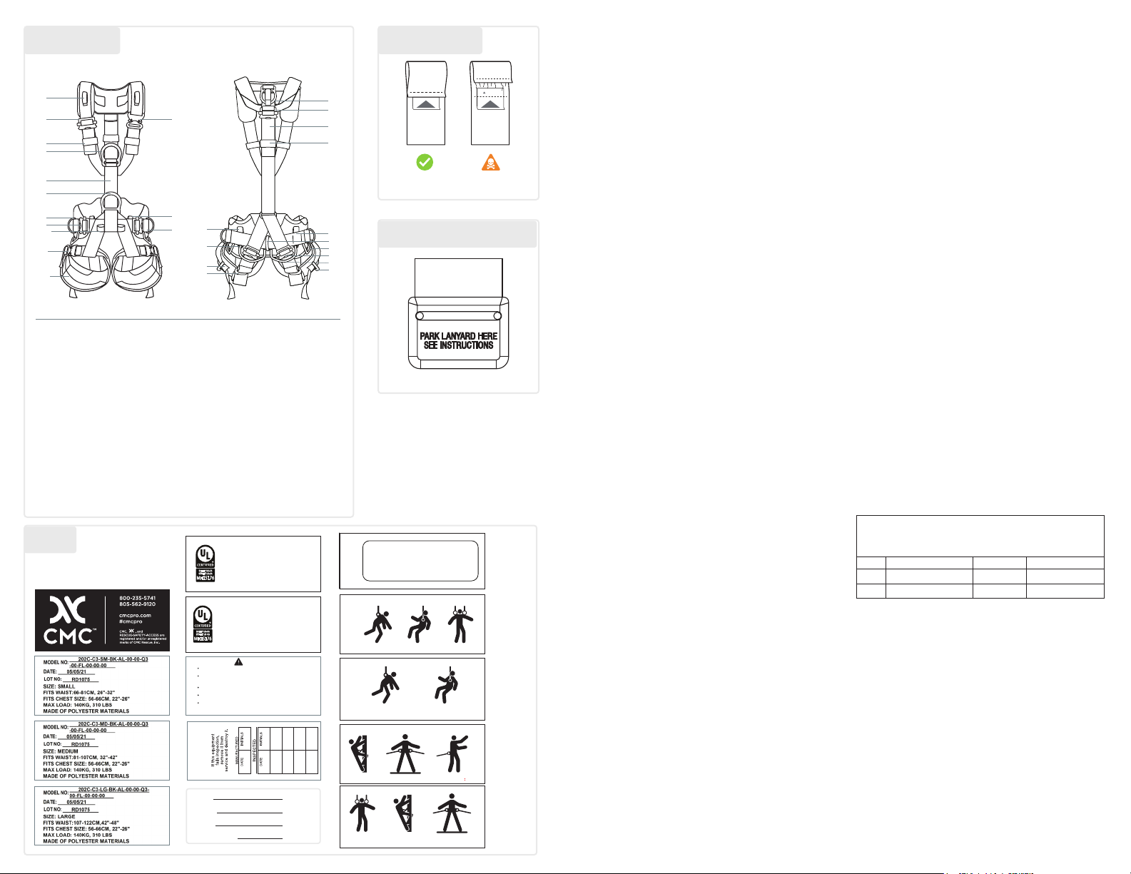
Nomenclature
USER INFORMATION
User Information shall be provided to the user of the product. NFPA Standard
1983, incorporated into the 2022 edition of NFPA 2500 recommends
separating the User Information from the equipment and retaining the
information in a permanent record. The standard also recommends making
a copy of the User Information to keep with the equipment and that the
information should be referred to before and after each use.
Additional information regarding life safety equipment can be found in NFPA
1500 and NFPA 1858 and NFPA 1983, incorporated in the 2022 edition
of NFPA 2500 and the ANSI Z359 and CSA Z259 series of Fall Protection
standards.
LIFESPAN / INSPECTION / RETIREMENT
The equipment has a lifespan of 10 years from the date of manufacture shown
on the product label. The type of use, intensity of use, and environment of
use are all factors in determining serviceability of the equipment. A single
exceptional event can be cause for retirement after only one use, such
as exposure to sharp edges, extreme temperatures, chemicals, or harsh
environments. Any concerns about its safe use is cause for retirement.
Remove retired equipment from service and destroy it to prevent further use.
A device must be retired when it fails to pass inspection; it fails to function
properly; it has illegible product labels or markings; it shows signs of damage
or excessive wear; it has been subjected to shock loads, falls, or abnormal
use; it has been exposed to harsh chemical reagents; it has an unknown
usage history; you have any doubt as to its condition or reliability; or when
it becomes obsolete due to changes in legislation, standards, technique or
incompatibility with other equipment.
Inspect the equipment according to your department’s policy for inspecting
life safety equipment. CMC recommends a detailed inspection by a
competent person at least once every 12 months depending on current
regulations and conditions of use. Record the date, inspector name,
and inspection results in the equipment log as well as any other relevant
information to track the usage history.
When inspecting the equipment, conrm it is functioning properly and verify
the presence and legibility of labels and markings. Check soft components
for cuts, worn or frayed areas, broken bers, soft or hard spots, discoloration,
or melted bers. Check the stitching for pulled threads, abrasion, or breaks.
Check hardware for excessive wear or indications of damage such as
deformation, corrosion, sharp edges, cracks, or burrs. Minor nicks or sharp
spots may be smoothed with emery cloth or similar. Check for the presence
of dirt or foreign objects that can affect or prevent normal operation Conrm
all pieces of equipment in the system are correctly positioned with respect to
each other and monitor the condition of the equipment and its connections.
Do not allow anything to interfere with the proper operation of the equipment.
Visual Indicator: Prior to donning the harness, inspect the visual indicator
located in proximity of the dorsal attachment point. If the visual indicator is
damaged or shows signs of deployment, remove the harness from service.
LIMITATIONS AND PROPER USE
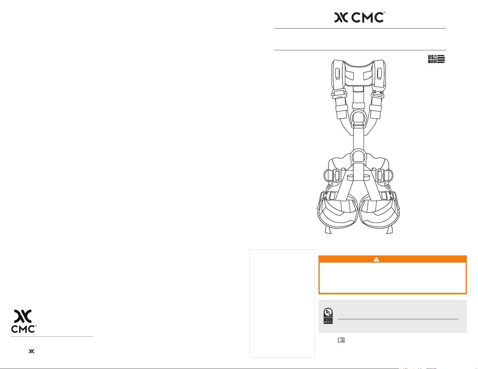
The ATOM Harness is designed for optimum performance, dependability,
and comfort in rescue and work positioning applications. Its low-prole
construction and supportive architecture provides excellent mobility on rope
and on the ground. When using the ATOM Harness, follow best practices
for avoiding high impact falls. Always keep the safety line (belay) above the
wearer and keep the slack in the safety line to a minimum. To ensure the
safety and comfort of your ATOM Harness, make sure it is properly sized and
adjusted per the instructions below. Depending on the conguration of the
harness, not all attachment elements outlined in this user guide apply.
CMC warns against using the equipment around moving machinery and
electrical hazards.
Rescue: NFPA 1983, incorporated into the 2022 edition of NFPA 2500
provides specications for a rescue harness. All front and back D-ring
connection points are dynamically and statically tested, and independently
certied to this standard.
Rope Access Work: A harness selected for rope access work needs
comfort and support very similar to a rescue harness, which is not available
in a harness designed solely for fall arrest applications. Depending on the
applicable regulations, fall protection may also be required.
Fall Protection: Harnesses designed for fall protection must meet the
requirements of ANSI Z359.11 and CSA Z259.10. All attachment points are
independently certied to these standards. When using this equipment the
user shall have a rescue plan and the means at hand to implement it when
using the harness for fall arrest.
To prevent roll out when using carabiners to attach to an attachment
point, use only locking models. If using manual locking carabiners, verify
that they are locked before use. It is the users responsibility to verify
equipment compatibility with components and sub-systems before use.
Consult with the current edition of ANSI/ASSP Z359.11 / CSA Z259.10 and
applicable state or provincial regulations governing occupational safety. The
user should consider all component extensions and allow clearance for an
arrest to take place a safe distance away from the ground or structure. A
harness stretch factor of up to 18 inches (46 cm) should be factored in while
calculating fall clearance.
PUTTING ON YOUR HARNESS
• Loosen all the harness straps for easy donning, including waist belt, leg
loops, and shoulder strap (disconnect quick-connect buckles if present).
• Hold shoulder straps to the side and step through the waist belt, putting
each foot into the proper leg loop.
• Position the waist belt and ventral attachment point above the waistline.
• Tighten the waist belt by pulling both sides simultaneously until the waist
is snug, and the front D-ring is centered.
• Position the dorsal attachment point level with shoulder blades and
adjust back strap.
• Position the sternal attachment point as high as possible and adjust
shoulder straps on each side.
• Tighten the rear leg straps, this is especially important when using the
dorsal point.
• Position the leg loops with padding along back and side of legs.
• Tighten leg loops, leaving about a nger width of space between the leg
loops and the legs.
• Before use, conrm all straps are tight, stow excess web in elastic
keepers and apply load to the sternal attachment point and conrm
position of all D-rings.
A suspension test should be carried out in a safe place prior to putting the
harness in service. A suspension test will verify that the harness is the correct
size, has sufcient adjustment and is of an acceptable comfort level for the
intended use.
WARNING: Make sure the straps are snug. This increases the comfort
when sitting in the harness and helps prevent the quick-connect buckles
from disconnecting. When wearing the harness, double-check the
buckles, adjusters, and t of the harness immediately prior to relying on
it for support.
LANYARD PARKING ELEMENT
If using a fall arrest lanyard or Y-lanyard, connect the lanyard snaphook to
the parking element located on the shoulders of the harness when not in use
(unless otherwise connected to an anchorage point). The lanyard parking
element of the harness is intended to disengage in the event that the lanyard
is hung up or tangled during a fall or during normal use creating a hazard.
CARRYING, MAINTENANCE & STORAGE
During use, carrying, storage, and transport keep the equipment away
from acids, alkalis, exhaust emissions, rust and strong chemicals. Do not
expose the equipment to direct heat, ame, or high temperatures or other
adverse environmental conditions. If the equipment becomes soiled, it can
be washed in cold water with a mild detergent that is safe for use with nylon
and polyester. Rinse thoroughly. Do not use a pressure washer. Air dry in
temperatures between 10° C and 30° C. Do not dry the equipment in direct
sunlight or using an automatic dyer. Lubricate moving parts as needed.
During storage and transport, protect the equipment from heat, direct
sunlight, moisture, chemicals, and external loads or impacts. Do not store
where equipment may be exposed to moist air, particularly where dissimilar
metals are stored together. Consult with manufacturer in case of any doubt.
WARRANTY & REPAIRS
If your CMC product has a defect due to workmanship or materials,
information and service. CMC’s warranty does not cover damages caused
by improper care, improper use, alterations and modications, accidental
damage or the natural breakdown of material over extended use and time.
All repair work shall be performed by the manufacturer. All other work or
modications void the warranty and releases CMC from all liability and
responsibility as the manufacturer.
SAMPLE INSPECTION AND MAINTENANCE LOG
The following sample log provides an example of the records that should be
maintained by the purchaser or user of life safety equipment.
EQUIPMENT INSPECTION AND MAINTENANCE LOG
Item______________#______ Date in Service________
Brand/Model_________________ Strength___________
Date How Used or Maintained Comments Name
ANNEX A - NORMATIVE
Note: The following information from the ANSI/ASSP Z359.11 standard
is required to be included in the instruction manual for the end user. The
manufacturer of this equipment may impose more stringent restrictions
on the use of the products they manufacture; see the manufacturer’s
instructions.
1. It is essential that the users of this type of equipment receive proper
training and instruction including detailed procedures for the safe
use of such equipment in their work application. ANSI/ASSP Z359.2,
Minimum Requirements for a Comprehensive Managed Fall Protection
Program, establishes guidelines and requirements for an employer’s
managed fall protection program including policies, duties and
training; fall protection procedures; eliminating and controlling fall
hazards; rescue procedures; incident investigations; and evaluating
program effectiveness.
2. Correct t of a full body harness (FBH) is essential to proper
performance. Users must be trained to select the size and maintain the
t of their FBH.
3. Users must follow manufacturer’s instructions for proper t and sizing,
paying particular attention to ensure that buckles are connected and
aligned correctly, leg straps and shoulder straps are kept snug at all
times, chest straps are located in the middle chest area and leg straps
are positioned and snug to avoid contact with the genitalia should a
fall occur.
4. FBHs which meet ANSI/ASSP Z359.11 are intended to be used with
other components of a personal fall arrest system that limit maximum
arrest forces to 1800 pounds (8kN) or less 5. Suspension intolerance,
Visual Indicator
WARNING
!
Lanyard Parking Element
1 Lanyard parking element
2 Shoulder strap adjustment buckle
3 Quick-release shoulder strap
adjustment buckle
(varies by model)
4 Elastic keepers for straps (multiple
locations)
5 Sternal attachment point
(“A” label)
6 Chest ascender location (ascender kit
sold separately)
7 Ventral attachment point
8 Side work-positioning attachment points
(varies by model)
9 Adjustment buckles for waist straps
10 Work seat connection loops
(work seat sold separately)
11 Quick-release leg strap adjustment
buckles
(varies by model)
12 Leg loops
13 Dorsal attachment point
14 Adjustment buckle for rear strap
15 Visual indicator
16 Tool carrier attachment point
(tool carrier sold separately)
17 Rear travel restraint point
18 Gear loops
(10 kg max, varies by model)
19 Adjustment buckles for leg loop link
strap
20 Tool loops (10 kg max)
21 Accessory attachment points
(10 kg max)
1
2
4
5
6
7
8
9
10
11
12
3
21
4
13
14
15
4
21
21
4
4
16
17
18
19
20
20
000120_Rev02
3.625” (92.075MM)
1.5” (38.1MM)
0.1806” (4.48724MM)
0.5315” (13.5MM)
0.1806” (4.48724MM)
3.625” (92.075MM)
1.5” (38.1MM)
THIS DRAWING AND ALL INFORMATION HEREIN IS THE PROPERTY OF CMC RESCUE, INC.
ANY COPYING, REPRODUCTION OR UNAUTHORIZED USE WITHOUT WRITTEN CONSENT IS FORBIDDEN.
LABEL, COVER
DESCRIPTIONREV. DATE INITIALS
INITIAL RELEASE00 03/02/18 CMC
NOTES:
1. WHITE SATIN POLY - TEAR RESISTANT
2. 100% BLACK PRINT
3. PART NUMBER TO BE HIDDEN WHEN SEWN IN
CMC RESCUE
6740 CORTONA DR. GOLETA, CA
PART#: 000120
DATE: 02/11/2020DRAWN BY: CMC
DRAWING SCALED @ 100%
TEMPLATE UPDATE01 02/11/20 JR
P65 WARNING ADDED TO THE BACK OF LABEL02 12/02/20 AH
WARNING: Cancer and Reproductive Harm
www.P65Warning.ca.gov
PROJECT INFO.
ITEM INFO.
COLOR
ALL STRUCTURE FEATURES & CALL OUTS DO NOT PRINT.
ADD. INFO
Overall Size :
Finished / Folded Size :
Item Type :
Additional Info. / Instructions:
Material / Construction:
Date:
Customer Name:
SML Requester:
Project #: Art Request #:
Fonts:
Notes:
File Name:
Customer Item Code :
Artist Name:
Date Started:
COPY SAFE
DIELINE
FOLD LINE
SEW LINE DIMENSIONS
New Proof Needed
Date : Signature :
This artwork/proof is being submitted for your approval. Please check this layout for design, spelling, and color.
(The colors on this proof do not necessarily represent the exact shade of printing ink on your chosen substrate.)
SML will not be responsible for errors, omissions, etc. Overlooked by the customer, after signed approval by customer.
Production will begin only after this proof has been approved/signed and faxed or e-mailed to your sml representative.
Approved
Approved w/ Change
ATTENTION
NE PAS ENLEVER CETTE ÉTIQUETTE!
000273F 00
VOUS POURRIEZ ÊTRE TUÉ OU GRAVEMENT BLESSÉ SI VOUS LISEZ PAS ET
NE COMPRENEZ PAS CETTE ÉTIQUETTE AVANT D’UTILISER CET ÉQUIPEMENT.
UNE FORMATION ET DES CONNAISSANCES SPÉCIALES SONT NÉCESSAIRES
POUR UTLISER CET ÉQUIPEMENT DE SÉCURITÉ DE LA VIE.
VOUS DEVEZ LIRE ET COMPRENDRE TOUTES LES INSTRUCTIONS DU
FABRICANT AVANT UTILISATION.
N’UTILISEZ ET INSPECTEZ CET ÉQUIPEMENT DE SÉCURITÉ DE LA
VIE SEULEMENT SELON LES INSTRUCTIONS DU FABRICANT.
SERIOUS INJURY OR DEATH MAY RESULT FROM THE
IMPROPER USE OF THIS EQUIPMENT.
THIS EQUIPMENT HAS BEEN DESIGNED AND
MANUFACTURED FOR USE BYEXPERIENCED
PROFESSIONALS ONLY.
DO NOT ATTEMPT TO USE THIS EQUIPMENT WITHOUT
PRIOR TRAINING.
THOROUGHLY READ AND UNDERSTAND ALL LABELS AND
INSTRUCTIONS BEFORE USE.
USE, INSPECT AND REPAIRONLY IN ACCORDANCE WITH
MANUFACTURER’S
INSTRUCTIONS.
WARNING
DO NOT REMOVE THIS LABEL!
BLACK
XXXXX
XXXXX
XXXXX
XXXXX
XX" X XX"
3.625" X 1.50"
PRINTED LABEL
ALDO ANGELES
ROBERTA GUILLORY
CMC-000273F
1257341394B
CMC_000273F_PL_41394B
CMC
03_05_201903_13_2019
1.50 in
3.625 in
3 mm 3 mm
3 mm3 mm
12.7MM
0.5”
000273F - FRENCH
BACK
1.50 in
3.625 in
3 mm 3 mm
3 mm3 mm
12.7MM
0.5”
000273F - ENGLISH
FRONT
PROJECT INFO.
ITEM INFO.
COLOR
ALL STRUCTURE FEATURES & CALL OUTS DO NOT PRINT.
ADD. INFO
Overall Size :
Finished / Folded Size :
Item Type :
Additional Info. / Instructions:
Material / Construction:
Date:
Customer Name:
SML Requester:
Project #: Art Request #:
Fonts:
Notes:
File Name:
Customer Item Code :
Artist Name:
Date Started:
COPY SAFE
DIELINE
FOLD LINE
SEW LINE DIMENSIONS
New Proof Needed
Date : Signature :
This artwork/proof is being submitted for your approval. Please check this layout for design, spelling, and color.
(The colors on this proof do not necessarily represent the exact shade of printing ink on your chosen substrate.)
SML will not be responsible for errors, omissions, etc. Overlooked by the customer, after signed approval by customer.
Production will begin only after this proof has been approved/signed and faxed or e-mailed to your sml representative.
Approved
Approved w/ Change
000295‐ FRENCH
FABRIQUÉ AUX ÉTATS ‐UNIS DE
COMPOSANTS AMÉRICANS ET
ÉTRANGERS PAR
CMC RESCUE, INC.
6740 CORTONA DRIVE
GOLETA, CA 93117 USA
CMCPRO.COM
000295F 00
NOM:
AGENCE:
TÉLÉPHONE:
MISE EN SERVICE:
000295‐ ENGLISH
BACK
FRONT
NAME:
AGENCY:
PHONE:
DATE IN SERVICE:
MANUFACTURED IN USA
OF US AND FOREIGN
COMPONENTS
BY CMC RESCUE, INC.
6740 CORTONA DRIVE
GOLETA, CA 93117
CMCPRO.COM
BLACK
XXXXX
XXXXX
XXXXX
XXXXX
XX" X XX"
3.625" X 1.50"
PRINTED LABEL
ALDO ANGELES
ROBERTA GUILLORY
CMC-000295F
1257441395B
CMC-000295F_PL_41395B
CMC
03_05_201903_13_2019
1.50 in
3.625 in
3 mm 3 mm
3 mm3 mm
1.50 in
3.625 in
3 mm 3 mm
3 mm3 mm
CONFORME AU HARNAIS DE SÉCURITÉ VIE
EXIGENCES DE NFPA1983, INCORPORÉES DANS
L'ÉDITION 2022 DE NFPA2500, CLASSE III.
CE HARNAIS N’EST PAS RÉSISTANT AUX FLAMMES !
NE PAS ENLEVER CETTE ÉTIQUETTE!
HARNAIS INTÉGRAL, ÉGALEMENT CLASSIFIÉ AVEC
ANSI/ASSE Z359.11-2021 ETAUSSI AVEC CSA
Z259.10-2018.
MEETS THE LIFE SAFETY HARNESS
REQUIREMENTS OF NFPA1983, INCORPORATED
IN THE 2022 EDITION OF NFPA2500, CLASS III.
THIS HARNESS IS NOT FLAME RESISTANT!
DO NOT REMOVE THIS LABEL!
FULL BODY HARNESS INACCORDANCE WITH:
ANSI / ASSP Z359.11-2021 AND CSA Z259.10-2018
THIS DRAWING AND ALL INFORMATION HEREIN IS THE PROPERTY OF CMC RESCUE, INC.
ANY COPYING, REPRODUCTION OR UNAUTHORIZED USE WITHOUT WRITTEN CONSENT IS FORBIDDEN.
LABEL, ANSI Z359.11-2021 ATTACHMENTS
3.625 IN (92 MM)
1.5 IN (38 MM)
DESCRIPTIONREV. DATE INITIALS
INITIAL RELEASE00 10/19/2022 BK
CMC RESCUE
6740 CORTONA DR. GOLETA, CA
PART#: 000141
000141_Rev00
DATE: 10/19/2022DRAWN BY: BK
DRAWING SCALED @ 100%
ANSI Z359.11-2021
DORSAL STERNAL SHOULDER
FRONTAL WAIST REAR WAIST
NOTES:
1. PRINT ON CMC LABEL STOCK PN 000270 OR PN 000956-BERRY USING BLACK TRANSFER RIBBON CMC PN 000959
2. ALTERNATIVELY, PRINT ON MINIWAWA (SML) WHITE SATIN POLY WOVEN LABEL STOCK
3. PART NUMBER TO BE HIDDEN WHEN SEWN IN
0.866"
0.044"
THIS IS AN UNRELEASED DRAFT COPY, WILL BE RELEASED PER CMC PROCESS AFTER
UL APPROVAL, AND MAY BE REVISED WHILE STILL SHOWING REV 02
THIS DRAWING AND ALL INFORMATION HEREIN IS THE PROPERTY OF CMC RESCUE, INC.
ANY COPYING, REPRODUCTION OR UNAUTHORIZED USE WITHOUT WRITTEN CONSENT IS FORBIDDEN.
LABEL, CSA Z259.11-18 ATTACHMENTS
3.625 IN (92 MM)
1.5 IN (38 MM)
DESCRIPTIONREV. DATE INITIALS
INITIAL RELEASE00 10/19/2022 BK
CMC RESCUE
6740 CORTONA DR. GOLETA, CA
PART#: 000142
000142_Rev00
DATE: 10/19/2022DRAWN BY: BK
DRAWING SCALED @ 100%
CSA Z259.10-18
CLASS A - FALL ARREST
CLASSE A - ANTICUTE
CLASS D - SUSPENSION AND CONTROLLED DESCENT
CLASSE D - SUSPENSION ET DESCENTE CONTRÔLÉE
CLASS E - LIMITED ACCESS
CLASSE E - ACCÈS LIMITÉ
CLASS L - LADDER CLIMBING
CLASSE L - ACENSIONAUX ÉCHELLE
CLASS P - WORK-POSITIONING
CLASSE P - MAINTIEN EN
POSITION DU TRAVAIL
NOTES:
1. PRINT ON CMC LABEL STOCK PN 000270 OR PN 000956-BERRY USING BLACK TRANSFER RIBBON CMC PN 000959
2. ALTERNATIVELY, PRINT ON MINIWAWA (SML) WHITE SATIN POLY WOVEN LABEL STOCK
3. PART NUMBER TO BE HIDDEN WHEN SEWN IN
CSA Z259.10-18
THIS IS AN UNRELEASED DRAFT COPY, WILL BE RELEASED PER CMC PROCESS AFTER
UL APPROVAL, AND MAY BE REVISED WHILE STILL SHOWING REV 02
0.925"
0.050"
000143_Rev00
ANSI Z359.11-2021
ANSI Z359 Recognizes the use of this
harness only within the capacity range of:
130-310 lbs.
THIS DRAWING AND ALL INFORMATION HEREIN IS THE PROPERTY OF CMC RESCUE, INC.
ANY COPYING, REPRODUCTION OR UNAUTHORIZED USE WITHOUT WRITTEN CONSENT IS FORBIDDEN.
LABEL, CSA Z259.11-18 ATTACHMENTS
3.625 IN (92 MM)
1.5 IN (38 MM)
DESCRIPTIONREV. DATE INITIALS
INITIAL RELEASE00 10/19/2022 BK
CMC RESCUE
6740 CORTONA DR. GOLETA, CA
PART#: 000142
000142_Rev00
DATE: 10/19/2022DRAWN BY: BK
DRAWING SCALED @ 100%
CSA Z259.10-18
CLASS A - FALL ARREST
CLASSE A - ANTICUTE
CLASS D - SUSPENSION AND CONTROLLED DESCENT
CLASSE D - SUSPENSION ET DESCENTE CONTRÔLÉE
CLASS E - LIMITED ACCESS
CLASSE E - ACCÈS LIMITÉ
CLASS L - LADDER CLIMBING
CLASSE L - ACENSIONAUX ÉCHELLE
CLASS P - WORK-POSITIONING
CLASSE P - MAINTIEN EN
POSITION DU TRAVAIL
NOTES:
1. PRINT ON CMC LABEL STOCK PN 000270 OR PN 000956-BERRY USING BLACK TRANSFER RIBBON CMC PN 000959
2. ALTERNATIVELY, PRINT ON MINIWAWA (SML) WHITE SATIN POLY WOVEN LABEL STOCK
3. PART NUMBER TO BE HIDDEN WHEN SEWN IN
CSA Z259.10-18
THIS IS AN UNRELEASED DRAFT COPY, WILL BE RELEASED PER CMC PROCESS AFTER
UL APPROVAL, AND MAY BE REVISED WHILE STILL SHOWING REV 02
0.925"
0.050"
THIS DRAWING AND ALL INFORMATION HEREIN IS THE PROPERTY OF CMC RESCUE, INC.
ANY COPYING, REPRODUCTION OR UNAUTHORIZED USE WITHOUT WRITTEN CONSENT IS FORBIDDEN.
LABEL, ANSI Z359.11-2021 ATTACHMENTS
3.625 IN (92 MM)
1.5 IN (38 MM)
DESCRIPTIONREV. DATE INITIALS
INITIAL RELEASE00 10/19/2022 BK
CMC RESCUE
6740 CORTONA DR. GOLETA, CA
PART#: 000141
000141_Rev00
DATE: 10/19/2022DRAWN BY: BK
DRAWING SCALED @ 100%
ANSI Z359.11-2021
ANSI Z359.11-2021
FRONTAL WAIST REAR WAIST
NOTES:
1. PRINT ON CMC LABEL STOCK PN 000270 OR PN 000956-BERRY USING BLACK TRANSFER RIBBON CMC PN 000959
2. ALTERNATIVELY, PRINT ON MINIWAWA (SML) WHITE SATIN POLY WOVEN LABEL STOCK
3. PART NUMBER TO BE HIDDEN WHEN SEWN IN
0.866"
0.044"
THIS IS AN UNRELEASED DRAFT COPY, WILL BE RELEASED PER CMC PROCESS AFTER
UL APPROVAL, AND MAY BE REVISED WHILE STILL SHOWING REV 02