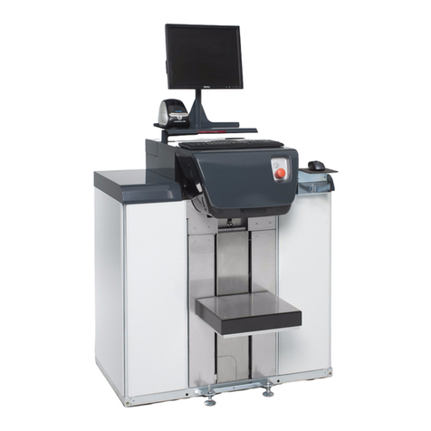
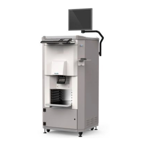
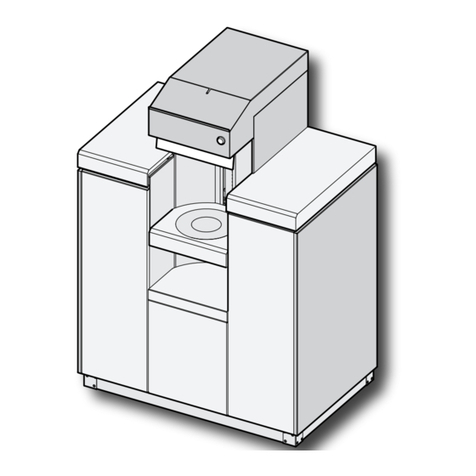
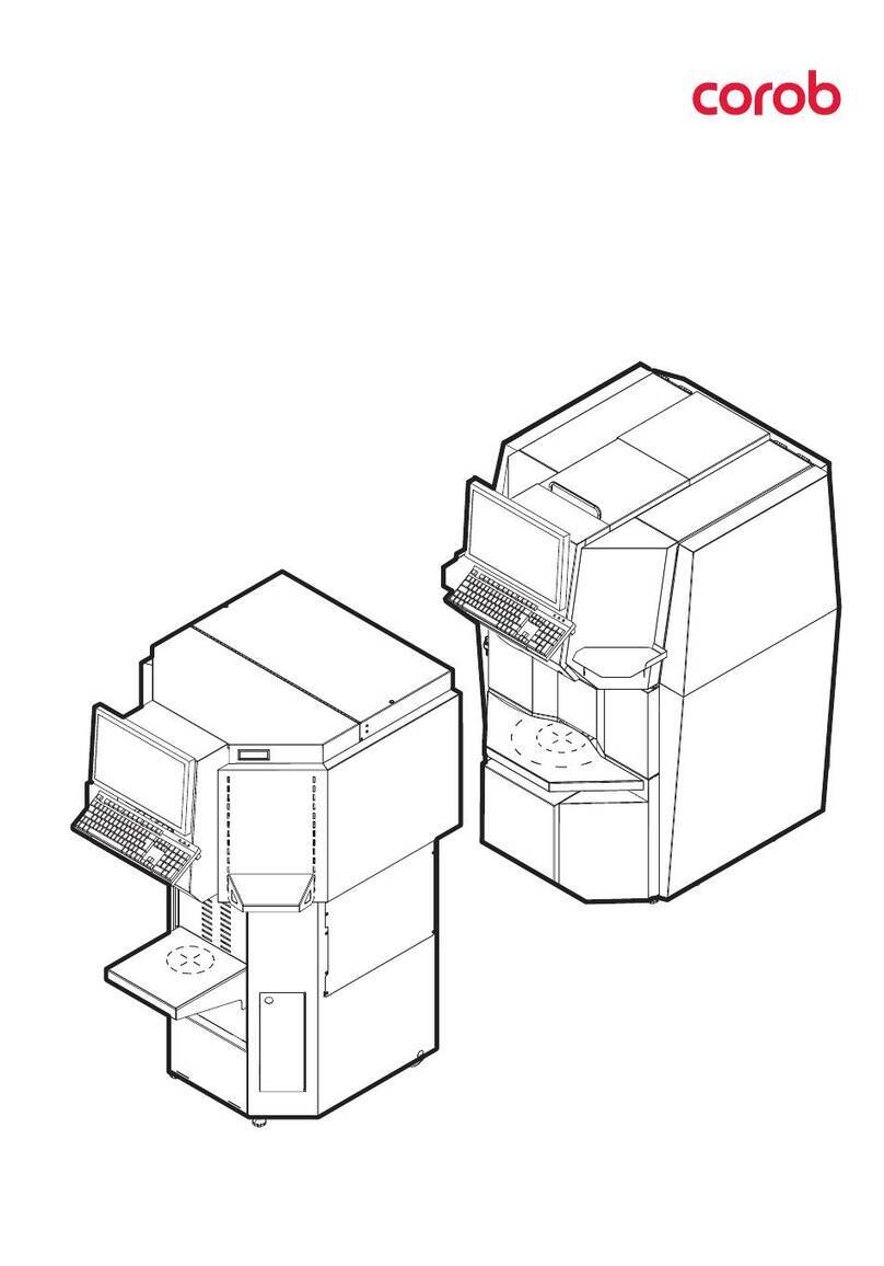
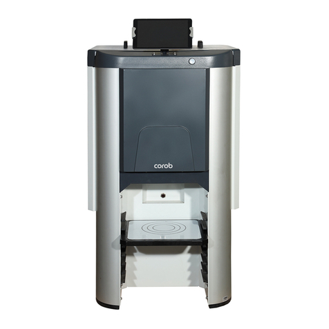
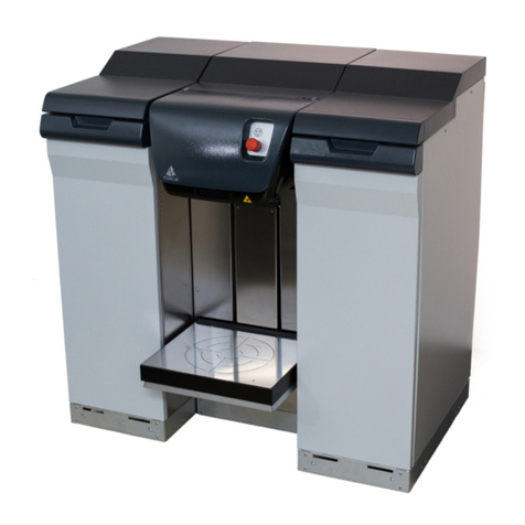
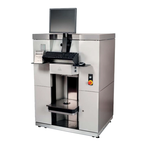
corob D300 User manual

Version 1.0 RA(2005)
COROBTM D300
Automatic dispensing machine
Service and Maintenance

CPS Color Equipment Oy
COROBTM D300
Service and Maintenance manual
Version 1/05
© COPYRIGHT 2005, CPS Color Equipment Oy
All rights reserved
Copying and editing this material in any way (e.g. saving and photographing it) is forbidden without explicit written
permission from CPS Color Equipment Oy.
All references to companies, names, dates and addresses on the display or in the examples are, unless otherwise
mentioned, entirely incidental and meant only to clarify how CPS Color Equipment Oy's products are used.
We develop our products continuously. The information in these instructions do not bind CPS Color Equipment Oy in
any way. In unclear cases we ask you to contact the manufacturer or service provider.
Additional copies of these instructions or additional technical information is available from the following address:
CPS Color Equipment Oy
Päivöläntie 5 • FIN-28400 Ulvila • FINLAND
Tel: +358 2 6777 700 • Fax: +358 2 6777 701 • E-mail: service_fi@cpscolor.com
www.cpscolor.com

- 1
TABLE OF CONTENTS
1 GENERAL.................................................................................................................... 2
1.1 COROBTM D300 parts.......................................................................................... 2
1.2 The control system of COROBTM D300 .................................................................... 4
1.3 Technical information .......................................................................................... 8
2 MACHINE INSTALLATION ........................................................................................ 10
2.1 Installation site requirements ............................................................................. 10
2.2 Installation ...................................................................................................... 10
2.3 Mounting monitor cables .................................................................................... 13
2.4 Mounting the keyboard and the mouse cable ....................................................... 14
3 MAINTENANCE INSTRUCTIONS ............................................................................... 15
3.1 Removing the front casing.................................................................................. 15
3.2 Removing the can table during service................................................................. 15
3.3 Tilting the dispensing module.............................................................................. 16
3.4 Changing the solenoid rail assembly .................................................................... 17
3.5 Adjusting the valve solenoid ............................................................................... 18
3.6 Changing the puncher blade (optional)................................................................. 19
3.7 Maintenance of the hydraulic lift unit ................................................................... 20
3.7.1 Changing the hydraulic lift unit.................................................................. 20
3.7.2 Venting.................................................................................................. 23
3.7.3 Adding oil............................................................................................... 24
3.8 Replacing a pump ............................................................................................. 25
3.8.1 Removing a pump ................................................................................... 26
3.8.2 Installing a pump .................................................................................... 27
3.9 Replacing a canister .......................................................................................... 28
3.9.1 Removing a canister from the machine....................................................... 29
3.9.2 Installing a canister ................................................................................. 30
3.10 Replacing a sensor .......................................................................................... 32
How to check the functioning of the IR sensors: ................................................... 33
3.11 Replacing the processor and the connector board ................................................ 33
3.12 Replacing a motor ........................................................................................... 34
3.12.1 The dispensing motor............................................................................. 34
3.12.2 The stirring motors ................................................................................ 37
4 SERVICE OPERATIONS ............................................................................................. 39
5 ESSENTIAL ERROR CODES........................................................................................ 40
Error code 8000: Photocell. No can on the can table. ............................................ 40
Error code 8002: OFFLINE button pressed. .......................................................... 40
Error code 8102: E7 error ................................................................................. 40
Error code 8104: Busy error. Machine is busy. ..................................................... 40
Error code 8197: CRC error on data receive. ....................................................... 41
Error code 8199: No reply from the machine. ...................................................... 41
Error code 8501: Error: Cap closed during dispensing ........................................... 41
6 ELECTRICAL DIAGRAM ............................................................................................. 42
7 KOECDRIVER............................................................................................................ 45
7.1 Tests............................................................................................................... 45
7.1.1 Serial test .............................................................................................. 45
7.1.2 Encoder and zero sensor test .................................................................... 45
7.1.3 Cup sensor test....................................................................................... 45
7.1.4 Can sensor test....................................................................................... 45
7.1.5 Stirring tests........................................................................................... 46
7.2 Configuration settings........................................................................................ 46
7.3 Purge, init and dispense commands..................................................................... 47
2 1 - General
COROBTM D300
1 GENERAL
1.1 COROBTM D300 parts
COROBTM D300 is an automatic dispensing machine available with sixteen colourant canisters. The
canister size is four or six litres. COROBTM D300 is meant for dispensing water-based colourants
and its main operational utilisation is for all kinds of shops and other institutions.
NOTE!: Optional equipment is indicated by a dashed line.
Table 1. Parts of the dispensing machine
1. Monitor 2. Keyboard
3. Water reservoir 4. Main switch
5. Hydraulic can table 6. Mouse
7. Punching device arm 8. ON/OFF switch
9. Punching blade 10. Pedals of the can
table
1
3
5
7
6
Figure 1: COROBTM D300’s parts
2
8
4
9
10

1 - General 3
Main mechanical parts
Order of the pumps and hoses
The numbering of the canisters and pumps is also marked in figure 50 on page 25.
3
1
2
4
C
Figure 2: Main assemblies:
1. Foot
2. Upper frame
3. Can table
4. Puncher
2
1
4
3
Figure 3: Parts of the upper frame:
1. Rack for canisters
2. Colorant canisters
3. Dispensing module
4. Valves
C Interface board C
Figure 4: Fixing order of the hoses and numbering of
pumps and canisters is marked in above picture.
Remember that the picture is taken from underside.

4 1 - General
COROBTM D300
The dispensing module
Table 2. Parts of the dispensing module
1.2 The control system of COROBTM D300
The COROBTM D300 is controlled by processor board, which controls COROBTM D300’s motors
through the connector board.
1. Power supply 2. Processor board
3. Connector board 4. ON/OFF switch
5. Air pump 6. Solenoid of the humidifier cap
7. Dispensing motor 8. Interface board A
9. Nozzle 10. Cable interface
Figure 5: COROBTM D300’s dispensing module is behind the front
cover.
1
2
3
4
56
7
8
10
9
PC
M
M
1
C
P
PULSE ZERO CUP
Figure 6: The control system of COROBTM D300
B
A
RS232
C
MM#1 #16
...

1 - General 5
Explanations
P = processor board
C = connector board
RS232 = Standard defining communication between a computer and the COROBTM D300
PULSE = Pulse sensor
ZERO = Zero sensor
CUP = Humidifier cap sensor
M1 = Dispensing motor
A = Interface board for valves
B = Interface board for pumps
C = Interface board for stirring motors
M = Stirring motors, 16 pieces
The sensors are connected to the connector board that transmits information to the processor
board and to the PC.
All boards that are in the COROBTM D300 are shown in figure 7. The order code for each board is
after the name of the board in table 3.
Table 3. Boards in figure 7
1. Connector board (V44752) 2. Processor board (V43786)
3. Interface board C: Stirring (V44846)
4. Interface board B: Solenoids for selecting the pumps (V44844)
5. Interface board A: Solenoids for opening the valves (V44845)
6. IR receiver board (V06271) 7. IR transmitter board (V06270)
8. Cable interface (V44971) 9. Pulse sensor (V43769)
10. Zero sensor (V43773) 11. Humidifier cap sensor
(V43676)
Figure 7: Boards of COROBTM D300

6 1 - General
COROBTM D300
The COROBTM D300 has three interface boards: A, B and C. The boards A and B are for controlling
solenoids. The solenoid board A that controls the valves is in front of the dispensing module, in the
lower part of it, see number 8 in figure 5. The other solenoid board, board B, is in the solenoid rail
assy behind the dispensing module, see figure 9. The pump or the pumps that are going to
dispense are selected with this board.
Movement of the impellers of the colorant canisters are controlled with the interface board C.
There is a stirring motor under each colorant canister. This motor rotates the impeller inside the
canister. The interface board C is on the right side of the canister rack, it’s marked with letter C in
figure 3 on page 3.
The locations of the sensor boards are marked in figure 71 on page 32. The cable interface is on
top of the can table, see number 10 in figure 5 on page 4.
Solenoids
The COROBTM D300 has 33 solenoids, two different sizes:
• sixteen smaller ones for selecting the piston of the pump. These solenoids are behind the
dispensing module. The wiring order to solenoids from the board is described in figure 10.
• sixteen bigger solenoids are for opening the valves. The solenoids are in front of the
dispensing module. The wiring order from the board to the solenoids is described in figure 11.
Figure 8: The wiring order to stirring
motors on the interface board C.
Figure 10: The wiring order on the
interface board B.
Figure 9: Interface board B is fastened to the
solenoid rail assy behind the dispensing
module.
Figure 11: The wiring order on board A,
which controls the movement of the valves.

1 - General 7
• one solenoid controls opening and closing of the humidifier cap. This solenoid is beside the air
pump in the dispensing module, number six in figure 5.
Sensors
The sensors in the COROBTM D300 are used for
• monitoring if the humidifier cap is under the nozzles or not, (CUP)
• counting the pulses of the dispensing motor (PULSE),
• monitoring when the crank passes 0 point (ZERO) and
• monitoring if a paint can is on the table or not.
The sensor of the humidifier cap is attached to the nozzle assembly. The pulse and the zero
sensors are connected to the dispensing module assembly. The can sensor is on top of the can
table.
You can also see the location of the sensors in figure 71 on page 32 and in figure 72 on page 33.
1
2
Figure 12: The dispensing module assembly
(V44517), which includes also the pulse (1) and
the zero sensor (2).

8 1 - General
COROBTM D300
1.3 Technical information
Dispensing system and technology
• Volumetric, simultaneous dispensing but only three colourants at a time.
NOTE! If the dispensing volume of one colourant is less than 0.3ml, only one colourant is
dispensed at a time.
• Piston pumps: only the piston of the pump in use is moving
Dispensing parameters
• Fluid Ounce: US (29.57ml) or metric (31.24ml)
• Smallest unit size: 1/384Fl.oz
• Accuracy: ± 1%, with shots greater than 1ml
Specifications
• Water and glycol based and non-VOC colourants
Measurements Package(with content)
Length 1040mm 1310mm
Width 745mm 950mm
Height 1465 mm 1550mm
Volume 1.1m31.9m3
Weight 174kg* 255kg
* includes PC
Electric
Voltage 100 - 240V
Power 50 / 60Hz
Fuses 2 * 10A
Technical properties
Number of canisters max 16
Volume of canister 4 or 6l
Pump type Piston pump
Dispensing Volumetric, max. 3 colorants simultaneously
Dispensing capacity, average 0.35 l /min.
Diameter of puncher (option) 50mm
Hydraulic can table: measurements of the can
max size 30l
max diameter 340mm
min. height 70mm
max height 450mm

1 - General 9
Motors
• Dispensing motor
location: in front of the machine, see figure 5 on page 4.
• Stirring motors
location: under each canister, see figure 13.
Disconnection of the motors is explained in the section “Replacing a motor” on page 34.
Figure 13: The impeller in every canister has an
own stirring motor.

10 2 - Machine installation
COROBTM D300
2 MACHINE INSTALLATION
The COROBTM D300 is delivered packed in a wooden crate that, in addition to the dispensing
machine, contains an equipment package and all the ordered optional parts.
2.1 Installation site requirements
To ensure ease of use, take into account the following details when installing the machine:
1. The machine should be operated at room temperature, in a room with no harmful humidity or
drafts and adequate air conditioning.
2. The machine must be placed away from direct sunlight.
3. The operating site must have adequate lighting.
4. Place the mains plug in such a place that it can be unplugged without moving the machine.
5. Check that the floor is not slippery or uneven.
6. Electrical interface:
100 - 240 V,
50/60 Hz / F 10 A
Earthed wall socket
7. Machine dimensions, see “Technical information” on page 8.
2.2 Installation
NOTE!: An instruction for removing the COROBTM D300 from the package is attached to the
machine!
Installation step by step:
1. Carefully remove the COROBTM D300 from the transport package:
- Remove the packing material around the machine
- Remove the equipment package and other possible accompanying equipment like
computer and monitor from the top of the foot.
- Remove the steel straps and planks that are used to attach the COROBTM D300 on the
pallet.
- Place the side of the transport package as a ramp: the other edge of the cover below the
foot of the COROBTM D300 and the other edge on the floor.
- Slide the COROBTM D300 along the ramp to the floor.
NOTE!: At least two persons must work together to remove the machine from the package.
NOTE!: The COROBTM D300 moves best backwards.
WARNING! Only a service representative authorised by the supplier may install the
machine.
CAUTION / IMPORTANT If the dispensing machine is brought in from a cold temper-
ature, wait one day before using the machine. The temperature difference may
condense moisture on the machine's components, which could damage the
machine's electronics when the power is switched on.

2 - Machine installation 11
2. Check that the dispensing machine and accompanying equipment have not been damaged
during transport.
3. Check that all the ordered items have been delivered. It’s also good to check that the accom-
panying accessory kit contains everything it should.
NOTE!: If the machine is damaged or the content does not correspond to the order, contact the
service centre or seller.
4. Place the COROBTM D300 to it’s operating site considering the requirements mentioned on
previous page.
5. Adjust the two adjustable feet below the front part of the foot to ensure that the machine
stands steadily.
6. Place the PC (optional) behind the can table on foot of the COROBTM D300 and the monitor on
the monitor rack, see figure 1 on page 2. Connect the necessary cables to the mains
connecting plate that is under the machine, see figure 14.
The COROBTM D300 has two different power switches:
The machine power switch is beside the sockets in the mains connecting plate. This switch
cuts off all power from the machine and other equipment.
The main switch is on the left side of the can table unit, see number 4 in figure 1 on page 2.
The main switch cuts off the power from the COROBTM D300, but leaves the power on to the
mains connecting plate. This means that equipment that got their power through the COROBTM
D300’s connecting plate, like the air pump, monitor or computer, are not switched off.
7. Install the cables of monitor, keyboard and mouse, if necessary. The instruction is in the
manual folder which is delivered in the accessory kit.
8. Fill the water reservoir in front of the machine with cold water.
NOTE! Use only water in the reservoir!
9. Also attach the mains cable to the connector plate, see figure 14.
10. Switch on the CPU and monitor.
11. Fill the colorant canisters, if the machine is not delivered with the colorants inside.
NOTE!: Add colorant so that the canister is at least half full.
12. Lift up the draft bar that is in front of the pump few times to fill up the hose from nozzle to the
pump.
NOTE!: It is recommended that you calibrate the COROBTM D300 on the following day after filling
up the canisters.
13. Switch on the dispensing machine the COROBTM D300.
Serial line
cable
Mains
cable
Machine
power
switch
Guide
Figure 14: The sockets for COROBTM D300’s
cables are in a connector plate under the
machine beside the left guide.

12 2 - Machine installation
COROBTM D300
14. Adjust the colorant level alarm for the correct amount, 0.5 - 1l, by activating the colorant
control of the machine driver software.
=> The machine reduces the colorant amounts used in dispensing and informs if there is not
enough some colorant.
This way you can add colorant during dispensing and the dispensing continues normally after
that.
15. Check that the pistons of the pumps are not in their lowest position.
16. Run Purge (Sequential) -test and check that the valves, solenoids and pumps are working, see
the section “Purge, init and dispense commands” on page 47.
17. Remove the air from the hoses, pumps and nozzles by dispensing 500ml of colorant from each
canister. Do it either with Free dispense or Manual dispense programs:
- Start the program
- Change the unit to ml, if necessary.
- Dispense 500ml of each colorant to a clean container.
- Pour the dispensed amount back to the canister.
- Close the program by pressing the cross at the top right corner of the window.
18. Check that the puncher (optional) works properly.
19. Check that the humidifier cap works correctly.
20. Check that the space between the humidifier cap and the nozzles is 0.5 - 1mm.
21. Fill in the Installation report and Warranty registration form and send it to CPS Color
Equipment Oy.
NOTE!: The warranty becomes valid after installation. However, this will never exceed 14 months
from the delivery.
Figure 15: The piston of the pump must be lifted up a little, when the
pumps are in the machine.
0.5 - 1mm
Figure 16: The humidifier cap is under
the nozzles.

2 - Machine installation 13
2.3 Mounting monitor cables
Procedure
1. Lift up the monitor arm and corner frame, figure 17.
2. Pass two protective hoses, length 450 mm, around the monitor cables as shown in figure 18.
3. Pass the cables inside the monitor arm.
4. Push the arm inside the beam.
5. Pass the cables over the beam behind the side plate.
6. Put the corner frame back in place.
Figure 17: The monitor arm and corner
frame are lifted up. Figure 18: Two protective hoses, violet ones,
should be placed like this.
Figure 19: Both the arm and corner frame
are in place. Figure 20: The cables run inside the left side
plate.

14 2 - Machine installation
COROBTM D300
2.4 Mounting the keyboard and the mouse cable
Figure 21: Stick 4 pairs of stickers in the
bottom of the keyboard. Figure 22: Remove the front casing and
panel. Attach 5 adhesive cable tie mounts
(circled in the picture) to the machine.
Figure 23: Fasten both the mouse cable and
the keyboard cable to the mounts with cable
ties.
Figure 24: Put the front casing and panel
back in place. Fasten the keyboard with
stickers on top of the casing.

3 - Maintenance instructions 15
3 MAINTENANCE INSTRUCTIONS
3.1 Removing the front casing
The COROBTM D300’s dispensing module is protected with a front casing. You can remove this
casing only for service.
Tools required:
• 4mm Allen key
Procedure:
1. Turn the monitor stand (optional) aside away from the top
of the machine.
2. Open the cover which is over the colorant canisters: press
down the front edge of the cover and push backwards.
3. Remove the keyboard and mouse from the top of the front
casing.
4. Loosen the locking nut that fastens the puncher handle
(optional) to the crank and remove the handle, see figure
25.
5. Remove the water reservoir.
6. Open the two screws which are behind the reservoir.
7. Remove the front casing by pulling it away from the machine.
3.2 Removing the can table during service
If you have to tilt the dispensing module forward for maintenance or you have to access parts
under the machine such as the pumps, stirring motors, canisters or hoses, the can table in front of
the machine has to be removed.
Tools required:
• 8mm Allen key
• 8 and 10mm set wrench
Procedure:
1. Unplug the mains from the outlet.
2. Remove the front casing according to instructions given above.
3. Remove the humidifier cap, so it will not get broke while moving the can table.
4. If the COROBTM D300 has punching, remove the striking rod behind the puncher as follows:
- Put the puncher handle back in place and press the handle down.
- Open the locking nut of striking rod, see figure 26.
- Screw the rod from out of place.
WARNING! Punching blade may cause personal injury.
5. Detach the cable from the cable interface, see figure 27.
WARNING! Before service, repairs and cleaning, unplug the mains from the outlet.
Figure 25: The puncher
handle is attached to the
crank with one locking nut.

16 3 - Maintenance instructions
COROBTM D300
6. Open the two screws which are in lower-front-part of the can table. These screws fasten the
can table to the foot, see figure 28.
7. Lift up the fasteners which are on top of the can table and detach the upper part of the can
table. You can see the fastener on the left in figure 29 and the right one in figure 27.
8. Place the puncher handle (optional) back in place and lower the puncher blade. Now it is
easier to remove the table.
9. Pull the can table away from the COROBTM D300.
10. Attach the can table back in place in opposite order.
NOTE!: Make sure that the removed can table stands.
3.3 Tilting the dispensing module
Tools required:
• 2.5 mm Allen key
Procedure:
1. Switch off the COROBTM D300 and unplug the mains cable from the outlet.
2. Remove front casing, see instructions on page 15.
3. Remove the hydraulic can table, see “3.2 Removing the can table during service”.
4. Remove the top screw on both sides of the dispensing module, see figure 30.
Fastener
Figure 27: Detach the cable from the cable
interface.
Figure 26: The striking rod (1) is locked with a
nut (2) and they are behind the puncher blade.
Figure 29: The fastener on the left.Figure 28: The can table is attached with
two screws to the foot of the COROBTM
D300.

3 - Maintenance instructions 17
5. Lift both catches (figure 30) on the sides of the dispensing module away from the groove in
the front plate of the rack for canisters.
=> the top of the dispensing module tilts forward, like in figure 31.
3.4 Changing the solenoid rail assembly
Tools required:
• 3 mm Allen key
Procedure
1. Switch off the COROBTM D300 and unplug the mains cable from the outlet.
2. Remove front casing, see instructions on page 15.
3. Remove the hydraulic can table, see “3.2 Removing the can table during service”.
4. Tilt the dispensing module forward according to “3.3 Tilting the dispensing module” .
5. Disconnect the flat cable from the interface board B, see figure 9 on page 6.
6. Open the Allen screws on both ends of the solenoid rail, see figure 32.
7. Remove the solenoid rail and install a new one.
8. Check that the horizontal part of the solenoid rail is on same level with the top of the hinge on
the side of the dispensing module, see figure 33.
If the rail is too low the plastic hooks do not reach the piston rods when the solenoid is
activated.
9. Adjust the rail by bending it, if necessary, so that all the solenoids are aligned.
NOTE!: The solenoids must be in straight line in order to hit the plastic hooks!
10. Fasten the rail with screw in place.
11. Assemble the COROBTM D300 in opposite order.
Catch
Figure 31: The dispensing module is
tilting forward.
Figure 30: The catch that locks the
dispensing module is fastened with one
screw.

18 3 - Maintenance instructions
COROBTM D300
3.5 Adjusting the valve solenoid
The fixing screws of valve solenoid are fastened somewhere in the middle of the fixing slots. The
lowest position is not probably the correct one for the solenoid because there is a risk that in some
cases the valve might leak back to the canister during dispensing.
Tools required:
• Cross head screwdriver
Procedure:
1. Loose the solenoid fixing screws (marked with arrow to figure 35) so that the solenoid drops
to the lowest position.
2. Place a small tool under the plunger and push the plunger upwards until the draft bar touches
the outlet of the pump, see figure 35. Also the solenoid coil moves upwards.
3. Tighten the solenoid to this location with screws.
Hook Hook
Hinge
Figure 32: The solenoid rail is fastened on
both ends with a screw to the dispensing
module.
Figure 33: The solenoids have to be in
straight line in the solenoid rail.
Figure 34: Place a tool under the plunger. Figure 35: Push the plunger upwards until
the draft bar touches the outlet of the pump
(white arrow).
Table of contents
Other corob Dispenser manuals

corob
corob Tatocolor User manual

corob
corob FLEX 200 User manual

corob
corob D600 extra User manual

corob
corob Flex 900 User manual

corob
corob EVOFLX-LW User manual

corob
corob D800 HD User manual

corob
corob D600 extra User manual

corob
corob FIRST 70 User manual

corob
corob FLEX 500 User manual

corob
corob PROsample 200 User manual
Popular Dispenser manuals by other brands

Compac
Compac Laser AdBlue LA 30S Installation and setup instructions

COFRIMELL
COFRIMELL mini CAPRI Operating handbook

Rieber
Rieber RR Series user guide

Hilti
Hilti HDE 500-A22 operating instructions

Georgia Pacific
Georgia Pacific Pacific Blue Ultra 59589 Mounting instructions

Reddot
Reddot AUTOMATED HANDS-FREE ROLL TOWEL DISPENSER Mounting instructions