manuals.online logo
Brands
  1. Home
  2. •
  3. Brands
  4. •
  5. DUCATI Performance
  6. •
  7. Motorcycle Accessories
  8. •
  9. DUCATI Performance 97380931B User manual

DUCATI Performance 97380931B User manual

Symbols
The symbols used in this manual are aimed at making reading di-
rect and easy. The symbols are used either to draw the reader's


to these symbols as they are used to remind of technical principles
or safety measures which will not be repeated extensively. They
must therefore be considered as "reminders". Check with this page
in case of doubt about their meaning.

Failure to comply with these instructions may put you at risk and
lead to severe injury or death.

It indicates the possibility of damaging the motorcycle and/or its
components if the instructions are not followed.

It supplies useful information about the operation in progress.
References
 1
) represent the accessory to be installed and any assembly compo-
nents supplied with the kit.
 A) represent the original
components present on the motorcycle.
-
tion of travel (forward riding position).


The operations listed in the following pages must be carried out by
a specialised technician or by a Ducati authorised service centre.




The Workshop Manual of your motorcycle model is the documen-
tation required to assemble the Kit.





highway motor vehicle can expose you to chemicals including en-
gine exhaust, carbon monoxide, phthalates, and lead, which are

or other reproductive harm. To minimize exposure, avoid breath-
ing exhaust, do not idle the engine except as necessary, service
your vehicle in a well-ventilated area and wear gloves or wash your
hands frequently when servicing your vehicle. For more informa-
tion go to www.P65Warnings.ca.gov/passenger-vehicle.
 - 97380931B


       

simboli, in quanto la loro funzione è quella di non dovere ripete-

  
ogni volta che sorgeranno dubbi sul loro significato.

-


-

Note
Fornisce utili informazioni sull’operazione in corso.
Riferimenti
 1)
rappresentano l’accessorio da installare e gli eventuali componenti
di montaggio forniti a kit.
      A) rappresentano i
componenti originali presenti sul motoveicolo.

del motociclo.


-
-
cati.

-

Note
Documentazione necessaria per eseguire il montaggio del Kit è il

Note

consultare la tavola ricambi allegata.
 - 97380931B
1
ISTR - 1052 / 00
ISTR 1052 / 00

2
12
1413
7
7
6 2 8
10
6 8
4 1
9
5
5
11
3
3



-
ranged as a track.


paesi in cui le leggi che regolano la circolazione stradale lo consen-


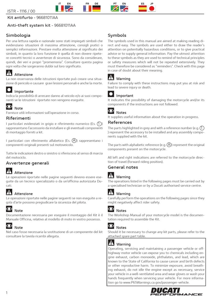
Pos. Denominazione Name
1 
2 
3 
4Piastrino Plate
5 Dado cieco M6 Cap nut M6
6Vite TBEIF M6x12 TBEIF screw M6x12
7Vite TBEIF M6x18 TBEIF screw M6x18
8Vite TCEIR M6x16 TCEIR screw M6x16
9Parafango posteriore inferiore Rear lower mudguard
10 Vite TBEIF M6x14 TBEIF screw M6x14
11 Vite TBEI M4x8 TBEI screw M4x8
12  Bracket
13 Tappo Plug
14 Tappo Plug
ISTR 1052 / 00
3


-
wise and simultaneously press downward in the area of the catch
to release the pin. Pull the seat (B) backwards to release it from the
front retainers.


Aprire il coperchio (A1) e introdurre la chiave nella serratura (A).
Ruotare la chiave in senso orario e contemporaneamente premere

del piolo. Sfilare la sella (B) dai fermi anteriori tirandola all’indietro.
4
ISTR 1052 / 00
4
B
A1
A

-


to cool down.




(wood, leaves etc.).

Working on the lower side of the rear mudguard, loosen no.2

bracket (C).

 

-





-

ecc.).



silenziatori (C).
ISTR 1052 / 00
5
C
C1
C2

      

bracket (D6) by releasing no.2 stud bolts (D7) from no.2 vibration
dampers (D8). Position tail light (D) on the electrical components

damage it. Make sure that no.2 spacers with collar (D4) remain fit-
ted on no.2 vibration dampers (D3). Loosen no.3 screws (D5) and
         
bracket (E1).


 

dai n.2 gommini antivibranti (D8). Posizionare il fanale posteriore
       
      
che i n.2 distanziali con collare (D4) rimangano montati sui n.2
gommini antivibranti (D3). Svitare le n.3 viti (D5) e rimuovere la
       

6
ISTR 1052 / 00
6
E1
D5
D
D3
D4
D1
D2
D1
D2
D3
D4
D6
F1
D5
D
D7
D8D6
D7

   -

(F2) and (F3) of main wiring. Loosen no.2 upper screws (G1) and
no.2 lower screws (G2) securing rear mudguard assembly (G). Re-
move the rear mudguard assembly (G) from the motorcycle, paying




(F2) ed (F3) del cablaggio principale. Svitare le n.2 viti superiori
(G1) e le n.2 viti inferiori (G2) di fissaggio del gruppo parafango
posteriore (G). Rimuovere il gruppo parafango posteriore (G) dal

degli indicatori di direzione.
ISTR 1052 / 00
7
F2
G1
G
P1
G2 F3
G2
N1

Loosen no.2 screws (H1) with no.2 washers (H2) and remove the
upper rear mudguard (H) from the lower rear mudguard assembly


wirings. Loosen and keep no.4 screws (G3). Collect no.4 clips (G4)
from the plate (G5) as shown in the box (X).


posteriore superiore (H) dal gruppo parafango posteriore inferiore
(G). Rimuovere l’indicatore di direzione destro (P) e l’indicatore di
       

recuperare le n.4 viti (G3). Recuperare le n.4 clip (G4) dalla piastra
(G5) come mostrato nel riquadro (X).
8
ISTR 1052 / 00
8
G
G3
G3
G3
G4
G4 X
H2
H2
H
H1
H1
N
P
G5


-
bly, footpeg assembly and LH levers are not shown.

remove chain guard (l).
          
screws (L1) that secure no.3 cable rings (L2) to swinging arm (M),
releasing the number plate light extension (O4).

Note
Per comprendere al meglio le procedure di smontaggio, non viene
rappresentato il gruppo stampella laterale e il gruppo pedana e
levismi sinisto.
Operando sul lato sinistro del motoveicolo, svitare le n.2 viti (I1) e
rimuovere il paracatena (I).
Operando sul piano inferiore del forcellone (M), svitare le n. 3 viti
(L1) che fissano i n. 3 passacavi (L2) al forcellone (M), svincolando la
prolunga luce targa (O4).
ISTR 1052 / 00
9
L1
O4
L2
M
ISTR 1052 / 00
10
O1
O4
P1M
O3 O5
O2
O4
P
Working on motorcycle RH side, remove self-locking tie (O1).


assembly and number plate holder assembly are shown.
Disconnect the number plate light cable (O2) from the number
plate light extension (O4). Loosen screw (O3) and remove cable
ring (O5) to completely free number plate light cable (O2).
Loosen no.2 screws (P1) fastening number plate holder assembly


strappo (O1).
Note
Per comprendere al meglio le procedure di smontaggio, vengono

Scollegare il cavo luce targa (O2) dalla della prolunga luce targa
(O4). Svitare la vite (O3) e rimuovere il passacavo (O5) per liberare
completamente il cavo luce targa (O2).

al forcellone (M).
ISTR 1052 / 00
11
Working on the LH side of the motorcycle, loosen and remove
screw (P2) complete with washer (P4) and screw (P3) complete
with washer (P5). Remove number plate holder assembly (P) from
swinging arm (M).
Close the holes on the swinging arm with plugs (13) and (14) sup-
plied with the kit.
Operando sul lato sinistro del motoveicolo, svitare e rimuovere la
vite (P2) completa di rondella (P4) e la vite (P3) completa di ron-

Chiudere i fori presenti sul forcellone con i tappi (13) e (14) in dota-
zione nel kit.
12
ISTR 1052 / 00
12
P2
P4
P3
13
14
P
M
P5
Loosen no.3 screws (P6) and remove no.3 cable retainers (P7) fas-
tening number plate light wiring (O2). Loosen no.2 lower screws
(P8), while holding the corresponding nuts (P9) on the opposite
side, and remove plate (P10) complete with cat's eye (P11). Loosen
the remaining no.2 screws (P8), while holding no.2 nuts (P9) on
the opposite side, and remove number plate (Q). Remove the no.4
screws (P8) and no.4 nuts (P9).
Loosen no.2 nuts (P12) and remove the cat's eye (P11), complete
with washers (P13) from plate (P10). Keep no.2 nuts (P12), cat's eye
(P11) and no.2 washers (P13).
Loosen no.3 screws (P14) and remove number plate holder plate
(P15), complete with number plate holder light (O) from number
plate holder assembly (P).

When removing number plate holder plate (P15), take care not to
damage number plate holder light cable (O2).
Svitare le n.3 viti (P6) e rimuovere i n.3 ferma cavo (P7) di fissaggio
cablaggio luce targa (O2). Svitare le n.2 viti inferiori (P8), mante-
-

(P8), mantenendo dal lato opposto i n.2 dadi (P9) e smontare la
targa (Q). Conservare le n.4 viti (P8) e i n.4 dadi (P9).

rondelle (P13) dalla piastra (P10). Conservare i n.2 dadi (P12), il ca-

-




ISTR 1052 / 00
13
P
O2
P8 Q
P14
O2
P
P15
O
P9
P9
P9 P7
P6
P12
P7
P10P20P11
P13
P13


-
ditions. Adopt all necessary precautions to avoid damaging any


Fit no.4 original clips (G4) on number plate holder subframe (1),
aiming them as shown in the figure. Position number plate holder

screws (8). On the opposite side, tighten no.4 cap nuts (5) on the
thread of no.4 screws (8). Tighten no.4 screws (8) to the specified
torque, while holding no.4 cap nuts (5) from the opposite side.
         

torque.


        


operare.

-
     -


(8). Serrare le n.4 viti (8) alla coppia indicata, mantenendo dal lato


(6) alla coppia indicata.
14
ISTR 1052 / 00
14
10 Nm ± 10%10 Nm ± 10%
6 2 8
6 8
5
5
3
1
G4
G4


original number plate holder plate (P15) on number plate holder
         
plate light wiring (O2) is in the correct position as shown in the
box (X), and that it is not squeezed. Tighten no.3 screws (10) to
the specified torque. Pre-assemble original rear cat's eye (P11)


nuts (P12). Tighten no.2 nuts (P12) to the specified torque. Position
    
original screws (P8) in the upper holes and screw no.2 nuts (P9)
from the internal side. Position the just pre-assembled rear cat's
eye assembly on the lower holes of the number plate holder plate
      
screw no.2 nuts (P9) from the internal side. Tighten no.4 screws
(P8) to the specified torque while holding no.4 nuts (P9) on the
opposite side.

Introdurre il cablaggio luce targa (C1) all'interno dell'asolatura (3A).
-
tatarga (3) e impuntare le n.3 viti (10), verificando che il cablaggio
-
quadro (X) e non risulti schiacciato. Serrare le n.3 viti (10) alla cop-
       
           
-
nali (P12). Serrare i n.2 dadi (P12) alla coppia indicata. Posizionare la

(P8) sui fori superiori e dal lato interno avvitare i n.2 dadi (P9). Posi-


n.2 viti (P8) e dal lato interno avvitare i n.2 dadi (P9). Serrare le n.4
viti (P8) alla coppia indicata, mantenendo dal lato opposto i n.4
dadi (P9).
ISTR 1052 / 00
15
P8
10
Q
P15
P9
3A
O2
12P9
P9
P12
P12
3
5 Nm ± 10%
0,7 Nm ± 10%
0,7 Nm ± 10%
10 Nm ± 10%
X
P13
P13
P11

Position the number plate light wiring branch (O2) on number plate
holder extension (2), as shown in the figure. Fit plate (4) on number
-
ber plate light wiring (O2) between number plate holder extension
(2) and plate (4). Apply a thin layer of Loctite 222 on the thread of

torque.

Posizionare il ramo cablaggio luce targa (O2) sulla prolunga por-
tatarga (2), come mostrato in figura. Montare il piastrino (4) sulla



delle n.2 viti (11). Impuntare e serrare le n.2 viti (11) alla coppia in-
dicata.
16
ISTR 1052 / 00
16
2
O2
11
4
2 Nm ± 10%

    
into their seats on the lower rear mudguard (9), as shown in the
figure.
Position the lower rear mudguard (9) underneath the number plate
          -
spondence of the no.4 clips previously installed on the subframe
(1). Tighten no.4 screws (G3) to the specified torque.

Rimontare l' indicatore di direzione destro (P) e l'indicatore di

parafango posteriore inferiore (9), come mostrato in figura.
         
         
corrispondenza delle n.4 clip precedentemente montate sul

ISTR 1052 / 00
17
9
P
1
N
G3
G3
5 Nm ± 10%
5 Nm ± 10%
Position the number plate holder subframe assembly (1) by rout-
ing right turn indicator wiring (P1) and number plate light wiring

through the opening (E3). Fasten number plate holder subframe
          
without tightening, no.2 original screws (G1).
        
cablaggio indicatore di direzione destro (P1) e il cablaggio luce targa



serrare, le n.2 viti originali (G1).
18
ISTR 1052 / 00
18
G1
1
P1
E
E2
E3
N1
O2



screws (G2) and no.2 screws (G1) to the specified torque.
Posizionare il parafango posteriore superiore (H) ed impuntare le

delle n.2 viti originali (H1). Impèuntare le n.2 viti (H1). Serrare alla
coppia indicata le n.2 viti (H1), le n.2 viti (G2) e le n.2 viti (G1).
ISTR 1052 / 00
19
23 Nm ± 10%
G1
23 Nm ± 10% G2
5 Nm ± 10% H1
H2
H
H1
G2
5 Nm ± 10%
H2
H1
ISTR 1052 / 00
20
D
O4
D7
D8
D6
D7
E1
D5
D
D3
D4
D1
D2
D1
D2
D3
D4
D6
D5
5 Nm ± 10% 5 Nm ± 10%
10 Nm ± 10% 10 Nm ± 10%
D6

Other DUCATI Performance Motorcycle Accessories manuals

DUCATI Performance 96780761B User manual

DUCATI Performance

DUCATI Performance 96780761B User manual

DUCATI Performance 96981321AA User manual

DUCATI Performance

DUCATI Performance 96981321AA User manual

DUCATI Performance 96780655A User manual

DUCATI Performance

DUCATI Performance 96780655A User manual

DUCATI Performance 97180791AA User manual

DUCATI Performance

DUCATI Performance 97180791AA User manual

DUCATI Performance 96680702A User manual

DUCATI Performance

DUCATI Performance 96680702A User manual

DUCATI Performance 96880921AA User manual

DUCATI Performance

DUCATI Performance 96880921AA User manual

DUCATI Performance Multistrada 1200 User manual

DUCATI Performance

DUCATI Performance Multistrada 1200 User manual

DUCATI Performance 97480211AA User manual

DUCATI Performance

DUCATI Performance 97480211AA User manual

DUCATI Performance 96780861C User manual

DUCATI Performance

DUCATI Performance 96780861C User manual

DUCATI Performance 96781171B User manual

DUCATI Performance

DUCATI Performance 96781171B User manual

DUCATI Performance 96981261AA User manual

DUCATI Performance

DUCATI Performance 96981261AA User manual

DUCATI Performance 96781491AA User manual

DUCATI Performance

DUCATI Performance 96781491AA User manual

DUCATI Performance 97480161A User manual

DUCATI Performance

DUCATI Performance 97480161A User manual

DUCATI Performance 96981461AA User manual

DUCATI Performance

DUCATI Performance 96981461AA User manual

DUCATI Performance 96781401A User manual

DUCATI Performance

DUCATI Performance 96781401A User manual

DUCATI Performance 97380182A User manual

DUCATI Performance

DUCATI Performance 97380182A User manual

DUCATI Performance 96681144AA User manual

DUCATI Performance

DUCATI Performance 96681144AA User manual

DUCATI Performance ISTR-1083/01 User manual

DUCATI Performance

DUCATI Performance ISTR-1083/01 User manual

DUCATI Performance 97180821AA User manual

DUCATI Performance

DUCATI Performance 97180821AA User manual

DUCATI Performance 96880541AA User manual

DUCATI Performance

DUCATI Performance 96880541AA User manual

DUCATI Performance 96781310B User manual

DUCATI Performance

DUCATI Performance 96781310B User manual

DUCATI Performance 96780551A User manual

DUCATI Performance

DUCATI Performance 96780551A User manual

DUCATI Performance 96681011AA User manual

DUCATI Performance

DUCATI Performance 96681011AA User manual

DUCATI Performance 96780231C User manual

DUCATI Performance

DUCATI Performance 96780231C User manual

Popular Motorcycle Accessories manuals by other brands

Scottoiler eSystem installation guide

Scottoiler

Scottoiler eSystem installation guide

KTM 79002923000 Information

KTM

KTM 79002923000 Information

Dynafit DNA User instructions

Dynafit

Dynafit DNA User instructions

MOTO GUZZI CM228502 Instructions for assembling

MOTO GUZZI

MOTO GUZZI CM228502 Instructions for assembling

Custom Dynamics Road Glide CD-RG-TS-15-B installation instructions

Custom Dynamics

Custom Dynamics Road Glide CD-RG-TS-15-B installation instructions

Indian Motorcycle 2879586 manual

Indian Motorcycle

Indian Motorcycle 2879586 manual

hepco & becker 6307558 00 01 manual

hepco & becker

hepco & becker 6307558 00 01 manual

hepco & becker 504980 00 05 quick guide

hepco & becker

hepco & becker 504980 00 05 quick guide

Bullard LTX Series user manual

Bullard

Bullard LTX Series user manual

B-PWR PAFB-X Instruction guide

B-PWR

B-PWR PAFB-X Instruction guide

Nolan N70-2 GT Safety and instructions for use

Nolan

Nolan N70-2 GT Safety and instructions for use

Abisal Nils Extreme MTW03 user manual

Abisal

Abisal Nils Extreme MTW03 user manual

hepco & becker 42139521 00 01 quick start guide

hepco & becker

hepco & becker 42139521 00 01 quick start guide

Airoh HELMET AVIATOR III instructions

Airoh

Airoh HELMET AVIATOR III instructions

CYCLOPS Explorer quick start guide

CYCLOPS

CYCLOPS Explorer quick start guide

Dynojet POWER COMMANDER FC installation instructions

Dynojet

Dynojet POWER COMMANDER FC installation instructions

PVP Communications Motor-One user manual

PVP Communications

PVP Communications Motor-One user manual

Cobra FLHC 2018 instruction manual

Cobra

Cobra FLHC 2018 instruction manual

manuals.online logo
manuals.online logoBrands
  • About & Mission
  • Contact us
  • Privacy Policy
  • Terms and Conditions

Copyright 2025 Manuals.Online. All Rights Reserved.