manuals.online logo
Brands
  1. Home
  2. •
  3. Brands
  4. •
  5. Dungs
  6. •
  7. Controllers
  8. •
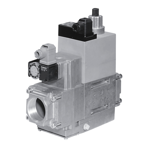
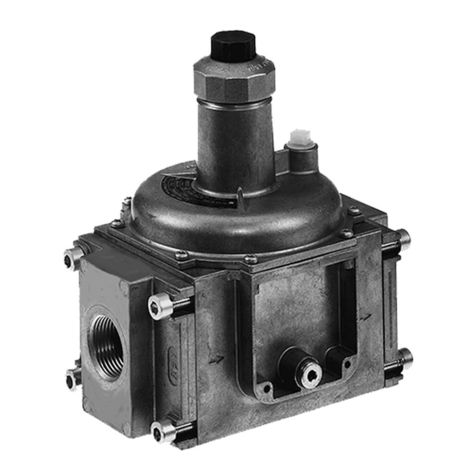
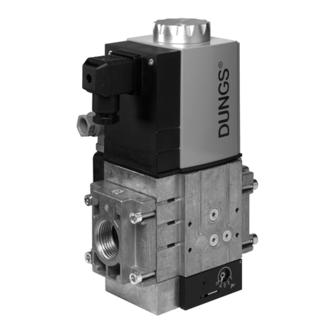
  9. Dungs GasMultiBloc MB-VEF B01 Service manual

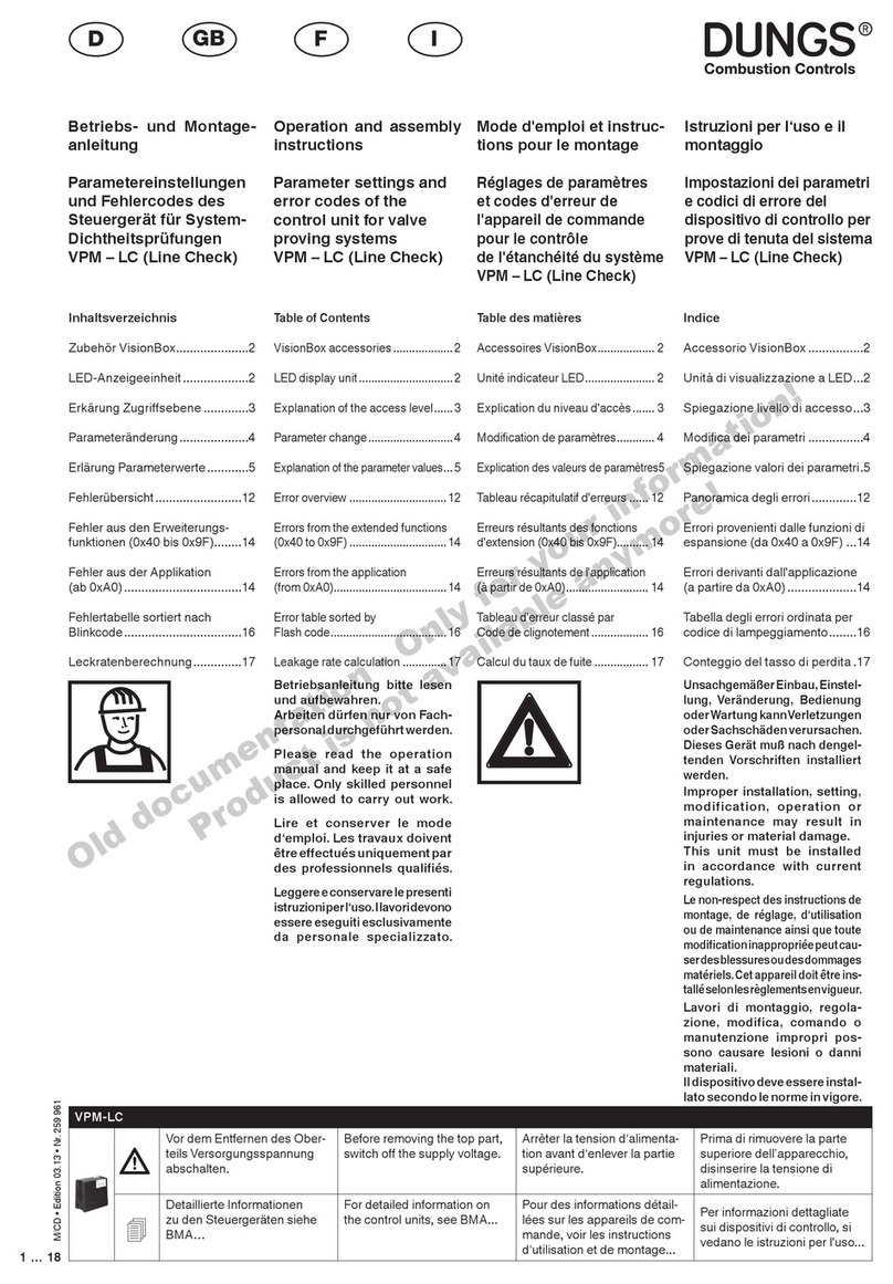
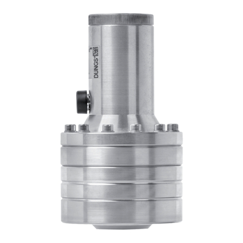
Dungs GasMultiBloc MB-VEF B01 Service manual

Other manuals for GasMultiBloc MB-VEF B01

1

This manual suits for next models

2

Other Dungs Controllers manuals

Dungs GasMultiBloc MB-ZRD B07 Series Service manual

Dungs

Dungs GasMultiBloc MB-ZRD B07 Series Service manual

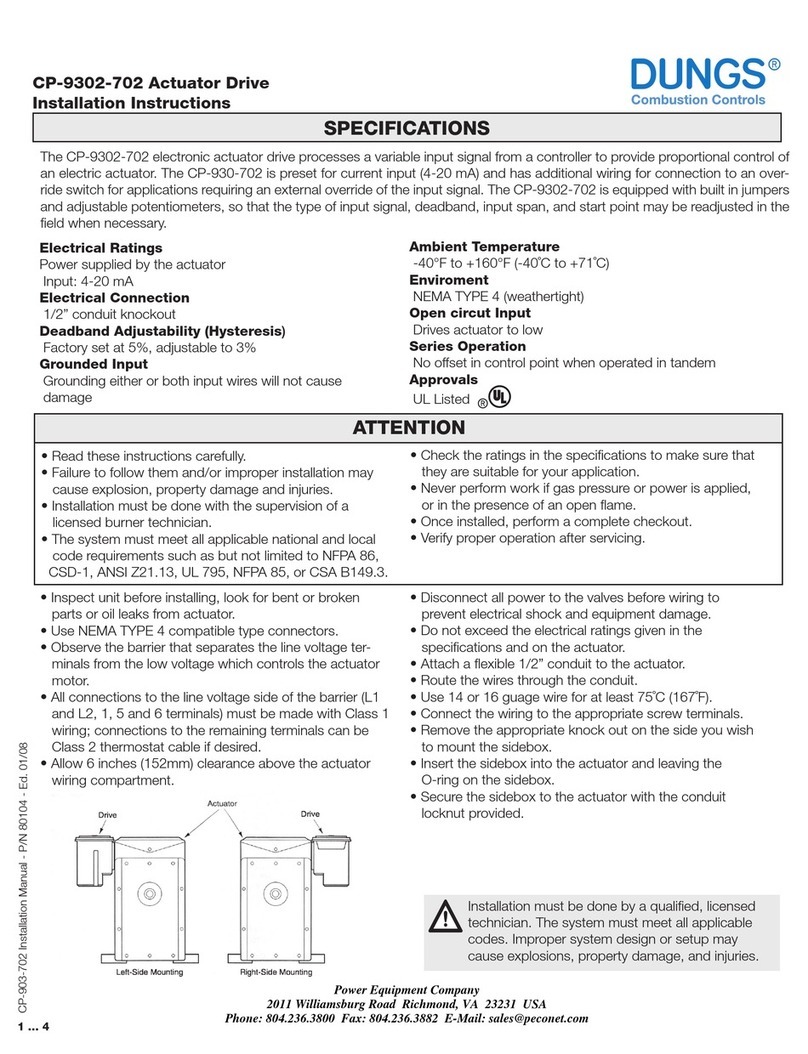
Dungs CP -9302-702 User manual

Dungs

Dungs CP -9302-702 User manual

Dungs MultiBloc MBC-SE Series Service manual

Dungs

Dungs MultiBloc MBC-SE Series Service manual

Dungs GasMultiBloc MB-D B01 Series User manual

Dungs

Dungs GasMultiBloc MB-D B01 Series User manual

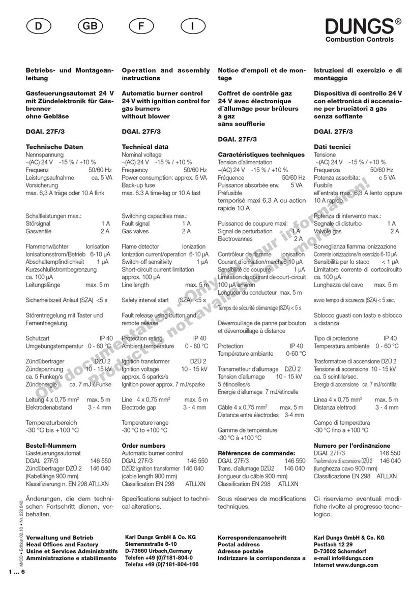
Dungs DGAI. 27F/3 Service manual

Dungs

Dungs DGAI. 27F/3 Service manual

Dungs FRM 100025 ND User manual

Dungs

Dungs FRM 100025 ND User manual

Dungs EMP-5 User manual

Dungs

Dungs EMP-5 User manual

Dungs FRM-NOC User manual

Dungs

Dungs FRM-NOC User manual

Dungs GasMultiBloc MB-D 055 D01 Service manual

Dungs

Dungs GasMultiBloc MB-D 055 D01 Service manual

Dungs FRI 7/6 Series User manual

Dungs

Dungs FRI 7/6 Series User manual

Dungs FRM 100065 User manual

Dungs

Dungs FRM 100065 User manual

Dungs FRM 100065 User manual

Dungs

Dungs FRM 100065 User manual

Dungs DGAU. 09/2 Product guide

Dungs

Dungs DGAU. 09/2 Product guide

Dungs FRM Series User manual

Dungs

Dungs FRM Series User manual

Dungs GasMultiBloc MB-ZRD B01 Series User manual

Dungs

Dungs GasMultiBloc MB-ZRD B01 Series User manual

Dungs DMA User manual

Dungs

Dungs DMA User manual

Dungs MultiBloc MBC-VEF Series Service manual

Dungs

Dungs MultiBloc MBC-VEF Series Service manual

Dungs GasMultiBloc MB 403 B01 Series User manual

Dungs

Dungs GasMultiBloc MB 403 B01 Series User manual

Dungs hiltbrand DGAI. 69F Product guide

Dungs

Dungs hiltbrand DGAI. 69F Product guide

Dungs FRSBV 10010 Series User manual

Dungs

Dungs FRSBV 10010 Series User manual

Dungs MPA22 Service manual

Dungs

Dungs MPA22 Service manual

Dungs DGAI. 131F User manual

Dungs

Dungs DGAI. 131F User manual

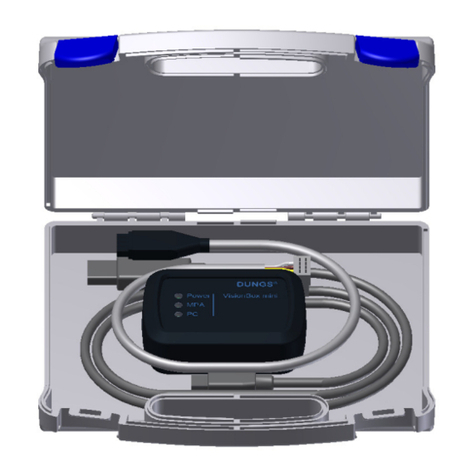
Dungs VisionBox User manual

Dungs

Dungs VisionBox User manual

Dungs DSLC px Vx Service manual

Dungs

Dungs DSLC px Vx Service manual

Popular Controllers manuals by other brands

Sunricher SR-ZV9003T3-RGBW-US Installation

Sunricher

Sunricher SR-ZV9003T3-RGBW-US Installation

Ksenia intro Installation and configuration manual

Ksenia

Ksenia intro Installation and configuration manual

Inovance CAN200 Series manual

Inovance

Inovance CAN200 Series manual

Gauzy LC6 FLEX Controller Installation and operation guide

Gauzy

Gauzy LC6 FLEX Controller Installation and operation guide

Viking SLP-1 Technical practice

Viking

Viking SLP-1 Technical practice

CKD KBX-30E-U Series instruction manual

CKD

CKD KBX-30E-U Series instruction manual

Sharp Energy Sun Flux User manual & installation guide

Sharp Energy

Sharp Energy Sun Flux User manual & installation guide

Yamaha RCX40 user manual

Yamaha

Yamaha RCX40 user manual

AB Quality PowerFlex 400 Frames D-H Service bulletin

AB Quality

AB Quality PowerFlex 400 Frames D-H Service bulletin

Yamaha MJC8 owner's manual

Yamaha

Yamaha MJC8 owner's manual

AL-KO ATC operating instructions

AL-KO

AL-KO ATC operating instructions

Savant SmartControl 2 Deployment guide

Savant

Savant SmartControl 2 Deployment guide

GameSir T3S user manual

GameSir

GameSir T3S user manual

Kostal inveor operating manual

Kostal

Kostal inveor operating manual

Emerson Yarway 20-55 Operating and safety instructions

Emerson

Emerson Yarway 20-55 Operating and safety instructions

CoCo ACM-LV24 Quick installation guide

CoCo

CoCo ACM-LV24 Quick installation guide

Brooks SLA5810/20 Installation and operation manual

Brooks

Brooks SLA5810/20 Installation and operation manual

SIGMA TEK SR 011 Technical manual

SIGMA TEK

SIGMA TEK SR 011 Technical manual

manuals.online logo
manuals.online logoBrands
  • About & Mission
  • Contact us
  • Privacy Policy
  • Terms and Conditions

Copyright 2025 Manuals.Online. All Rights Reserved.

1 … 16
M • Edition 11.12 • Nr. 220 977
Betriebs- und Montage-
anleitung
GasMultiBloc®
stufenlos gleitende
Betriebsweise
Typ MB-VEF B01
Nennweiten
Rp 1/2 - Rp 1 1/4
Operation and assembly
instructions
GasMultiBloc®
Gas-air-ratio control
Type MB-VEF B01
Nominal widths
Rp 1/2 - Rp 1 1/4
Notice d'emploi et de
montage
GasMultiBloc®
Réglage combiné du gaz
et de l'air
Typ MB-VEF B01
Diamètres nominaux
Rp 1/2 - Rp 1 1/4
Istruzioni di esercizio di
montaggio
GasMultiBloc®
con funzionamento a mo-
dulazione continua
Tipo MB-VEF B01
Diametri nominali
Rp 1/2 - Rp 1 1/4
Max. Betriebsdruck 360 mbar (36 kPa)
Max. operating pressure 360 mbar (36 kPa)
Pression de service maxi. 360 mbar (36 kPa)
Max. pressione di esercizio 360 mbar (36 kPa)
S10/12: p
e,min.
5 mbar (0,5 kPa) – p
e,max.
100 mbar (10 kPa)
S30/32:p
e,min.
100mbar(10 kPa)–p
e,max.
360mbar(36 kPa)
V1+V2 Klasse A, Gruppe 2
V1+V2 Class A, Group 2
V1+V2 Class. A, Groupe 2
V1+V2 Class A, Gruppo 2
nach / acc. / selon / a norme
EN 161
Klasse A, Gruppe 2
Class A, Group 2
Class A, Groupe 2
Class A, Grupo 2
nach / acc. / selon / a norme
EN 88, EN 12067-1
Un~(AC) 220 V-15 % …- 230 V+10 %
oder/or/ou/o
~(AC) 110 V - 120 V, ~(AC) 240 V,
=(DC) 48 V, =(DC) 24 V - 28 V
Einschaltdauer/Switch-onduration/
Dureé de mise sous tension/Durata
inserzione 100 %
Druckwächter/ Pressure Switch/
Pressostat/ Pressostato
Typ/Type/Type/Tipo
GW…A5, GW…A2, NB…A2, ÜB…A2
nach / acc. / selon / a norme
EN 1854
Verhältnis V
ratio V
Rapport V
rapporto valore V
pBr : pL
0,75 : 1 … 3 : 1
Nullpunktkorrektur N
Zero point adjustment N
Réglage du point zéro N
Spostamento a punto zero N
≈ ± 1 mbar (0,1 kPa)
Feinlter
Micro lter
Filtre n
Filtro ne
Umgebungstemperatur
Ambient temperature
Température ambiante
Temperatura ambiente
-15 °C … +70 °C
Schutzart
Degree of protection
Protection
Protezione
IP 54 nach / acc. / selon / a norme
IEC 529 ( DIN 40 050)
Familie 1 + 2 + 3
Family 1 + 2 + 3
Famille 1 + 2 + 3
Famiglia 1 + 2 + 3
Ausgangsdruckbereich
Output pressure range
Pression de sortie
Campo pressione in uscita
0,5 - 100 mbar (0,05 - 10 kPa)
[mbar]
EN 161
[ V ]
EN 88
V
1 : 1




IEC 529IEC 529
Gas Gaz



N
EN 1854
 
 
 
 
 
 
  

 
 
  
  
  
 
   
Elektrischer Anschluß
Electrical connection
Raccordement électrique
Allacciamento elettrico
IEC 730-1 (VDE 0631 T1)
Erdung nach örtlichen Vorschriften
Grounding acc. local regulations
Mise à la terre selon normes locales
Messa a terra secondo prescrizioni locali
S 10/S 30
P1
L1
P2
L2
Mp
N
P1
L1
Mp
N
P1
L1
P2
L2
Mp
N
P1
L1
Mp
N
S 12/S 32
P1
L1
MP
N
2
1
P2
L2
P1
L1
MP
N
1
2
3
Einbaulage
Installation position
Position de montage
Posizione di montaggio
NV
NV
NV
NV
2 … 16
M • Edition 11.12 • Nr. 220 977
Einbaumaße / Dimensions / Cotes d'encombrement / Dimensioni [mm]
g = Platzbedarf für Deckel des Druckwächters
g = space requirement for pressure switch cover
g = encombrement pour couvercle du pressostat
g = ingombro per il coperchio del pressostato
e = Platzbedarf für Magnetwechsel
e = space requirements for tting solenoid
e = Encombrement pour changement de l'électroaimant
e = Ingombro per sostituzione bobina
1,3,4,6
Verschlußschraube G 1/8
2 Meßstutzen
5 Verschlußschraube M4
7,8,9 Innengewinde G 1/8 für
Impulsleitungen p
L
, p
F
,p
Br
.
0 Filterdeckel
1,3,4,6
G 1/8 screwed sealing plug
2 Measuring nozzle
5 M4 screwed sealing plug
7,8,9
G 1/8 female thread for
pL,
pF,pBr pulse lines
0 Filter cup
1,3,4,6 Tappo a vite G 1/8
2 Presa per misuratore
5 Tappo a vite M4
7,8,9
letto interno G 1/8 per linee
ad impulsi pL, pF,pBr.
0 Coperchio del ltro
1,3,4,6 Bouchon G 1/8
2 Prise de pression
5 Bouchon M4
7,8,9 Taraudage G 1/8 pour le
raccordement des pres-
sions pL, pF,pBr.
0 Couvercle du ltre
Typ
Type
Type
Tipo
MB-VEF 407 B01
MB-VEF 412 B01
Druckabgrie
Pressure taps
Prises de pression
Manopola a pressione
ca
b
g
NV
f
d
e
Gewicht
Weight
Poids
Peso [kg]
3,45
5,90
Rp
Rp 3/4*
Rp 1 1/4*
Önungszeit
Opening time
Durée d'ouverture
Tempo aperutra
< 1 s
< 1 s
Pmax.
[VA]
28
50
Imax.
[A]
~(AC)
220 V .. 230 V
0,13
0,22
1
2
6
5
4
5
4
2
0
0
p , extern
PN1, DN 4
min. 5 x DN
p
p
ap
Br
p
ap
Br
Br
F
p
L
78
9
3
p
e
3
p
e
max. Drehmomente / Systemzubehör
max. torque / System accesories
max. couple / Accessoires du système
max. coppie / Accessorio di sistema
Geeignetes Werkzeug einsetzen! Schrauben kreuzweise anziehen!
Please use proper tools! Tighten screws crosswise!
Utiliser des outils adaptés! Serrer les vis en croisant!
Impiegare gli attrezzi adeguati! Stringere le viti incrociate!
DN
Rp
Mmax.
Tmax.
32
1 1/4
475 [Nm] t ≤ 10 s
160 [Nm] t ≤ 10 s
25
1
340
125
20
3/4
225
85
15
1/2
105
50
10
3/8
70
35
Gerät darf nicht als Hebel be-
nutzt werden
Do not use unit as lever.
Ne pas utiliser la vanne comme
un levier.
L'apparecchionondeveessere
usato come leva.
V
N
N
V
1
0
7
6
9
8
5
3
4
1
0
7
534
22

 

[Nm]
Typ
Type
Type
Tipo
MB-VEF 407 B01
MB-VEF 412 B01
a
110
140
b
151
185
c
120
145
d
160
175
e
185
245
f
70
80
g
40
40
Einbaumaße
Dimensions
Cotes d'encombrement
Dimensioni
[mm]
Einstellzeit
Setting time
Temps de réglage
Tempo di regolazione
EN 12067-1
< 1 s
< 1 s
Schaltungen/h
Switching ops/h
Enclenchements/h
Inerventi/h
60
60
M 5
5 Nm
M 6
7 Nm
G 1/8
5 Nm
G 1/4
7 Nm
G 1/2
10 Nm
G 3/4
15 Nm
M 8
15 Nm
M 4
2,5 Nm
M 10
25 Nm
3 … 16
M • Edition 11.12 • Nr. 220 977
Übersicht / Overwiew / Tableau récapitulatif / Sommario
1
2
3
4
5
6
7
8
9
10
11
12
13
14
15
16
17
18
Elektrischer Anschluß Druck-
wächter DIN EN 175 301-803
ElektrischerAnschlußVentile
DIN EN 175 301-803
Druckwächter
Eingangsansch
MeßanschlußG1/8vorFilter,
beidseitig möglich
Filter (unter Deckel)
Typenschild
Druckanschluß G 1/8
Gebläsedruck pL
Einstellschraube
Verhältnis V
peMeßanschluß G 1/8 vor
V1, beidseitig möglich
pBr Meßanschluß M4 nach
V2
Einstellschraube
Nullpunktkorrektur N
Druckanschluß G 1/8
Feuerraumdruck pF
Druckanschluß G 1/8
Brennerdruck pBr
Ausgangsansch
paMeßanschluß G 1/8 nach
V1, beidseitig möglich
Betriebsanzeige V1, V2
(optional)
Impulsleitung
Electrical connection for pressure
switch DIN EN 175 301-803
Electrical connection for valves
DIN EN 175 301-803
Pressure switch
Input ange
Test point connection G 1/8 upstream
of lter, possible on both sides.
Filter (below cover)
Type plate
G 1/8 pressure connection for pL
blower pressure
Setting screw, ratio V
Test pointconnectionG1/8 downstream
of lter possible of both sides
Test point connection M4 down-
stream of V2
Setting screw, zero point adjust-
ment N
G 1/8 pressure connection for pF
furnace pressure
G 1/8 pressure connection for pBr
burner pressure
Output ange
Test pointconnectionG1/8 downstream
of V1, possible on both sides
Operation display V1, V2
(optional)
Pulse line
Allacciamentoelettricopressostato
DIN EN 175 301-803
Allacciamentoelettricovalvole DIN
EN 175 301-803
Pressostato
Flangia in entrata
AttaccomisuratoreG 1/8prima del
ltro possibile sui due lati
Filtro (sotto il coperchio)
Targhetta
Attacco pressione G 1/8 per pres-
sione al soante pL
Vite di regolazione per rapporto
valore V
Attacco misuratore G 1/8 possible
sui due lati prima della V1
Attacco misuratore M4 dopo V2
Vite di regolazione per correzione
punto zero
Attacco pressione G 1/8 per pres-
sione al vano caldaia pF
Attacco pressione G 1/8 per pres-
sione al bruciatore pBr
Flangia in uscita
Possibile attacco misuratore G1/8
dopo V1 su entrambi i lati
indicatore di esercizio V1, V2
(optional)
Linee ad impulsi
Impulsleitungen sind nicht Bestandteil des Lieferumfangs.
Pulse lines are not part of our scope of delivery.
Notre fourniture ne comprend pas la tuyauterie de raccordement.
Le linee ad impulsi non costituiscono parte integrante della normale entita' di fornitura.
Raccordement électrique du pres-
sostat DIN EN 175 301-803
Raccordementélectriquedel'éctro-
vanne DIN EN 175 301-803
Pressostat
Bride d'entrée
Prise de pression G 1/8 avant le ltre
possible des deux côtés
Filtre sous le couvercle
Plaque signalétique
Raccordement G 1/8 pour la pres-
sion d'air pL
Vis de réglage du rapport V
Prise de pression G 1/8 avant des
deux côtés
Prise de pression M4 après V2
Vis de réglage de la correction du
point zéro N
Raccordement G1/8 pour la pres-
sion du foyer pF
Raccordement G 1/8 pour la pres-
sion du brûleur pBr
Bride de sortie
PrisedepressionaprèsV1 possible
des deux côtés
Indicateur de marche V1, V2
(option)
conduit d'impulsion
1
2
3
4
5
6
7
8
9
10
11
12 13
14
17
16
15
18
18 18
4 … 16
M • Edition 11.12 • Nr. 220 977
Gewindeanschausführung
MB- VEF B01
Ein- und Ausbau
1. Flansche auf die Rohrleitungen
montieren.GeeigneteDichtmittel
verwenden, Bild 1.
2.MB-VEFB01 einsetzen,Lage der
O-Ringe beachten, Bild 2.
3. Muttern A, B, C und D
anziehen,Bild 3.
4. Impulsleitungen pL, pFund pBr
anbringen.Seite 5 beachten!
5. Nach Einbau Dichtheits- und
Funktionskontrolle.
6. Ausbau in umgekehrter Reihen-
folge 4 ➞3 ➞2 ➞1.
Thread ange version
MB-VEF B01
Installation and disassembly
1. Mount ange onto tube lines. Use
appropriate sealing agent
(see Fig. 1)
2.InsertMB-VEFB01.Noteposition
of O-rings (see Fig. 2).
3.Tighten nuts A, B, C and D
(see Fig. 3).
4. Attach pulse lines pL, pFand pB.r
See note page 5!
5. Afterinstallation,performleakage
and functional test.
6. Disassembly in reverse order
4 ➞3 ➞2 ➞1.
Type à raccordement par brides
taraudées MB- VEF B01
Montage / Démontage
1. Visser les brides sur la tuyauterie,
utiliser de la pâte à joints appro-
priée Fig 1
2.MiseenplaceduMB-VEF,attention
aux joints toriques Fig 2.
3. Serrer les écrous A, B, C et D
Fig 3.
4.
Raccorderles conduitesd'impulsions
pL, pF
, pBr respecter les instructions de
montage de la page 5.
5. Contrôle de l'étanchéité et des
fonctions.
6. Pour le démontage suivre les
instructions dans le sens inverse
4 ➞3 ➞2 ➞1.
Esecuzione angia lettata MB-
VEF B01
Montaggio e smontaggio
1. montare la angia alle tubazioni
delle condutture. Utilizzare per
questo mastici adeguati: Fig.1
2. inserire l'apparecchio MB-VEF
B01eprestareparticolareatten-
zione agli O-Ring: Fig 2.
3. stringere i dadi A, B, C e D
Fig. 3.
4. montare le linee ad impulsi pL,
pFe pBr e prestare attenzione a
quanto prescritto a pag. 5
5. dopo il montaggio controllare la
tenuta ed il funzionamento.
6. lo smontaggio va effettuato
esattamente in senso inverso:
4 ➞3 ➞2 ➞1.
1 2
3 4
pBr
pF
pL
D
B
A
C
5 … 16
M • Edition 11.12 • Nr. 220 977
Montagevorschrift
Impulsleitungen
Impulsleitungen pL, pFund
pBR müssen ≥ DN 4 (ø 4 mm),
PN 1 entsprechen und aus Stahl
gefertigt sein.
Andere Werkstoe der Impulslei-
tungen nur nach Baumusterprü-
fungzusammenmitdem Brenner
zulässig.
Impulsleitungen müssen so
verlegt werden, daß kein
KondensatindenMB-VEFzurück-
ießen kann.
Impulsleitungen müssen si-
cher gegen Abriß und Verfor-
mung verlegt sein.
Impulsleitungen kurz halten!
Leitungen/Impulsleitungen
nachAnschlußaufatmosphä-
rische Dichtheit prüfen, Lecksuch-
spray nur gezielt einsetzen.
Prüfdruck: pmax. = 100 mbar
Pulse line
assembly instructions
Pulselines pL, pFand pBR must
correspond to ≥ DN 4 (4 mm
dia.), PN 1 and they must be made
of steel.
Other materials for pulse lines
are only permitted after a type
test together with the burner.
Route pulse lines so that no
condensate can ow back
to the MB-VEF.
Secure pulse lines to prevent
them from being ripped out
and deformed.
Keep of pulse lines short!
Test lines/impulse lines for
leakage to air. Use leakage
spray only if necessary.
Test pressure: p
max.
= 100 mbar
Instructions de montage des
conduites d'impulsions
Lesconduitesd'impulsionspL,
pFet pBR doivent être en acier
et avoir au moins PN1 et DN4.
Des conduites d'impulsions autres
qu' en acier ne pourront être utili-
sées qu' après des essais et une
homologation avec le brûleur.
Le montage des conduites
d'impulsions doit être réalisé
an d'éviter aux condensats de
s'introduire dans le MB-VEF.
Les conduites d'impulsions
doivent être protégées contre
l'arrachement et la déformation.
Les conduites d'impulsions doivent
être les plus courtes possible!
Un contrôle d'étanchéité des
conduitesseraréaliséaprèsle
montage.Attentiondansl'utilisation
d'un spray de détection de fuite.
Pression de contrôle: p
max.
= 100 mbar
Prescrizioni per il mo mtaggio
delle linee ad impulsi
Le linee ad impulsi pL, pFe pBR
devono essere ≥ a DN 4 (ø
4 mm), e corrispondere a PN 1 ed
essere prodotte in acciaio.
Altri materiali delle linee ad impulsi
sono consentiti soltanto dopo che
si sarà potuto collaudarne un cam-
pione insieme al bruciatore.
Le linee ad impulsi dovranno
esserestrutturatein modotale
che non sia possibile l'inltrazione
di condensa nell'apparecchio
MB-VEF.
Le linee ad impulsi dovranno
essere a prova di rottura e di
deformazione.
Mantenereperlelinee ad impulsi
un percorso breve
Dopo l'allacciamento control-
larela tenutaatmosfericadelle
condutture e delle linee ad impulsi.
Usare gli spray cercafughe soltanto
in modo orientato.
Pressione di prova: pmax. = 100 mbar
1 pe: Gaseingangsdruck
S10/12: 5 - 100 mbar
S30/32:100 - 360 mbar
7 pL: Gebläsedruck, Luft
0,4 - 100 mbar
8 pF: Feuerraumdruck
– 20 mbar … + 50 mbar
oder Atmosphäre
∆p
L
max. = p
L
- p
F
= 100 mbar
∆p
BR
max. = p
L
- p
F
= 100 mbar
9 pBr: Brennerdruck, Gas
0,5 - 100 mbar
1 pe: Gas inlet pressure
S10/12: 5 - 100 mbar
S30/32:100 - 360 mbar
7 pL: Blower pressure, air
0,4 - 100 mbar
8 pF: Combustion chamber
pressure or atmosphere
– 20 mbar … + 50 mbar
∆pL max. = pL - pF = 100 mbar
∆pBR max. = pL - pF = 100 mbar
9 pBr: Burner pressure, gas
0,5 - 100 mbar
1
p
e
: Pression d'entrée du gaz
S10/12: 5 - 100 mbar
S30/32:100 - 360 mbar
7 pL: Pression de l'air
0,4 - 100 mbar
8
p
F
: Pression du foyer
– 20 mbar … + 50 mbar
ou pression atmosphérique
∆pL max. = pL - pF = 100 mbar
∆pBR max. = pL - pF = 100 mbar
9 pBr:
Pression du brûleur, gaz
0,5 - 100 mbar
1
p
e
: pressione gas in entrata
S10/12: 5 - 100 mbar
S30/32:100 - 360 mbar
7 pL: pressione al soante,
aria 0,4 - 100 mbar
8
pF: pressione al vano caldaia
– 20 mbar … + 50 mbar
o atmosfera
∆p
L
max. = p
L
- p
F
= 100 mbar
∆p
BR
max. = p
L
- p
F
= 100 mbar
9 pBr:
pressione al bruciatore,
gas 0,5 - 100 mbar








Einbau Impulsleitungen
Installation of pulse lines
Montage des conduites d'impulsions
Installazione delle linee ad impulsi
S10/12:pmax. =100 mbar
S30/32:pmax. =360 mbar
V
N
N
V
1
0
7
6
9
8
5
3
4
1
0
7
534
22
1
2
6
5
4
5
4
2
0
0
p , extern
PN1, DN 4
min. 5 x DN
p
p
ap
Br
p
ap
Br
Br
F
p
L
78
9
3
p
e
3
p
e
6 … 16
M • Edition 11.12 • Nr. 220 977
pL, max. / maxi. = 100 mbar
pL, min. / mini. = 0,4 mbar
pBr, max. / maxi. = 100 mbar
pBr, min. / mini. = 0,5 mbar
pF, max. / maxi. = + 50 mbar
pF, min. / mini. = – 20 mbar
V = pBr : pL
Vmax. / maxi. = 3 : 1
Vmin. / mini. = 0,75 : 1
Nullpunktkorrektur ± 1 mbar
Zero point adjustment ± 1 mbar
Correction du point zéro ± 1 mbar
Correzione punto zero ± 1 mbar
Einstellmöglichkeiten
Adjustment possibilities
Possibilité de réglage
Possibilità di regolazione
Wirksamer Brennerdruck
Eective burner pressure
Pression utile du brûleur
Pressione eettiva al brucia-
tore
∆pBr = pBr – pF
Wirksamer Gebläsedruck
Eective blower pressure
Pression d'air utile
Pressione eettiva al soan-
te ∆pL= pL– pF
Einstellbereich
Setting range
Plage de réglage
Campo di regolazione
p
L
AIR
p
Br
GAS
p
F
Combustion
Atmosphere
V
min./mini.
max./maxi.
N
± 1 mbar
∆pL, min./mini. = 0,4 mbar
∆pL
Luft / Air / Aria
∆pBr
Gas / Gaz
{
+ N
∆pBr, min./mini. = 0,5 mbar
{
V = 0,75 : 1
V = 1 : 1
pBr, max./maxi. = 100 mbar
– N
pL, max./maxi. = 100 mbar
V = 0,75 : 1
V = 1 : 1
+ N
– N
V
Folgegröße
Resultant parameter
Conséquence
Grandezza sequenziale
Führungsgröße
Leading parameter
Conduite
Grandezza pilota
V = 3 : 1
V = 3 : 1
MB-VEF
Einstellbereich
Setting range
Plage de réglage
Campo di regolazione
∆pL
Luft / Air / Aria
∆pBr
Gas / Gaz
7 … 16
M • Edition 11.12 • Nr. 220 977
Plombierung
Plombierungsöse 2 in der Ver-
schlußklappe Ø 1,5 mm.
Plombierungsöse 3 in der Kreuz-
lochschraube Ø 1,5 mm.
NachEinstellungdesgewünschten
Drucksollwertes.
1. Schutzklappe 1 schließen.
2.
Draht durch 2 und 3 ziehen, Bild
2.
3.
PlombeumDrahtendendrücken,
Drahtschlaufe kurz halten.
Außerbetriebsetzen des
Druckregelteils: Anschluß ➞
pBr gasdicht verschließen.
Lead seal
Lead seal eye 2 in 1.5 mm dia.
sealing valve.
Lead seal eye 3 in 1.5 mm capstand
headed screw.
Aftersettingtherequestedpressure
setpoint:
1. Close protective valve 1.
2. Route wire through 2 and 3,
Fig. 2.
3. Press lead around wire ends,
keep wire loop short.
Setting pressure controller
out of operation: Seal con-
nection ➞p
Br
gas-tight.
Plombage
Oeillet de plombage 2 Ø 1,5 mm
dans le capuchon.
Oeillet de plombage 3 Ø 1,5 mm
dans la vis à tête percée.
Après le réglage.
1. Remettre le capuchon 1.
2. Passer le l de plombage dans
les trous 2 et 3 Fig 2.
3. Plomber en laissant une petite
boucle.
Neutralisationde la régula-
tion des pressions: mettre
un bouchon étanche au gaz sur
la conduite ➞pBr.
Piombatura
Occhielloperpiombaturanelcoper-
chietto Ø 1,5 mm.
Occhiello per piombatura n ella vite
a testa tonda forata Ø 1,5 mm.
Dopo la regolazione del valore di
pressione nominale desiderato:
1. chiudere il coperchietto
2. tirare il lo attraverso i punti 2 e
3 (Fig.2)
3. piombare le estremità del lo la-
sciando corto l'anello passante
Messa fuori servizio del
gruppo regolazione-pres-
sostato: sigillare a tenuta/gas
l'attacco ➞pBr.
1 2
2
3
05/97
1
MB-VEF B01
Einstellung des Druckregelteils
Druckregelteil ist werks-
seitig voreingestellt. Die
Einstellwerte müssen vor Ort
den Anlagenbedingungen an-
gepaßt werden. Anleitung des
Brennerherstellers unbedingt
beachten!
1. Schutzkappen V und N önen.
2. Brenner starten, Korrektur der
Einstellwerte N und V nur im
Betrieb möglich, Bild 1
3. Zündsicherheit des Brenners
überprüfen.
4. Bei min. Leistung:
Nullpunktkorrektur N einstellen.
5. Bei max. Leistung:
Verhältnis V einstellen.
6. Wenn notwendig Einstellung 4.
und 5. wiederholen.
Zwischenwerte kontrollieren.
7. EinstellschraubenNundV plom-
bieren, siehe unten.
OptimaleVerbrennung und
Zündsicherheit muß sicher-
gestellt sein!
MB-VEF B01
Setting the pressure controller
Pressure controller is pro-
visionally set at the fac-
tory. The setting values must
be locally adapted to machine
conditions. Important: Follow
the instructions of the burner
manufacturer.
1. Open protective caps V and N.
2. Startburner.Adjustmentofsetting
values N and V only possible in
operation, Fig. 1
3. Check ignition reliability of
burner.
4. At min. performance:
Set zero point adjustment N.
5. At max. performance:
Set ratio V.
6. If necessary, repeat settings 4.
and 5. Check intermediate val-
ues.
7. Seal setting screws N andV (see
below) with lead.
Ensure optimum combus-
tion and ignition reliability!
MB-VEF B01
Réglage des pressions
Ils sont préréglés en usine.
Ces réglages doivent être
ajustés lors de la mise en route
de l'installation suivant les indi-
cations et recommandations du
constructeur des brûleurs!
1. Enlever les capuchons V et N.
2.
Démarrer le brûleur, la correction
desvolumesNetVsontpossibles
uniquement en marche, Fig. 1
3. Contrôlerle temps desécuritédu
brûleur.
4. Adébitmini:réglageducorrecteur
du point zéro N.
5.
A débit maxi: réglag du rapport V.
6. Répéter les réglages 4 et 5 si
nécessaire.
Contrôlerlesvaleursintermédiai-
res.
7.
Plombage des vis de réglage N et
V.
Il faut s'assurer que la
combustion et le temps de
sécurité sont bien réglés!
MB-VEF B01
Taraturadel gruppo regolazione-
pressione
Il gruppo regolazione-pres-
sione viene pre-tarato in
fabbricaIvaloriditaraturadevono
essere poi adattati sul posto alle
esigenze dell'impianto. Prestare
assolutamente attenzione alle
istruzioniindicate dalfabbricante
del bruciatore!
1. aprire i coperchietti V e N.
2.
avviare il bruciatore, le correzioni dei
valori N e V sono possibili solo con
l'apparecchio in funzione,Fig. 1.
3. controllare la sicurezza di accen-
sione del bruciatore
4. a potenza minima/correggere N
a punto zero
5. a potenza massima/regolare il
valore di rapporto V
6. se necessario ripetere le regola-
zioni dei punti 4 e 5 e controllare
i valori intermedi.
7. Piombare le viti di regolazione N
e V (vedere qui sotto).
Dovranno essere raggiunte
sia una combustione che
una sicurezza di accensione
ottimali!
Innensechskantschlüssel No. 2,5
Allen key no. 2.5
Clé de six pans mâle no 2,5
Chiave esagonale cava nr. 2,5
8 … 16
M • Edition 11.12 • Nr. 220 977
2
Druckwächter am Einstellrad mit
SkalaaufvorgeschriebenenDruck-
sollwert einstellen, Bild 2.
Anleitung des Brennerher-
stellers beachten!
Druckwächterschaltetbeifallendem
Druck: Einstellung ➞.
Haube wieder aufsetzen!
Setthepressureswitchatthesetting
wheel to the specied pressure set-
point using the scale, Fig. 2.
Please follow the instruc-
tions of the burner manu-
facturer!
Pressure switch switches as pres-
sure reduces:
Set to ➞.
Remount hood!
Einstellung des Gasdruckwäch-
ters MB- VEF B01
Haube mit geeignetem Werkzeug
demontieren,Schraubendreher Nr.
3 bzw. PZ 2, Bild 1.
Haube abnehmen.
Setting the gas pressure switch
MB- VEF B01
Dismount the hood using a suitable
tool, e.g. screwdriver no. 3 or PZ 2,
Fig. 1. Remove hood.
1
Régler le pressostat avec son bou-
ton à la valeur désirée Fig 2.
Respecter les recomman-
dations du constructeur
du brûleur!
Le pressostat commute par la pres-
sion descendante: régler sur ➞.
Remonter le capot!
Tarare il pressostato, come in gura
2, sul valore di pressione nominale
prescritto,agendosullarotella della
scala graduata.
Prestare attenzione alle
istruzioni indicate dal fa-
bbricante del bruciatore!
Il pressostato scatta con pressione
in discesa: regolazione sulla ➞.
Rimontare la calotta!
Réglage des pressostats gaz du
MB-VEF B01
Enlever les vis du capot en utilisant
un tournevis no 3 respectovement
PZ 2, Fig 1.
Enlever le capot.
Regolazionedel pressostatogas
per MB- VEF B01
Smontare la calotta con un attrezzo
adeguato, ossia cacciavite nr. 3 -
rispettiv, PZ 2, gura 1
Togliere la calotta.
Made in Germany
IP 54
NO NC
21
2
8
3
4
5
6
7
9
10
mbar
GW 10 A5
pmax.= 500 mbar Gas
~(AC) 50-60Hz 10A 250V
15T70
ID.No:CE-0085
AO 0012
Made in Germany
IP 54
9 … 16
M • Edition 11.12 • Nr. 220 977
MB- VEF B01
Filterkontrolle
Filterkontrolle mindestens
einmal jährlich!
Filterwechsel, wenn ∆p
zwischen Druckanschluß 0
und 2 > 10 mbar.
Filterwechsel, wenn ∆p zwi-
schen Druckanschluß 0 und 2
imVergleichzurletztenKontrolle
doppelt so hoch ist.
Filterwechselkannohne Ausbau
der Armatur erfolgen.
1. Gaszufuhr unterbrechen: Kugel-
hahn schließen
2. Schrauben 1,2,3,4 mit Innen-
sechskantschlüssel No. 3 he-
rausdrehen, Filterdeckel 5 ab-
nehmen.
3. Filtereinsatz6entnehmen,gegen
neuen Filtereinsatz tauschen,
Bild 1
4. Filterdeckel5aufsetzen,Schrau-
ben 1,2,3,4 ohne Gewalt hinein-
drehen und anziehen.
5. Funktion und Dichtheitsprüfung
durchführen.
Druckanschluß über Verschluß-
schraube 3 pmax. = 360 mbar
Bei häugem Filterwechsel:
SelbstfurchendeSchrauben
durch Schrauben M4 x 14 mit me-
trischem Gewinde ersetzen.
MB- VEF B01
Filter check
Check the filter at least
once a year!
Change the lter, if ∆p be-
tween pressure connection 0
and 2 > 10 mbar.
Change the filter, if ∆p
between pressure connec-
tion 0 and 2 is twice as high
compared to the last check.
You can change the lter without
removing the tting.
1. Stop gas supply, close ball
cock.
2. Unscrew screws 1, 2, 3, 4 using
the Allen key no. 3. Remove lter
cover 6.
3. Remove lter 6 and replace with
new one, Fig. 1.
4. Put lter cover 5 on, screw in
screws 1, 2, 3, 4 without using
any force and fasten.
5. Perform functonal and leakage
tests.
Pressureconnection overscrewed
sealing plug 3 pmax = 360 mbar.
For frequent lter change:
Replaceself-tappingscrews
by M4 x 14 screws with metric
thread.
MB- VEF B01
Vérication du ltre
Vérication du ltre: mini-
mum une fois par an!
Remplacement du ltre: si
le ∆p entre prise de pression
0 et 2 est > 10 mbar.
Remplacement du ltre:
le
∆p entre prise de pression 0
et 2 a doublé par rapport à la
dernière mesure.
Le remplacement du ltre peut
se réaliser sans démonter le
MultiBloc
1. Couper l'alimentation en gaz.
Fermer le robinet à boisseau
sphérique.
2. Dévisser les vis 1,2,3,4 avec une
clé de six pans mâle no 3.Oter le
couvercle 5 du ltre.
3. Remplacer l'élémen ltrant 6 par
un élément neuf Fig 1.
4. Mise en place du couvercle 5
puis des vis 1, 2, 3 ,4.Serrer avec
modération.
5. Contrôle de la fonction et de
l'étanchéité.
Prise de pression par la vis 3 pmax.
= 360 mbar
Pour un échange fréquent
de l'élément ltrant, rem-
placer les vis autotaraudeuses
par des vis M4 x 14 à pas mé-
trique.
MB- VEF B01
Controllare del ltro
Controllare yil ltro almeno
1 volta l'anno!
Cambiare, il ltro se il ∆p fra
gli attacchi pressione 0 e 2 é
> di 10 mbar.
Cambiare, il ltro se il ∆p fra
gli attacchi pressione 0 e 2
al confronto con l'ultimo con-
trollo si é raddoppiato
Il cambio del ltro può essere
eettuato senza smontare l'ar-
matura.
1. interrompere l'ausso del gas
chiudendo il rubinetto a sfera.
2. Svitare le viti 1, 2, 3, 4 con chiave
esagonale cava nr. 3 e togliere il
coperchio del ltro.
3. Togliere il ltrino 6 e sostituirlo
con uno nuovo, Figure 1.
4. inserire il coperchio 5 riavvitare e
stringere senza sforzo le viti 1, 2,
3, 4.
5. Eettuare una prova di funzio-
namento e di tenuta Attacco
pressione attraverso la vite di
chiusura 3 pmax. = 360 mbar
In caso di sostituzione fre-
quente del ltro: sostituire
le viti autolettanti con delle viti
M4 x 14 con lettatura metrica.
Beachte:BeiAnwendungen
mit großen Durchußmen-
gen einen separaten Gaslter
vorschalten! Bild 2.
MB-VEF 407 B01 > 15 m3/h
DUNGS Gasfilter Typ GF 510
einsetzen.
MB-VEF 412 B01 > 35 m3/h
DUNGS Gasfilter Typ GF 515
einsetzen.
Der im MultiBloc eingebaute Filter
kann dann entfallen.
Attenzione: Se vengono
utilizzate grosse portate
inserire anche un ltro gas se-
parato (Vedi Fig.2)
MB-VEF 407 B01 > 15 m3/h
utilizzare ltro DUNGS tipo GF 510
MB-VEF 412 B01 > 35 m3/h
utilizzare ltro DUNGS tipo GF 515.
Inquestocaso puòesseretralasciato
il ltro montato sul MultiBloc.
Attention: Pour un débit
important, monter un ltre
gaz en amont Fig 2.
MB-VEF 407 B01 > 15 m3/h
monter le ltre DUNGS type GF
510.
MB-VEF 412 B01 > 35 m3/h
monter le ltre DUNGS type
GF 515.
Dans ce cas on peut enlever le ltre
du MultiBloc.
Note: When using large
ow volumes, add a sepa-
rate gas lter (see Fig. 2)
MB-VEF 407 B01 > 15 m3/h
Insert DUNGS gas lter, type GF
510.
MB-VEF 412 B01 > 35 m3/h
Insert DUNGS gas lter, type
GF 515.
The lter installed in the MultiBloc
is not required then.
2
6
1
5
1
3
2
4
10 … 16
M • Edition 11.12 • Nr. 220 977
Beispiel Geräteauswahl
Bekannt:
pe = 20 mbar
Arbeitspunkt Vmax. = 25 m3/h
PBr, max. = 11 mbar
Arbeitspunkt Vmin. = 8,3 m3/h
Zu bestimmen:
∆P
min.
= 20 mbar – 11 mbar = 9 mbar
Es gilt:
r = Qmax. / Qmin. = Vmax. / Vmin.
r = 25 / 8,3 = 3
pBr, min. = pBr, max. / r2
PBr, min. = 11 / 9 = 1,2 mbar
∆ P max. = pe– pBr, min.
∆pmax. = 20 mbar – 1,2 mbar
∆pmax. = 18,8 mbar
Ergebnis Arbeitspunkt 1 mit:
Vmax. = 25 m3/h
∆pmin. = 9 mbar
Ergebnis Arbeitspunkt 2 mit:
Vmin.. = 8,3 m3/h
∆pmax. = 18,8 mbar
Geräteauswahl: MB-VEF 412 B01
Beide Arbeitspunkte müs-
sen im empfohlenen Ar-
beitsbereich einer Baugröße
liegen!
Durchuß-Diagramm1 / Flow Diagram1 / Courbe des débits 1 / Diagramma di portata 1
Kurven für Geräteauswahl MB- 407/412 (im eingeregelten Zustand), mit Normlter
Curves for equipment selection: MB 407/412 (in regulated state), with standard lter
Courbes pour la sélection des MultiBlocs 407/412 (réglage eectué) avec ltre aux normes
Curve per la scelta del tipo di apparecchio MB 407/412 (in condizioni già preregolate), con ltro normale
Example: Equipment selection
Known:
pe = 20 mbar
Work point Vmax. = 25 m3/h
PBr, max. = 11 mbar
Work point Vmin. = 8,3 m3/h
To be determined:
∆P
min.
= 20 mbar – 11 mbar = 9 mbar
The following applies:
r = Qmax. / Qmin. = Vmax. / Vmin.
r = 25 / 8,3 = 3
pBr, min. = pBr, max. / r2
PBr, min. = 11 / 9 = 1,2 mbar
∆Pmax. = pe– pBr, min.
∆pmax. = 20 mbar – 1,2 mbar
∆pmax. = 18,8 mbar
Result work point 1:
Vmax. = 25 m3/h
∆pmin. = 9 mbar
Result work point 2:
Vmin.. = 8,3 m3/h
∆pmax. = 18,8 mbar
Equipment: MB-VEF 412 B01
Both work points must be
within the recommended
working range of a size!
Exemple de sélection
Connu:
pe = 20 mbar
Point de travail Vmax. = 25 m3/h
PBr, max. = 11 mbar
Point de travail Vmin. = 8,3 m3/h
A déterminer:
∆P
min.
= 20 mbar – 11 mbar = 9 mbar
Soit:
r = Qmax. / Qmin. = Vmax. / Vmin.
r = 25 / 8,3 = 3
pBr, min. = pBr, max. / r2
PBr, min. = 11 / 9 = 1,2 mbar
∆Pmax. = pe– pBr, min.
∆pmax. = 20 mbar – 1,2 mbar
∆pmax. = 18,8 mbar
Résultat point de travail 1:
Vmax. = 25 m3/h
∆pmin. = 9 mbar
Résultat point de travail 2:
Vmin.. = 8,3 m3/h
∆pmax. = 18,8 mbar
MultiBloc: MB-VEF 412 B01
La sélection des 2 points
de travail devra se situer
dans la plage de travail d'un
MultiBloc donné!
Esempio per la scelta di un
apparecchio
Conoscinto:
pe = 20 mbar
Punto di lavoro Vmax. = 25 m3/h
PBr, max. = 11 mbar
Punto di lavoro Vmin. = 8,3 m3/h
Da determinare:
∆P
min.
= 20 mbar – 11 mbar = 9 mbar
Vale:
r = Qmax. / Qmin. = Vmax. / Vmin.
r = 25 / 8,3 = 3
pBr, min. = pBr, max. / r2
PBr, min. = 11 / 9 = 1,2 mbar
∆Pmax. = pe– pBr, min.
∆pmax. = 20 mbar – 1,2 mbar
∆pmax. = 18,8 mbar
Risultato punto di lavoro 1 con:
V
max.
= 25 m3/h
∆pmin. = 9 mbar
Risultato punto di lavoro 2 con:
Vmin.. = 8,3 m3/h
∆pmax. = 18,8 mbar
Apparecchio: MB-VEF 412 B01
Entrambi i punti di lavoro
dovrannotrovarsinelcam-
po di lavoro consigliato di una
grandezza
costruttiva.
∆p [mbar]
2 3 4 5 6 7 8 910 20 30 40 60 80 100 200
2 3 4 5 6 7 8 910 20 30 40 60 80 100 200
Basis + 15° C, 1013 mbar, trocken
Based on + 15° C, 1013 mbar, dry
Base + 15° C, 1013 mbar, sec
Base + 15° C, 1013 mbar, secco
Vn [m3/h] Luft / Air / Aria dv = 1,00
°
Vn [m3/h] Erdgas/Natural gas/Gaz Naturel/Gas metano dv = 0,65
°
2
3
4
5
6
1
8
10
20
30
40
60
80
100
50
200
300
360
150
MB-VEF 407 B01 Rp 3/4
empfohlener Arbeitsbereich
recommended endeavor
zone de travail recommandée
campo di lavoro raccomandato
∆p [mbar]
2 3 4 5 6 7 8 9 10 20 30 40 60 80 100 200
2 3 4 5 6 7 8 9 10 20 30 40 60 80 100 200
Basis + 15° C, 1013 mbar, trocken
Based on + 15° C, 1013 mbar, dry
Base + 15° C, 1013 mbar, sec
Base + 15° C, 1013 mbar, secco
Vn [m3/h] Luft / Air / Aria dv = 1,00
°
Vn [m3/h] Erdgas/Natural gas/Gaz Naturel/Gas metano dv = 0,65
°
2
3
4
5
6
1
8
10
20
30
40
60
80
100
50
200
300
360
150
MB-VEF 412 B01 Rp 1 1/4
empfohlener Arbeitsbereich
recommended endeavor
zone de travail recommandée
campo di lavoro raccomandato
2
1