manuals.online logo
Brands
  1. Home
  2. •
  3. Brands
  4. •
  5. Dungs
  6. •
  7. Controllers
  8. •
  9. Dungs CP -9302-702 User manual

Dungs CP -9302-702 User manual

1 … 4 1 … 4
Karl Dungs Inc.
524 Apollo Drive, Suite 10 Lino Lakes, MN 55014 U.S.A.
Phone: (651) 792-8912 Fax: (651) 792-8919 E-mail: [email protected]
Ambient Temperature
-40°F to +160°F (-40˚C to +71˚C)
Enviroment
NEMA TYPE 4 (weathertight)
Open circut Input
Drives actuator to low
Series Operation
No offset in control point when operated in tandem
Approvals
UL Listed
CP-9302-702 Actuator Drive
Installation Instructions
SPECIFICATIONS
The CP-9302-702 electronic actuator drive processes a variable input signal from a controller to provide proportional control of
an electric actuator. The CP-930-702 is preset for current input (4-20 mA) and has additional wiring for connection to an over-
ride switch for applications requiring an external override of the input signal. The CP-9302-702 is equipped with built in jumpers
and adjustable potentiometers, so that the type of input signal, deadband, input span, and start point may be readjusted in the
field when necessary.
Electrical Ratings
Power supplied by the actuator
Input: 4-20 mA
Electrical Connection
1/2” conduit knockout
Deadband Adjustability (Hysteresis)
Factory set at 5%, adjustable to 3%
Grounded Input
Grounding either or both input wires will not cause
damage
• Inspect unit before installing, look for bent or broken
parts or oil leaks from actuator.
• Use NEMA TYPE 4 compatible type connectors.
• Observe the barrier that separates the line voltage ter-
minals from the low voltage which controls the actuator
motor.
• All connections to the line voltage side of the barrier (L1
and L2, 1, 5 and 6 terminals) must be made with Class 1
wiring; connections to the remaining terminals can be
Class 2 thermostat cable if desired.
• Allow 6 inches (152mm) clearance above the actuator
wiring compartment.
Installation must be done by a qualified, licensed
technician. The system must meet all applicable
codes. Improper system design or setup may
cause explosions, property damage, and injuries.
• Disconnect all power to the valves before wiring to
prevent electrical shock and equipment damage.
• Do not exceed the electrical ratings given in the
specifications and on the actuator.
• Attach a exible 1/2” conduit to the actuator.
• Route the wires through the conduit.
• Use 14 or 16 guage wire for at least 75˚C (167˚F).
• Connect the wiring to the appropriate screw terminals.
• Remove the appropriate knock out on the side you wish
to mount the sidebox.
• Insert the sidebox into the actuator and leaving the
O-ring on the sidebox.
• Secure the sidebox to the actuator with the conduit
locknut provided.
CP-903-702 Installation Manual - P/N 80104 - Ed. 01/08
ATTENTION
• Read these instructions carefully.
• Failure to follow them and/or improper installation may
cause explosion, property damage and injuries.
• Installation must be done with the supervision of a
licensed burner technician.
• The system must meet all applicable national and local
code requirements such as but not limited to NFPA 86,
CSD-1, ANSI Z21.13, UL 795, NFPA 85, or CSA B149.3.
• Check the ratings in the specications to make sure that
they are suitable for your application.
• Never perform work if gas pressure or power is applied,
or in the presence of an open ame.
• Once installed, perform a complete checkout.
• Verify proper operation after servicing.
Power Equipment Company
2011 Williamsburg Road Richmond, VA 23231 USA
Phone: 804.236.3800 Fax: 804.236.3882 E-Mail: [email protected]
2 … 4
WIRING
WARNING: Overriding the imput signal will drive the
actuator to the mechanical end of travel.
WARNING: Do not apply line voltage to terminals
“X”, 2,3,4,7or 8 or the motor will be permanently
damaged.
Inspect unit before installing, look for broken parts or leaks.
Use NEMA TYPE 4 compatible type connectors.
Observe the barrier that separates the line voltage terminals
from the low voltage which operates the actuator motor. All
connections to the line voltage side of the barrier (L1 and L2,
1, 5 and 6 terminals) must be made with Class 1 wiring; con-
nections to the remaining terminals can be Class 2 thermostat
cable if desired.
Allow 6 inches (152mm) clearance above the actuator wiring
compartment.
INSTALLATION
• Disconnect all power to the valves before wiring to
prevent electrical shock and equipment damage.
• Do not exceed the electrical ratings given in the
specifications and on the actuator.
• Attach a exible 1/2” NPT conduit to the actuator.
• Route the wires through the conduit.
• Use 14 or 16 guage wire for at least 105˚C (221˚F).
• Connect the wiring to the appropriate terminals.
Do not adjust the limit switch beyond 90° unless the standard
slidewire has been replaced with a 180° slidewire; do not adjust
beyond 180° for proportioning control.
In some applications, a Flame Safeguard (FSG) may have
one or two overriding circuits. One being a low re purge
start and the other a high fire pre-purge. The function of
the violet/white and violet wires are to provide an electrical
connection so that the FSG can override, the temperature
controller and drive the air damper actuator without a 4mA
signal. If such connections are not needed in the application,
simply tape them off, and safely stow away.
Low Voltage
FACTORY CONFIGURATION REVEARSE CONFIGURATION
3 … 4
ADJUSTMENT
CAUTION: Do not apply a voltage source input to
CP-9302 actuator drive that is configured for current
input. Doing so may damage the drive.
CAUTION: Static charges produce voltages high
enough to damage the electronic components. Fol-
low static electricity precautions when servicing the
device(s).
Figure 2
If a CP-9302-702 requires adjustments to its startpoint, or input span, make adjustments according to the following:
CP-9302-702 Adjustment (Preparation)
From the factory, the actuator is calibrated such that it drives
to 90 degrees with 20mA applied and 0 degrees with 4mA
applies. To reduce the 90 degree position or increase 0
degree position, following the procedure below.
Initial Setup
1. Turn off all power and input signals to the actuaton.
2. Remove the metal cover. This allows access to the poten-
tiometers and the input/deadband jumpers.
3. Disconnect the drive’s yellow and blue leads from the
controller.
4. Connect the drive’s leads to the corresponding lead on
an instrument capable of producing 4-20mA +/- 0.1mA
(current calibrator).
Minimum Position Calibration
1. Apply power to the actuator, then turn on the “current
calibrator”.
2. Adjust the “current calibrator” until the mA input equals
the desired zero point current. This is typically 4mA.
NOTE: The minimum position current input (zero point)
potentiometer and maximum position current input (span)
potentiometer can be physically turned indefinitely; but
they have an effective limit of 25 turns. Relative to the
start point (4 mA / 0 degrees), rotating the post CW
causes the actuator to drive toward 90 degrees. Con-
versely rotating the pots CCW causes the actuator to
drive back toward zero. This is true of both the START
POINT and SPAN adjustments.
NOTE: There is a slight delay (approx. 3 seconds) in actua-
tor movement when a potentiometer is adjusted. Make
final adjustments slowly to prevent over adjusting. If
adjusted properly, when the unit just begins to drive, it
should stop within 5 degrees. Over adjusting will lower
the actual start point.
3. With the desired current input for the minimum position
applied (typically 4mA), adjust the zero point potentiometer
so the actuator shaft drives to it’s zero point (minimum po-
sition). It is best to adjust the start point potentiometer until
the actuator shaft just starts to move off its zero point.
Maximum Position Calibration
1. Apply power to the actuator, then turn on the “current
calibrator”.
2. Adjust the “current calibrator” until the mA input equals the
desired finish point (maximum position). This is typically
20mA.
3. With the desired current input for maximum position (typi-
cally 20mA), the actuator will drive towards 90 degrees.
Once the actuator stops, adjust the span potentiometer
so the actuator shaft drives to the maximum position. It
is best to adjust the span potentiometer until the actuator
shaft just moves to its finish point.
4 . Remove the current calibrator and turn off power to the
actuator. Then, reconnect the drive’s leads to the control-
ler.
5. Reinstall the cover.
6. Reapply power to the actuator and turn on the controller .
NOTE: Occasionally, an adjustment to the input span setting
results in a change to the start point setting, due to a small
interaction between these two settings. After adjusting the
input span potentiometer, ensure that both settings meet
requirements by repeating steps 7 - 9.
NOTE: When setting the potentiometers; only move the
actuator shaft in one direction. If the shaft is moved in the
opposite dirrection, the deadband will affect the setting.
Metal cover of
CP-9302-702
Location of pot.
adjustments and
jumpers under
metal cover
Top view of CP-9302-702
(the black box)
Potentiometer Adjustments and Jumpers
4 … 4
DIMENSIONS
TESTING
When replacing a CP 8391-703 control unit with a
CP 9302 702 in NEMA TYPE 4 applications a seal
must be installed into the unused conduit knock out
to maintain NEMA TYPE 4 rating.
Test 1: Connect the drive’s leads to the corresponding
lead of a suitable current signal source (current calibrator).
Apply power to the actuator, then turn on the current signal
source (current calibrator). Adjust the current signal source
(current calibrator) until the mA meter reading equals the
desired zero point current (2 to 16 mA). Adjust the current
signal source (current calibrator) until the mA meter reading
equals the finish point current. With the desired finish point
current applied, the actuator shaft should drive to the finish
point. If the actuator fails this test repeat the CP-9302-702
Adjustment section. Short the Violet/White wire to the
Violet wire; the actuator shaft should turn counterclockwise.
Short the Violet/White wire to the Bluewire; the actuator
shaft should turn clockwise. When you break the connection
between the Violet/White and Violet wires, the shaft should
return fully clockwise. If the actuator fails this test, perform
Test 2.
Test 2: Disconnect the Yellow/Black wire from terminal “X”.
Jumper actuator terminal “X” to terminal 2; the actuator shaft
should turn clockwise. When the connection between termi-
nals “X” and 2 is broken, the shaft should remain stationary.
Then jumper terminal “X” to terminal 3; the shaft should turn
counterclockwise. If the actuator passes this test, but failed
Test 1, the side-mounted control box is defective and must
be replaced.
If the unit failed both tests, the actuator itself is defective and
must be replaced. Contact Dungs for replacement informa-
tion.

Other Dungs Controllers manuals

Dungs VisionBox User manual

Dungs

Dungs VisionBox User manual

Dungs VPM-LC Service manual

Dungs

Dungs VPM-LC Service manual

Dungs hiltbrand DGAI. 69F Product guide

Dungs

Dungs hiltbrand DGAI. 69F Product guide

Dungs GasMultiBloc MB-ZRD B01 Series User manual

Dungs

Dungs GasMultiBloc MB-ZRD B01 Series User manual

Dungs DGAI. 27F/3 Service manual

Dungs

Dungs DGAI. 27F/3 Service manual

Dungs DSLC px Vx Service manual

Dungs

Dungs DSLC px Vx Service manual

Dungs FRM 100065 User manual

Dungs

Dungs FRM 100065 User manual

Dungs FRSBV 10010 Series User manual

Dungs

Dungs FRSBV 10010 Series User manual

Dungs MultiBloc MBC-VEF Series Service manual

Dungs

Dungs MultiBloc MBC-VEF Series Service manual

Dungs GasMultiBloc MB-D 055 D01 Service manual

Dungs

Dungs GasMultiBloc MB-D 055 D01 Service manual

Dungs MultiBloc MBC-SE Series Service manual

Dungs

Dungs MultiBloc MBC-SE Series Service manual

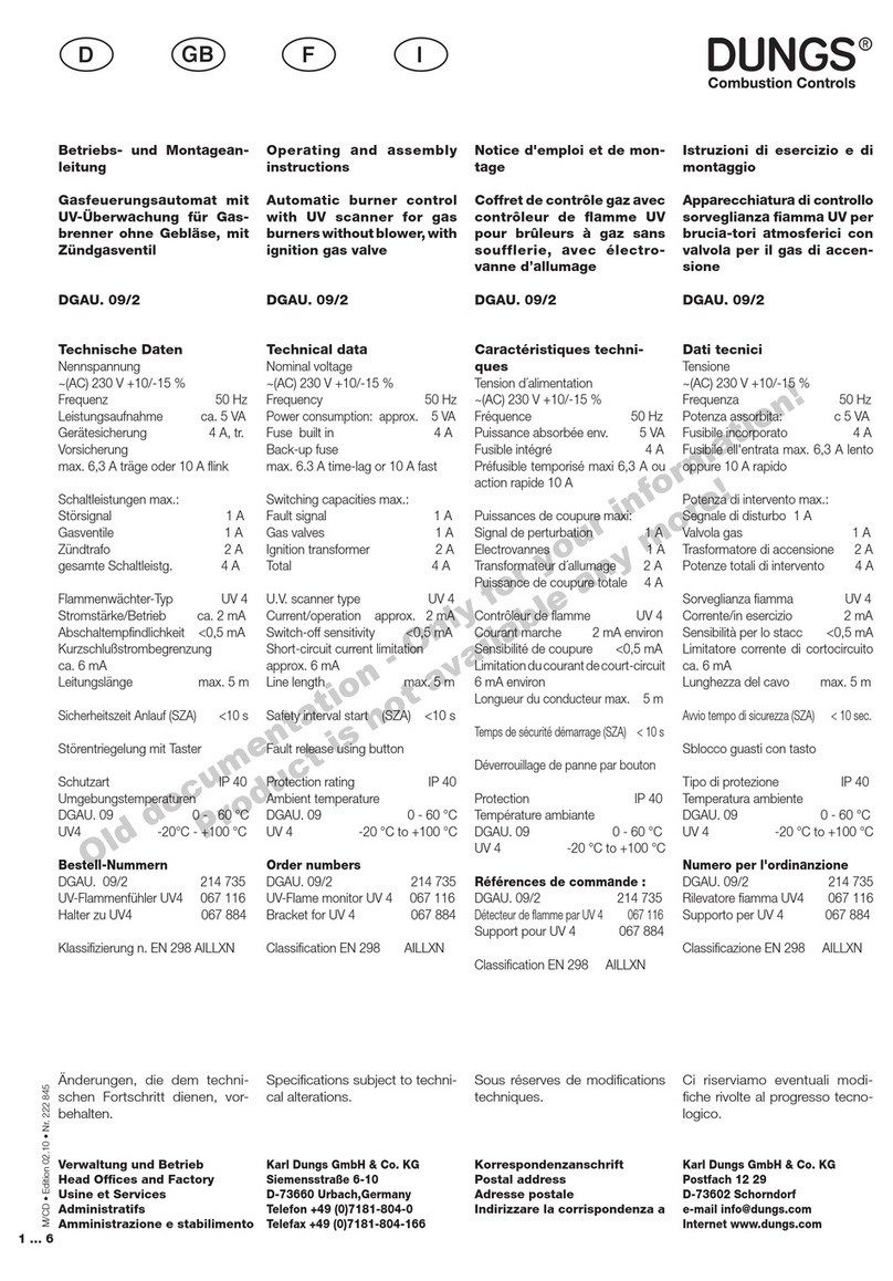
Dungs DGAU. 09/2 Product guide

Dungs

Dungs DGAU. 09/2 Product guide

Dungs EMP-5 User manual

Dungs

Dungs EMP-5 User manual

Dungs FRM Series User manual

Dungs

Dungs FRM Series User manual

Dungs DMA User manual

Dungs

Dungs DMA User manual

Dungs DGAI. 131F User manual

Dungs

Dungs DGAI. 131F User manual

Dungs GasMultiBloc MB 403 B01 Series User manual

Dungs

Dungs GasMultiBloc MB 403 B01 Series User manual

Dungs GasMultiBloc MB-D B01 Series User manual

Dungs

Dungs GasMultiBloc MB-D B01 Series User manual

Dungs GasMultiBloc MB-ZRD B07 Series Service manual

Dungs

Dungs GasMultiBloc MB-ZRD B07 Series Service manual

Dungs FRM 100025 ND User manual

Dungs

Dungs FRM 100025 ND User manual

Dungs FRM 100065 User manual

Dungs

Dungs FRM 100065 User manual

Dungs FRI 7/6 Series User manual

Dungs

Dungs FRI 7/6 Series User manual

Dungs GasMultiBloc MB-VEF B01 Service manual

Dungs

Dungs GasMultiBloc MB-VEF B01 Service manual

Dungs MPA22 Service manual

Dungs

Dungs MPA22 Service manual

Popular Controllers manuals by other brands

Banner PresencePLUS PRC1 instruction manual

Banner

Banner PresencePLUS PRC1 instruction manual

Watlow ez-zone pm user manual

Watlow

Watlow ez-zone pm user manual

Linear Technology DC1488A Series manual

Linear Technology

Linear Technology DC1488A Series manual

Marlec HRDi Installation and operation

Marlec

Marlec HRDi Installation and operation

Areca ARC-1883 Series quick start guide

Areca

Areca ARC-1883 Series quick start guide

SEW DHE41B manual

SEW

SEW DHE41B manual

Conotec FOX-2003SJ-1 instruction manual

Conotec

Conotec FOX-2003SJ-1 instruction manual

ICP DAS USA I-7188XB Series user manual

ICP DAS USA

ICP DAS USA I-7188XB Series user manual

Pentair HOME SUMP CONTROLLER Homeowner's guide

Pentair

Pentair HOME SUMP CONTROLLER Homeowner's guide

Edge-Core EWS5203 Regulatory information

Edge-Core

Edge-Core EWS5203 Regulatory information

Honeywell ML7425A Series Product data

Honeywell

Honeywell ML7425A Series Product data

NHRC NHRC-10 user guide

NHRC

NHRC NHRC-10 user guide

Mente Marine ACS A user manual

Mente Marine

Mente Marine ACS A user manual

Siemens POS8.4420/109 manual

Siemens

Siemens POS8.4420/109 manual

Johnson Controls LP-FX2211T-0 installation instructions

Johnson Controls

Johnson Controls LP-FX2211T-0 installation instructions

Eaton Greengate PPS-5 installation instructions

Eaton

Eaton Greengate PPS-5 installation instructions

Nibe VST 20 Installer manual

Nibe

Nibe VST 20 Installer manual

Zeva MC600C Assembly manual

Zeva

Zeva MC600C Assembly manual

manuals.online logo
manuals.online logoBrands
  • About & Mission
  • Contact us
  • Privacy Policy
  • Terms and Conditions

Copyright 2025 Manuals.Online. All Rights Reserved.