2 …56
MC • Edition 04.19 • No. 278 349
3 … 56
EU Declaration of conformity
Produkt / Product
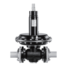
Produit / Prodotto FRM 100065 - 100080
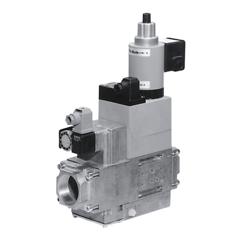
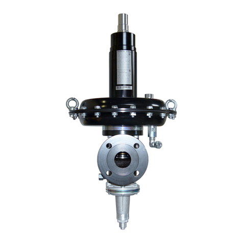
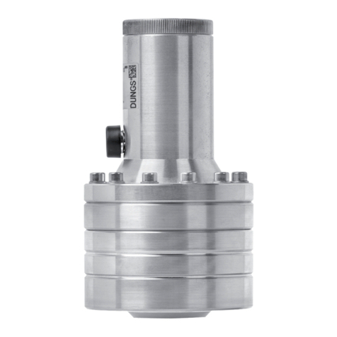
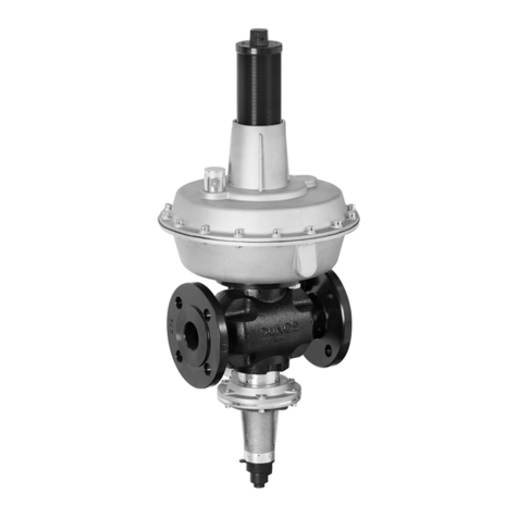
FRM 250065 - 250080 Medium Pressure Regulator 10 bar / 25 bar
Hersteller / Manufacturer
Fabricant / Produttore Karl Dungs GmbH & Co. KG
Karl-Dungs-Platz 1
D-73660 Urbach, Germany
bescheinigt hiermit, dass die in die-
ser Übersicht genannten Produkte
einer EU-Baumusterprüfung un-
terzogen wurden und die wesentli-
chen Sicherheitsanforderungen der:
EU-Druckgeräterichtlinie
2014/68
in der gültigen Fassung erfüllen.
Bei einer von uns nicht freigegebe-
nen Änderung des Gerätes verliert
diese Erklärung ihre Gültigkeit.
certies herewith that the products
named in this overview were sub-
jected to an EU type-examination
and meet the essential safety
requirements:
EU Pressure Equipment Directive
2014/68
as amended.
In the event of an alteration of the
equipment not approved by us this
declaration loses its validity.
certifie par la présente que le
produit mentionné dans cette vue
d'ensemble a été soumis à un
examen de type de l'UE et qu'il
est conforme aux exigences en
matières de sécurité des dernières
versions en vigueur de :
à la directive UE « Équipements
sous pression »
2014/68
Ce communiqué n'est plus valable
si nous eectuons une modication
libre de l'appareil.
Con la presente si certica che i
prodotti citati in questa panoramica
sono stati sottoposti a una prova di
omologazione UE e che i requisiti
di sicurezza essenziali:
direttiva UE sulle attrezzatture
a pressione
2014/68
sono soddisfatti nella versione valida.
In caso di modica dell'apparecchio
non ammessa, questa dichiarazione
perde di validità.
Prüfgrundlage der EU-Baumusterprüfung
Specied requirements of the EU type-examination
Base d'essai de l'examen de type de l'UE
Criteri di prova dell'omologazione UE
DIN EN 334 (01.07.2009)
DIN EN 14382 (01.07.2009)
Gültigkeitsdauer/Bescheinigung
Term of validity/attestation
Validité/certicat
Durata della validità/Attestazione
2024-09-12
CE-0085CP0256
Notizierte Stelle (EU Baumusterprüfung: Modul B)
Notied Body (EU type-examination: Module B)
Organisme notié (Examen de type de l‘UE: module B)
Organismo noticato (Esame UE del tipo: modulo B)
DVGW CERT GmbH
Josef-Wirmer-Straße 1-3
D-53123 Bonn, Germany
Notied Body number: 0085
Überwachung des QM-Systems (Modul D)
Monitoring of the QM system (module D)
Contrôle de la gestion de l‘assurance qualité (module D)
Monitoraggio del sistema QM (modulo D)
DVGW CERT GmbH
Josef-Wirmer-Straße 1-3
D-53123 Bonn, Germany
Notied Body number: 0085
B. Sc., MBA, Simon P. Dungs
Geschäftsführer / Chief Operating Ocer
Directeur / Amministratore
Urbach, 2019-04-01
