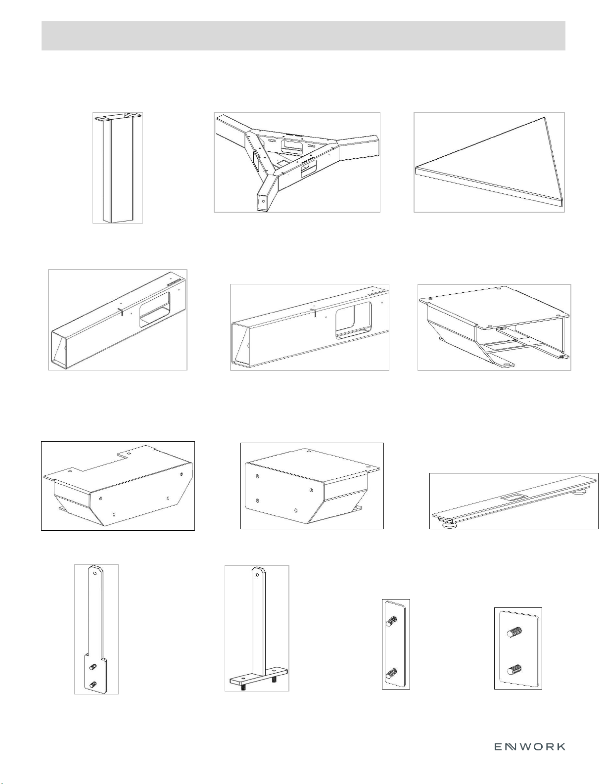
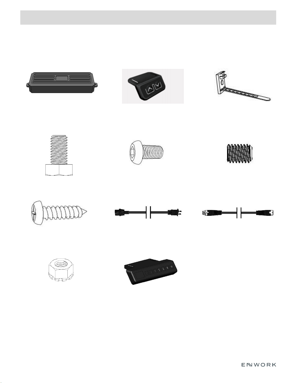
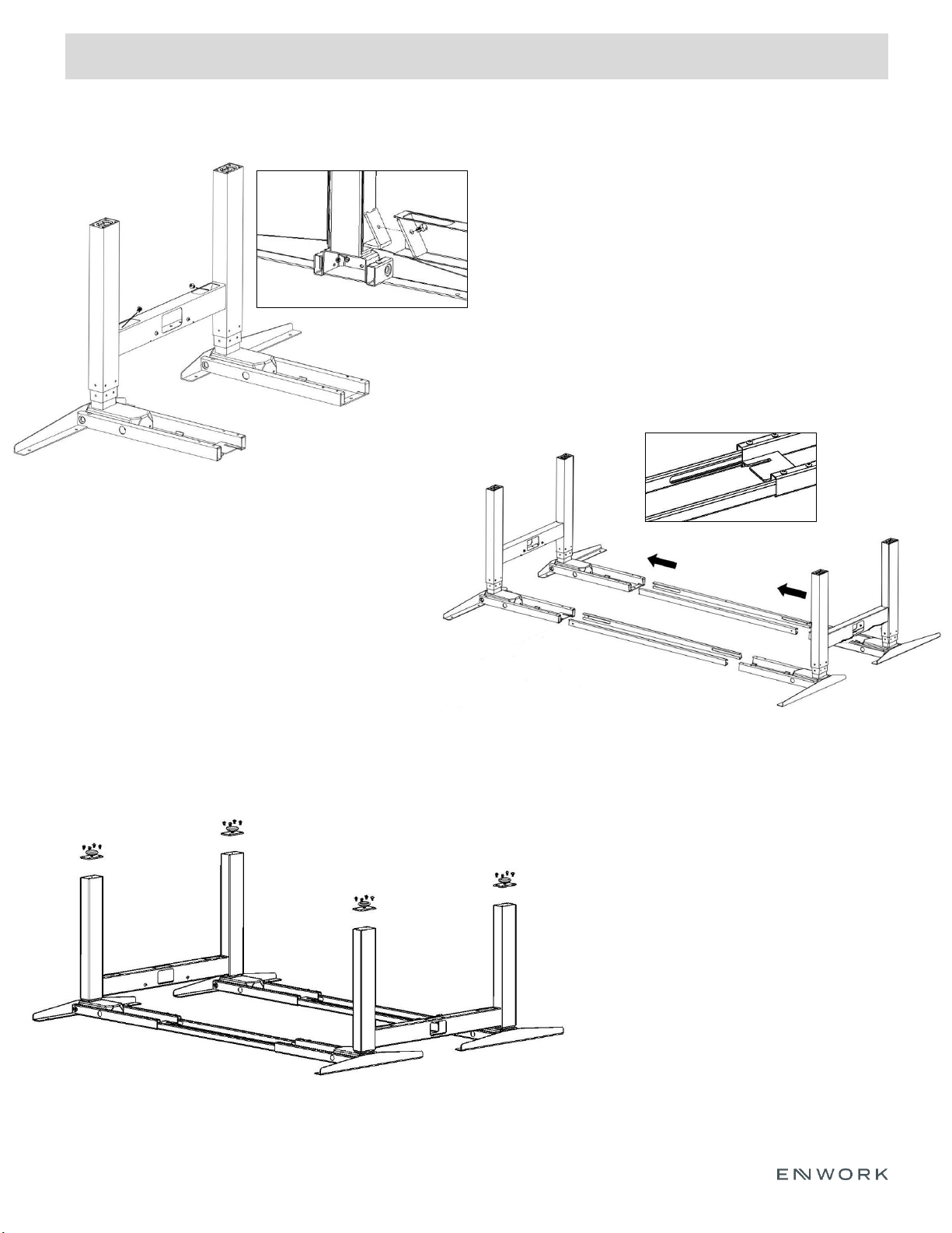
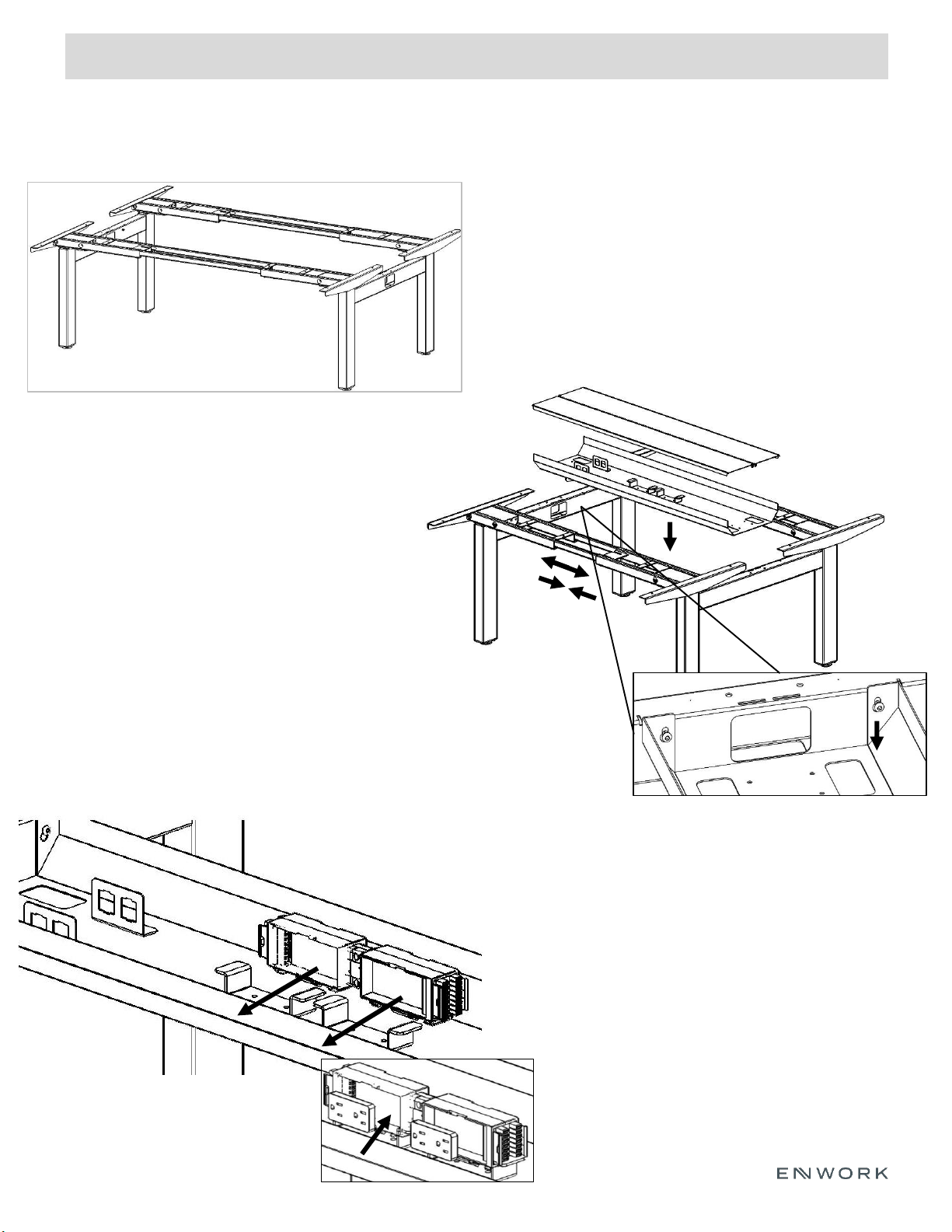
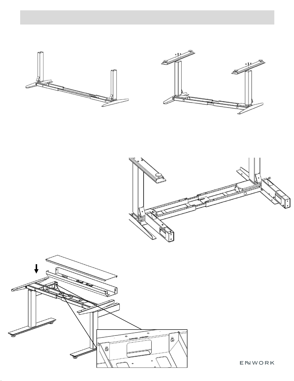
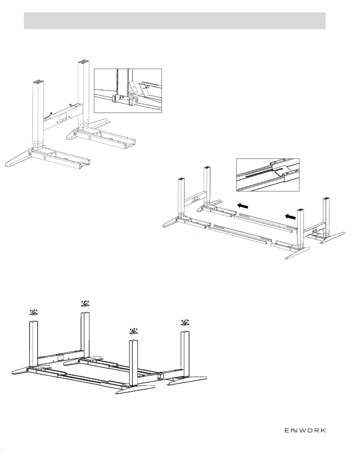
Enwork XTB4 User manual


Other manuals for XTB4
1
Other Enwork Indoor Furnishing manuals

Enwork
Enwork FE Series User manual

Enwork
Enwork TI0023 User manual

Enwork
Enwork ALKALIGN TABLE TI0042 User manual

Enwork
Enwork Concurrence Conference Table User manual

Enwork
Enwork Odyssey User manual

Enwork
Enwork Stealth User manual

Enwork
Enwork Affinity Desk Shell User manual

Enwork
Enwork Equilibrium Round User manual

Enwork
Enwork Cayman CM1001 User manual

Enwork
Enwork TI0022 User manual

Enwork
Enwork Multi-Piece Conference Top User manual

Enwork
Enwork Sensation Flip Table User manual

Enwork
Enwork Concurrence VS User manual

Enwork
Enwork TI0036 User manual

Enwork
Enwork Wall Mounted Tapered Credenza User manual

Enwork
Enwork LANDING XNEL363672-002 User manual

Enwork
Enwork Foundation User manual

Enwork
Enwork AMBITION User manual

Enwork
Enwork eBench Table User manual

Enwork
Enwork Equilibrium User manual


Popular Indoor Furnishing manuals by other brands

Teknion
Teknion interpret CHICAGO POWER MODULE DOUBLE SIDED... installation guide

Coaster
Coaster 4241 Assembly instructions

Trinity
Trinity EcoStorage THA-3328 owner's manual

Mooreco
Mooreco 58229 Assembly instructions

Elkay
Elkay Gourmet Cuisine Centré EGPI4322L Specifications

ofichairs
ofichairs Vortex manual

Original Steifensand
Original Steifensand Seno owner's manual

Triarch
Triarch 31431-35 Assembly instructions

Coaster
Coaster 300525F Assembly instructions

Article
Article NERA Assembly instructions

Allen + Roth
Allen + Roth SERENA PARK LOVESEAT FRS90466 quick start guide

Pacific Casual
Pacific Casual Caspian 14H051SEC-B1 Assembly instructions


