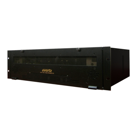
570DSK-12G-F
Keyer With Logo Insertion
Page v
FIGURES
Figure 1-1: 570DSK-12G-F Block Diagram....................................................................................2
Figure 2-1: 570DSK-12G-F Rear and Front Panels .......................................................................4
Figure 2-2: SFP3TR-HDBNC-12G IO Ports Side and Front Views.................................................5
Figure 2-3: IO Ports Configuration .................................................................................................5
Figure 2-4: Video Sources vs Video Output...................................................................................6
Figure 2-5: 570DSK-12G-F card....................................................................................................8
Figure 2-6: Tera Term – Main Menu ..............................................................................................8
Figure 2-7: Tera Term – Network Configuration.............................................................................9
Figure 2-8: Tera Term – Saving New IP ........................................................................................9
Figure 2-9: Command Prompt – FTP to the Device .....................................................................10
Figure 2-10: Command Prompt –Storage Directory Path...........................................................10
Figure 2-11: Tera Term – 4K and HD Directory Location .............................................................10
Figure 2-12: Command Prompt – Storage .json File into the Device............................................10
Figure 2-13: Command Prompt – Storage .rgb File into the Device .............................................11
Figure 2-14: Tera Term – Logo Files Stored in HD Directory ......................................................11
Figure 2-15: .json File Data Content of Static Logo......................................................................12
Figure 2-16: .json File Data Content of Animated Logo................................................................13
Figure 2-17: Output Video Signal with Zoomed Details of the Activated Logo..............................14
Figure 4-1: WebEASY®– Login ...................................................................................................17
Figure 4-2: WebEASY®– Side Menu...........................................................................................18
Figure 4-3: WebEASY®– Top Menu............................................................................................18
Figure 4-4: WebEASY®– Firmware Upgrade...............................................................................19
Figure 4-5: WebEASY®– Unresponsive Message.......................................................................19
Figure 4-6: WebEASY® - Device Status......................................................................................20
Figure 4-7: WebEASY®– Device Config......................................................................................21
Figure 4-8: WebEASY®– PTP Control.........................................................................................23
Figure 4-9: WebEASY®– SFP.....................................................................................................24
Figure 4-10: WebEASY®– Control Interfaces..............................................................................25
Figure 4-11: WebEASY®– Data Interface....................................................................................26
Figure 4-12: WebEASY®– Video Input ........................................................................................26
Figure 4-13: WebEASY®– Video Output .....................................................................................27
Figure 4-14: WebEASY®– Audio Input ........................................................................................27
Figure 4-15: WebEASY®– Audio Output .....................................................................................27
Figure 4-16: WebEASY®– ANC Input..........................................................................................28
Figure 4-17: WebEASY®– ANC Output.......................................................................................28
Figure 4-18: WebEASY®– Host Configuration and IP Routes .....................................................29
Figure 4-19: WebEASY®– GPIO Config......................................................................................29
Figure 4-20: WebEASY®– Traps.................................................................................................30
Figure 5-1: M2100 – Automation Loader exe. file ........................................................................31
Figure 5-2: M2100 – IP Configuration ..........................................................................................32
Figure 5-3: M2100 – Add Keyer Command..................................................................................33
Figure 5-4: M2100 – Activate Keyer Command ...........................................................................34
Figure 5-5: M2100 – Add Transition (from PVW to PGM) Command...........................................35
Figure 5-6: M2100 – Activate Keyer withTransition (from PVW to PGM) Command .................... 36
Figure 5-7: M2100 – Add Command to Display Logo Through PVW ...........................................37
Figure 5-8: M2100 – Activate Command to Display Logo Through PVW .....................................38
Figure 5-9: M2100 – Add Command to Display Logo Through All Outputs ..................................39
Figure 5-10: M2100 – Add Command to Display Logo Through All Outputs ................................40
Figure 5-11: M2100 – Add Command to Remove Logo Through PVW........................................41
