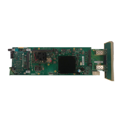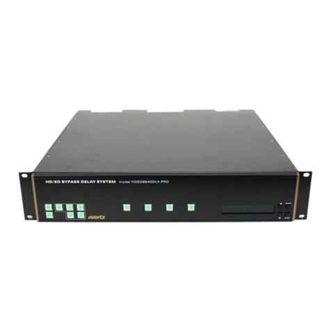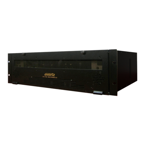
Model 9540 Video Delay Processor Manual
4. TECHNICAL DESCRIPTION.......................................................................................................... 4-1
4.1. SPECIFICATIONS.......................................................................................................................... 4-1
4.1.1. Serial Video Input.................................................................................................................4-1
4.1.2. Serial Video Outputs............................................................................................................4-1
4.1.3. Electrical...............................................................................................................................4-1
4.1.4. Functional.............................................................................................................................4-1
4.2. UPDATING THE FIRMWARE IN THE VIDEO DELAY PROCESSOR .......................................... 4-2
4.2.1. Requirements.......................................................................................................................4-2
4.2.2. Update Procedure................................................................................................................4-2
4.2.2.1. Part I – Terminal program Setup.............................................................................4-2
4.2.2.2. Part II – Invoke upload mode via the front panel ....................................................4-2
4.2.2.3. Part III – Invoke upload mode from the Terminal Program.....................................4-3
4.2.2.4. Part IV – Uploading the new firmware ....................................................................4-4
4.2.2.5. Part V – Completing the Upgrade...........................................................................4-4
Figures
Figure 1-1: 9540 Block Diagram......................................................................................................1-2
Figure 2-1: Model 9540 Rear Panel Layout.....................................................................................2-1
Figure 2-2: General Purpose I/O Schematic....................................................................................2-4
Figure 2-3: Powering the General Purpose Input Opto Isolators from the Unit ...............................2-5
Figure 2-4: Powering the General Purpose Input Opto Isolators from an External Power Supply ..2-5
Figure 2-5: Powering the General Purpose Output Opto Isolators from the Unit.............................2-6
Figure 2-6: Power the General Purpose Output Opto Isolators from an External Power Supply ....2-6
Figure 3-1: Front Panel Layout........................................................................................................3-1
Figure 3-2: Overview of the Setup Menu.........................................................................................3-4
Figure 3-3: Overview of the Video Delay Menu...............................................................................3-5
Figure 3-4: Overview of the Vertical Blanking Menu........................................................................3-7
Tables
Table 2-1: COM 1 Connector Pin Definitions...................................................................................2-1
Table 2-2: GPIO Connector Pin Definitions.....................................................................................2-2
Table 3-1: Model 9540 Video Delay Units – 525 and 625 Line Video .............................................3-6
Table 3-2: Model 9542 Video Delay Units – 525 and 625 Line Video .............................................3-6
Table 3-3: Typical Video Delay Settings – 525 and 625 Line Video................................................3-7
ii Revision 1.2 TABLE OF CONTENTS
