Evolis AGILIA User manual

Service-Manual_Agilia_R02_ENG_20231023-A 1
AGILIA
SERVICE MANUAL

Service-Manual_Agilia_R02_ENG_20231023-A 2
INTRODUCTION ............................................................................................................................................................................................................6
Proprietary Notice....................................................................................................................................................................................................6
Trademark Acknowledgments.........................................................................................................................................................................6
Environmental information – recycling of end-of-life products....................................................................................................6
Operator ........................................................................................................................................................................................................................7
Mechanical Maintenance personnel:............................................................................................................................................................7
Electrical Maintenance personnel:.................................................................................................................................................................7
Symbols......................................................................................................................................................................................................................... 8
Safety...............................................................................................................................................................................................................................9
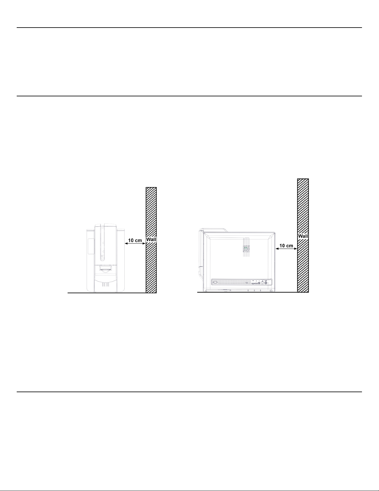
Safe Environment.....................................................................................................................................................................................................9
Safe Human Interface............................................................................................................................................................................................9
General Safety Regulations ..............................................................................................................................................................................10
DESCRIPTION OF THE PRINTER.........................................................................................................................................................................11
IMAGE PRINTING PROCESS................................................................................................................................................................................. 13
Printing process...........................................................................................................................................................13
Retransfer process ......................................................................................................................................................14
Feeding & Transport process ..................................................................................................................................15
Magnetic position........................................................................................................................................................16
Smart contact position..............................................................................................................................................16
Contactless position ...................................................................................................................................................16
EXPLODED VIEW.......................................................................................................................................................................................................17
SENSORS - DRAWINGS..........................................................................................................................................................................................24
MOTORS - DRAWINGS ...........................................................................................................................................................................................28
FANS - DRAWINGS....................................................................................................................................................................................................31
SPARE PARTS LIST ................................................................................................................................................................................................... 33
PARTS REPLACEMENT RECOMMENDATION............................................................................................................................................ 35
REPLACEMENT PROCEDURES .........................................................................................................................................................................36
TECHNIQUE TO AVOID DAMAGING TAPS ..................................................................................................................................................37
CASSETTES HANDLING .........................................................................................................................................................................................38
LOCKING SYSTEM.....................................................................................................................................................................................................39
Tools required .............................................................................................................................................................................................................62
Step 1 – DUST FILTER – CP012725 .................................................................................................................................................................63
Step 2 – CLEAR FILM CASSETTE – S10439................................................................................................................................................64
Step 3 – COLOR RIBBON CASSETTE – S10440.......................................................................................................................................66
Step 4 – LCD (TOUCH SCREEN LCD DISPLAY) - S10446..................................................................................................................68
Step 5 – ENCLOSURE: FRONT DOOR - SE011234.................................................................................................................................. 72
Step 6 - ENCLOSURE: REAR COVER - SE010856.................................................................................................................................. 73
Step 7 - ENCLOSURE: REAR RIGHT COVER - CI012690 ....................................................................................................................76

Service-Manual_Agilia_R02_ENG_20231023-A 3
Step 8 - ENCLOSURE: FRONT RIGHT COVER - CI013150..................................................................................................................79
Step 9 - ENCLOSURE: COVER - CI012830.................................................................................................................................................82
Step 10 - ENCLOSURE: LEFT COVER - CI012829 ...................................................................................................................................86
Step 11 - FRONT OUTPUT TRAY - S10450 ..................................................................................................................................................87
Step 12 – COMPLETE FEEDER – S10441 .....................................................................................................................................................88
Step 13 – MAIN BOARD – S10443................................................................................................................................................................... 92
Step 14 - COMPLETE HEATING ROLLER - S10442 ...............................................................................................................................94
Step 15 - PRINT HEAD – S10445 ...................................................................................................................................................................100
Step 16 – S12 (FRONT DOOR SENSOR) - CP011382............................................................................................................................. 105
Step 17 – S10 (FLIP: ROTATION SENSOR) – S10455 ............................................................................................................................106
Step 18 – S11 (FLIP: PRESENCE CARD SENSOR) – S10455 ..............................................................................................................107
Step 19- S8 (COLOR RIBBON BRAKE ROTATION SENSOR) – S10455......................................................................................108
Step 20 – S4 (RIBBON: TRANSMITTER SENSOR) – S10452............................................................................................................109
Step 21 – S5 (RIBBON: RECEIVER SENSOR) – S10451......................................................................................................................... 112
Step 22 – S3 (CLEAR FILM SYNCHRONIZATION SENSOR) - CP012210 .....................................................................................113
Step 23 – S6 (CLEAR FILM DETECTION SENSOR) – CP012210 ...................................................................................................... 114
Step 24 – S14 (MAGNETIC SYNCHRONIZATION SENSOR) – CP012210 .................................................................................... 117
Step 25 – S9 (SYNCHRONIZATION CARD SENSOR) – CP011382................................................................................................. 120
Step 26 – S15 (CARD EXIT SENSOR) – CP011382 ................................................................................................................................... 121
Step 27 – S13 (CLEAR FILM PULLING ROTATION SENSOR) – S10455 .......................................................................................122
Step 28 – J2 (FEEDER ALMOST EMPTY SENSOR) - CP011452 ..................................................................................................... 124
Step 29 – J3 (FEEDER EMPTY SENSOR) – S10455 ...............................................................................................................................125
Step 30 – J4 (FEEDER MANUAL SENSOR) – CP011382 .................................................................................................................... 129
Step 31 – OPT3 (REJECT BOX COVER OPEN SENSOR) – CP012739............................................................................................131
Step 32 – OPT2 (REJECT BOX FULL SENSOR) – CP012739.............................................................................................................132
Step 33 – OPT1 (FEEDER DOOR SENSOR) – CP012739.....................................................................................................................133
Step 34 – J6 (FEEDER MOTOR) – CP011427........................................................................................................................................... 134
Step 35 – J7 (MANUAL FEEDER MOTOR) – CP011512 ........................................................................................................................135
Step 36 - M3 (FLIP: CARD TRANSPORT MOTOR) – S10098........................................................................................................... 138
Step 37 – M4 (FLIP: ROTATION MOTOR) – S10098 ............................................................................................................................ 139
Step 38 – FLIP OVER – S10454 / PUSHER BLADE - CP010175......................................................................................................140
Step 39 – NBR ROLLER – CP011223 / GEAR CLIP Z44-M0,5-D4 – CP009016 ....................................................................... 145
Step 40 – ROLLER: CLEANING – S10122 ................................................................................................................................................... 147
Step 41 – M5 (BRAKE COLOR RIBBON MOTOR) - S10453..............................................................................................................149
Step 42 – M8 (PULL CLEAR RIBBON MOTOR) – S10453.................................................................................................................. 151
Step 43 – R1 (COLOR RIBBON: RFID CARD) – S10456...................................................................................................................... 154
Step 44 – R2 (CLEAR FILM: RFID CARD) – S10456 ..............................................................................................................................155
Step 45 - REMOTE CONNECTIVITY CARD – S10457.......................................................................................................................... 158
Step 46 – F5-F6-DOUBLE FAN – S10448................................................................................................................................................. 165

Service-Manual_Agilia_R02_ENG_20231023-A 4
Step 47 – F1 (HEAT ROLLER FAN) - S10448 ........................................................................................................................................... 169
Step 48 – F2 (PRINT HEAD FAN) - S10448 .............................................................................................................................................174
Step 49 - F7 (EXTERIOR HEAD FAN) - S10448..................................................................................................................................... 177
Step 50 - M2 (PRINT HEAD MOTOR) - S10453...................................................................................................................................... 178
Step 51 – S7 (PRINT HEAD: CAME SENSOR) – S10455 ....................................................................................................................... 181
Step 52 - M1 (HEAT ROLLER MOTOR) - S10453....................................................................................................................................184
Step 53 – S1 (HEAT ROLLER CAME SENSOR) – S10455.................................................................................................................... 187
Step 54 - PRINT HEAD ROLLER – S10449............................................................................................................................................... 192
Step 55 – INFERIOR HEAT ROLLER – CP012602.................................................................................................................................. 198
Step 56 – OPTION ROLLER – CP012603................................................................................................................................................... 201
CLEANING PROCEDURES................................................................................................................................................................................. 205
Regular Cleaning................................................................................................................................................................................................206
Cleaning the cassettes ............................................................................................................................................207
Cleaning the print head..........................................................................................................................................209
Cleaning the printer .................................................................................................................................................209
Advanced cleaning............................................................................................................................................................................................. 210
Cleaning the cassettes ............................................................................................................................................211
Cleaning the print head..........................................................................................................................................213
Cleaning the printer .................................................................................................................................................213
Specific cleaning...................................................................................................................................................................................................215
Cleaning the print head roller...............................................................................................................................215
Cleaning the dust filter............................................................................................................................................216
Manual Cleaning.................................................................................................................................................................................................. 217
Cleaning the feeder ..................................................................................................................................................218
Cleaning the print head roller...............................................................................................................................220
Cleaning the transport roller.................................................................................................................................220
Cleaning the option roller ......................................................................................................................................221
Cleaning the inferior heat roller...........................................................................................................................221
Clean the flip over rollers........................................................................................................................................222
Cleaning the Cleaning Roller........................................................................................................................................................................223
COMMUNICATION with the printer..............................................................................................................................................................225
Installing Evolis Premium Suite 2 ..............................................................................................................................................................225
How to Communicate with the Printer through the Evolis Premium Suite.....................................................................226
Updating the Firmware for Windows..................................................................................................................................................... 228
SENSORS................................................................................................................................................................................................................. 230
Commands for Adjusting Sensors.............................................................................................................................................................232
Commands to read the value of the sensors ......................................................................................................................................233
MOTORS................................................................................................................................................................................................................... 234

Service-Manual_Agilia_R02_ENG_20231023-A 5
Commands to move motors.........................................................................................................................................................................236
FANS ...........................................................................................................................................................................................................................237
Commands to launch fans.............................................................................................................................................................................237
Printer Commands............................................................................................................................................................................................ 238
How to Print a Test Card .................................................................................................................................................................................239
Printing a technical test card................................................................................................................................239
Printing a graphical test card ...............................................................................................................................239
DESCRIPTION OF THE PORTS ON THE MAIN BOARD ..................................................................................................................240
DESCRIPTION OF THE PORTS ON THE REMOTE CONNECTIVITY CARD............................................................................. 241
DESCRIPTION OF THE PORTS ON THE FEEDER BOARD ............................................................................................................ 242
PRINTING ADJUSTMENT.................................................................................................................................................................................... 243
X: Print Position Adjustment.................................................................................................................................243
Y: Print Position Adjustment.................................................................................................................................243
Retransfer adjustment ............................................................................................................................................244
TROUBLESHOOTING............................................................................................................................................................................................ 245
Printing problems.............................................................................................................................................................................................. 246
No Printing...................................................................................................................................................................246
Poor quality..................................................................................................................................................................247
Tilted printing .............................................................................................................................................................248
Problems Loading Cards................................................................................................................................................................................ 250
Jammed card........................................................................................................................................................................................................ 250
Color shift: Cleaning.......................................................................................................................................................................................... 250
Missing printing: White line(s) on the prints ........................................................................................................................................251
COLORED WRINKLES ........................................................................................................................................................................................251
CLEAR WRINKLES...............................................................................................................................................................................................252
FIND TECHNICAL INFORMATION ONLINE ...............................................................................................................................................253

Service-Manual_Agilia_R02_ENG_20231023-A 6
INTRODUCTION
Liability Statement
This product has been built to the high standards of EVOLIS. Please do not attempt to operate or repair this
equipment without adequate training. Any use, operation, or repair in contravention of this document is at
your own risk. By acceptance of this system you hereby assume all liability consequent to your use or misuse
of this equipment. Evolis assumes no liability for incidental, special, or consequential damage of any kind.
Equipment specifications, applications, and options are subject to change at the sole discretion of Evolis
without notice.
Proprietary Notice
All drawings and information herein are the property of Evolis. All unauthorized use and reproduction are
prohibited.
Trademark Acknowledgments
Printer is trademark of Evolis Card Printer
Microsoft Windows, Windows Embedded, are registered or trademarks of Microsoft Corporation In the United
States or other countries.
Atom ® is a registered trademark of Intel Inc.
TrueType is a registered trademark of Apple Inc.
The information contained in this present document is subject to change without prior notice. All product or
program names mentioned in this document are registered trademarks owned by the respective companies.
They are only used in this document for editorial purposes.
Environmental information – recycling of end-of-life products
Evolis is committed to helping the environment by reducing the energy consumption of its products. The
manufacture of the equipment that you have purchased required the extraction and use of natural resources.
It may contain materials that are hazardous to health and the environment. To prevent the dispersal of such
materials into our environment and reduce the pressure on our natural resources, we recommend that you
use existing collection systems.
The crossed-out dustbin symbol on your device is a reminder to use these systems.
If you need further information on collection, re-use and recycling systems, contact your local or regional waste
management body.

Service-Manual_Agilia_R02_ENG_20231023-A 7
This manual describes the disassembly operation and troubleshooting of Evolis printer.
Personnel assigned to operating the machine, in addition to being professionally trained for their specific job
must read the manuals, pay careful attention to safety regulations and the sections pertinent to their job.
Individuals assigned to operating the machine are broken down as follows:
Operator
Assigned to loading the elements to process, visual inspection of the work cycle, unloading of finished product
and cleaning of the machine.
Mechanical Maintenance personnel:
Assigned to mechanical maintenance of the machine.
Electrical Maintenance personnel:
Assigned to electrical maintenance of the machine.
EVOLIS shall not be held responsible for any non-conforming use of equipment of its manufacture.

Service-Manual_Agilia_R02_ENG_20231023-A 8
Symbols
The symbols used in this manual along with their meaning are shown below. The symbols are repeated within
the chapters and/or sections and have the following meaning:
Generic warning:
This symbol indicates the need to read the manual carefully or the necessity of an important
maneuver or maintenance operation.
Electricity warning:
This symbol indicates dangerous voltage associated with the powerful enough to constitute an
electrical risk. This symbol may also appear on the machine at the risk area.
Temperature warning:
This symbol indicates high temperature associated to some components. Wait the module to cool
down completely before removing some component. This symbol may also appear on the machine
at the risk area.

Service-Manual_Agilia_R02_ENG_20231023-A 9
Safety
The following basic safety tips are given to ensure safe installation, operation, and maintenance of EVOLIS
equipment and are not to be considered as comprehensive on matters of safety. The tests performed
demonstrate the safety and reliability of heating components when used correctly. It is necessary that the
operator be informed of precautionary regulations aimed at avoiding injury or damage to the equipment.
Safe Environment
•Connect equipment to a grounded facility power source. Do not defeat or bypass the ground lead.
•Place the equipment on a stable surface and ensure that the floors in the work area are dry and non-
slip. Insulated rubber floor mats are preferred.
•Install the printer where the airflow is not obstructed to ensure the proper function of the fans and
cooling of the printer.
•Avoid putting rear and left sides of the printer against a wall or any solid surfaces.
•Leave at least 10cm between a solid surface and the rear and left sides of the printer.
•Know the location of equipment branch circuit interrupters or circuit breakers and how to turn them
on and off in case of emergency.
•Know the location of fire extinguishers and how to use them. Use only ABC type extinguishers on
electrical fires.
•Know local procedures for first aid and emergency assistance at the customer facility.
•Use adequate lighting at the equipment.
•Maintain the recommended range of temperature and humidity in equipment area.
•Do not use this product in an environment containing volatile or flammable compounds.
Safe Human Interface
•Use proper lifting techniques when moving or installing the equipment.
•Use standard electrostatic discharge (ESD) precautions when working on or near electrical circuits.
•Do not defeat or disconnect safety interlocks on covers.

Service-Manual_Agilia_R02_ENG_20231023-A 10
General Safety Regulations
The User must comply with the regulations and work in the best possible safety conditions to prevent
decreasing the degree of machine safety. Therefore, it is necessary to develop a Standard Operating Procedure
(S.O.P.) related to maneuvers to effect for turning on and off the equipment. This procedure, which shall be
prepared around the time of installation, shall serve as a reference for the Operator and shall be written in
his/her language.
Training is essential and must include:
Familiarization with system operating procedures.
Understanding of the necessity for Individual Protection Devices (I.P.D.)
It is advisable not to change the intended use without previously contacting the Manufacturer.
An additional risk may be represented by fire caused by processing materials other than those the equipment
is designed for.
Do not subject materials other than those the equipment was designed for.
The most serious collateral risk associated, which may be fatal, is electricity.
This may occur when the manufacturer’s warning and procedures are not followed. Unauthorized and
untrained personnel must never do any work on the electrical part. The safety devices must never be removed,
and their operation must be periodically checked.
Do not work on the electrical part if you are not trained to do so. Do not remove protection devices.
This product is highly sensitive to electrostatic discharge (ESD), and the best way to avoid ESD is to
use a wrist strap, grounding mat or table.

Service-Manual_Agilia_R02_ENG_20231023-A 11
DESCRIPTION OF THE PRINTER
A. Card feeder
B. Manual card feeder (insertion / ejection)
C. Front output tray
D. Power cable connector
E. Ethernet connector
F. USB socket (type A)
G. USB socket (type B)
H. HDMI connector
I. Location for the Kensington locking system
J. Rear output box
K. Side panel opening mechanism
L. Power button
M. LCD Touchscreen
N. Card thickness selector

Service-Manual_Agilia_R02_ENG_20231023-A 12
O. Rear output
P. Location for the infra-red kit
Q. Jam-clearing wheel
R. Dust filter
S. Heating roller
T. Print head
U. Cassette for the color ribbon
V. Cassette for the clear film

Service-Manual_Agilia_R02_ENG_20231023-A 13
IMAGE PRINTING PROCESS
Printing process
Diameter measurement:
•Step and DC on Clear side
•Step on Color side (DC deducted from Step)
•Clear Backward and Color Forward printing
•Printing speed: 50mm/s *
•Peel-off speed: 100 mm/s *
•Trigger printing on black mark
•Print size adjustable in X and Y directions
•Color panel shifting not currently configurable
•Clear film is master during printing, color ribbon is not under tension.
•On both DC motors, the film is "free" during printing.

Service-Manual_Agilia_R02_ENG_20231023-A 14
Retransfer process
•Clear Forward lamination
•Laminating speed: 25 mm/s *
•Film position in retransfer position defines X image positioning
•Card retransfer position is fixed
•Profiles according to the card (material / thickness)
•Adjustable temperature and speed parameters
•Adjustable heat retention times
•Movable axis mechanically linked to the KRC and supported by two rollers at the card ends.

Service-Manual_Agilia_R02_ENG_20231023-A 15
Feeding & Transport process
1. Cards are inserted either via the feeder or the
manual feeder.
2. The card is transferred to the flip over.
3. The card is positioned under the heating
roller to be retransferred.
4. The printed card is ejected.
[1]
[1]

Service-Manual_Agilia_R02_ENG_20231023-A 16
Magnetic position
Smart contact position
Contactless position

Service-Manual_Agilia_R02_ENG_20231023-A 17
EXPLODED VIEW
Drawing 1

Service-Manual_Agilia_R02_ENG_20231023-A 18
Drawing 2

Service-Manual_Agilia_R02_ENG_20231023-A 19
Drawing 3

Service-Manual_Agilia_R02_ENG_20231023-A 20
Drawing 4
Table of contents
Other Evolis Printer manuals

Evolis
Evolis tattoo rw User manual

Evolis
Evolis Dualys 3 User manual

Evolis
Evolis Pebble Operator's manual

Evolis
Evolis Primacy User manual

Evolis
Evolis Pebble User manual

Evolis
Evolis Tattoo User manual

Evolis
Evolis Tattoo Operator's manual

Evolis
Evolis PRIMACY 2 User manual

Evolis
Evolis Badgy User manual

Evolis
Evolis New Pebble User manual

Evolis
Evolis A5405 User manual

Evolis
Evolis KC PRIME User manual

Evolis
Evolis Zenius Use and care manual

Evolis
Evolis PRIMACY 2 User manual

Evolis
Evolis Tattoo 2 User manual

Evolis
Evolis TattooRW User manual

Evolis
Evolis Primacy User manual

Evolis
Evolis KM500B User manual

Evolis
Evolis QUANTUM User manual

Evolis
Evolis Dualys User manual