manuals.online logo
Brands
  1. Home
  2. •
  3. Brands
  4. •
  5. FabiaTech
  6. •
  7. Computer Hardware
  8. •
  9. FabiaTech FB2505 Series User instructions

FabiaTech FB2505 Series User instructions

Version 1.1 FB2505 Series User’s Quick Setting Page 1/3
www.fabiatech.com ©2007-2008 FabiaTech Corporation
1. Brief
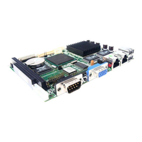
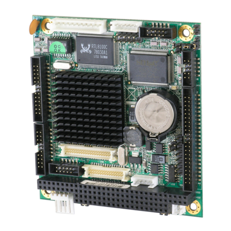
The FB2505 is a Low power AMD LX, all in one, half-size CPU card. This user’s quick setting provides
the jumper and switch settings, connector location, and their pin assignment.
2. Board Placement
CN10
CN12
JP1 CN1 CN2 CN3
LED2
LED1 CN4 CN7
CN5 J2 CN6 CN8 CN9
JP2
LED3
CN11
CN13
DB2
CN16
DB1
CN15J1
CN14
BUS1
CPU
BT1
BZ1
JP3
J3
JP5
JP4
CN17
DIMM1
3. Packing List
1 FB2505 all-in-one CPU board.
1 40-pin hard disk drive interface cable and 1 34-pin floppy drive interface cable.
1 serial port and parallel port interface cable with bracket.
1 PS/2 keyboard and mouse port adapter cable. (Optional)
1 USB cable, 1 Audio cable, and 1 FB4641x Audio adapter board. (All are optional items)
1 compact disc includes software utilities and manuals.
4. Features
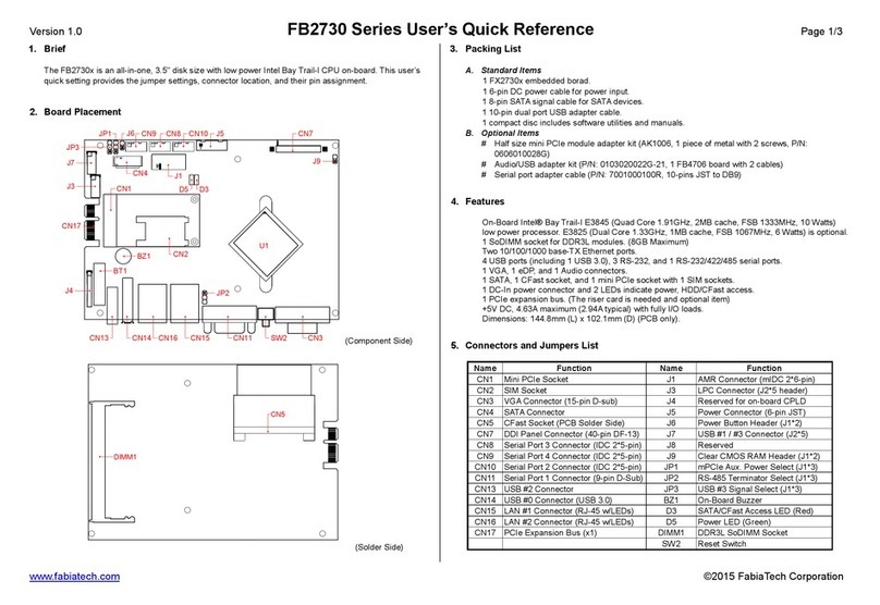
* On-board AMD LX-800 CPU (running at 500MHz) with heat sink only. (Fanless operation)
* Compact size slot card with ISAand PC/104 bus.
* AMD Geode CS5536 chipset with UMA architecture.
* Support 16-bit ISA bus, but without DMA transfer function.
* On-board 128MB DDR and 1 SoDIMM socket (FB2505A only) for up to 1152MB maximum.
* 2 USB ports, 10/100M-TX Ethernet with RJ-45 connector.
* Supports CRT and LCD (FB2505A only) with up to 254MB shared memory.
* 1 floppy, 1 PCI IDE, 1 parallel, 1 RS-232 and 1 RS-232/422/485 ports.
* CompactFlash socket for 3.3V CompactFlash and MicroDrives.
* PS/2 keyboard and mouse interface, 4-bit TTL I/O, On-board buzzer, and LED indicators.
* Software programmable watchdog timer and Flash BIOS with easy upgrade utility.
* Provides 1 AC97 connector for Audio functions. (FB2505Aonly)
* Compact size, 185 mm x 122 mm.
5. Connectors and Jumpers List
Name Function Name Function
CN1 44-pin IDE Connector (Reserved) J1 Reserved
CN2 40-pin IDE Connector (40-pin IDC) J2 Reset and LED Indicator Header (J2*3)
CN3 Floppy Connector (34-pin IDC) J3 Reserved
CN4 LCD Connector (40-pin DF13) DB1 CRT Connector (15-pin D-sub)
CN5 LCD Power Connector (5-pin JST) DB2 COM1 Connector (9-pin D-sub)
CN6 TTL I/O Connector (5-pin JST) DIMM1 SoDIMM Socket (200-pin)
CN7 AC97 Connector (12-pin IDC) BUS1 PC/104 Connector (64 and 40 pin)
CN8 Parallel Port Connector (26-pin IDC) BUS2 ISA Golden Finger (16-bit)
CN9 COM2 Connector (10-pin IDC) BUS3 ISA Golden Finger (8-bit)
CN10 SATA#1 Connector (Reserved) JP1 CF Master/Slave Select Jumper (J1*3)
CN11 USB Connector (J2*5) JP2 485 Terminator Resister Select (J1*3)
CN12 SATA#0 Connector (Reserved) JP3 SRAM Mapping Select (J1*3)
CN13 LAN Connector (RJ45 w/LEDs) JP4 COM2 Mode Select (J2*3)
CN14 Aux. Power Connector (6-pin JST) JP5 CMOS RAM Select (J1*3)
CN15 KB/MS Connector (6-pin JST) LED1 SATAAccess LED (Reserved)
CN16 KB/MS Connector (6-pin mini-Din) LED2 IDE Access LED (Red, Reserved)
CN17 CompactFlash Socket (50-pin) LED3 On-Board Power/WD LED (Green)
BZ1 On-board Buzzer D4 Reserved LED Indicator
Version 1.1 FB2505 Series User’s Quick Setting Page 2/3
www.fabiatech.com ©2007-2008 FabiaTech Corporation
6. Connectors and Their Relative Jumpers
A. Reset and LED Indicator Header (J2)
B. Keyboard and Mouse Connector (CN15 and CN16)
CN16 is a standard PS/2 type keyboard connector and any PS/2 type keyboard can plug into CN16
directly without extra adapter cable. CN15 provides PS/2 mouse interface, use optional mouse
adapter cable to connect between CN15 and standard PS/2 mouse.
C. Auxiliary Power Connector and Power/WD LED (CN14, LED3, and J2)
D. Floppy Connector (CN3: 34-pin 2.54mm IDC)
Note that the included floppy cable supports only 720KB, 1.44MB, and 2.88MB disk drives.
E. Hard Disk Connectors and LED Indicators (CN1, CN2, CN10, CN12, J2, LED1, and LED2)
Use the included 40-pin hard disk cable, you can attach up to two 3.5” hard disk drives with CN2
connector. CN1, CN10, CN12 connectors and LED1, LED2 are all reserved. FB2505 series only
provides pin 3 & 4 of J2 header for connecting external IDE LED.
F. Parallel Port Connector (CN8: 26-pin 2.0mm IDC)
The included printer interface cable is used to transfer 26-pin connector into standard parallel port
connector (D-sub 25-pin).
G. SoDIMM Socket (DIMM1, FB2505A only)
DIMM1 supports 200-pin DDR-333/400 RAM with size of 1128MB, 256MB, 512MB, and 1GB.
H. Serial Port Connectors & Selector (DB2, CN9, JP2, and JP4)
There are 2 connectors and 2 jumpers that served for on-board 2 serial ports. The following table
and figure list the combination and pin definition of them:
Functional connector, header,
and jumper of serial ports Serial Port 1 Serial Port 2
RS-232 Signals DB2 CN9 and JP4
RS-422 Signals - CN9, JP2, and JP4
RS-485 Signals - CN9, JP2, and JP4
Terminator for RS-422/RS-485 - JP2
I. CRT Connector (DB1)
J. LCD Connectors (CN4 and CN5, FB2505A only)
CN4 supports 24-bit TTL LCD signals, and CN5 is the power connector for inverter board. Please
refer the pin assignment as following table and figure.
Pin 1: Red
Pin 2: Green
Pin 3: Blue
Pin 13: Hsync
Pin 14: Vsync
Pin 12: DDC Data
Pin 15: DDC Clock
Pin 5 & 10: Digital Ground
Pin 6,7,8: Analog Ground
Others: Not Used
15
DB1 (D-sub 15)
11
15
5 1
26
J2
J2 Function J2 Function
1 PWR/WD LED+ 2 PWR/WD LED-
3 IDE Access LED+ 4 IDE Access LED-
5 Ground 6 Reset
CN14 Pin 1:Ground
Pin 2:+5V
Pin 3:+5V
Pin 4:Ground
Pin 5:Ground
Pin 6:+12V
61
Note: CN14 is ideal for standalone applications. LED3 is
on-board power/watchdog LED and pin 1 & 2 of J2
provide header for external LEDs. 5
1
RS-232 RS-485
(
Half Du
p
lex
)
Reserved
Factor
y
Preset
2
65
1
5
1
5
1
2
6
2
6
2
6
RS-422
(
Full Du
p
lex
)
JP4 JP4
JP4 JP4
Off
JP2: Terminator Resister Select
Factory Preset ON
DB2
(D-sub 9)
DB2 Signals CN9 D-sub 9 RS-232 RS-422 RS-485
1 -DCD1 1 1 -DCD2 -
6 -DSR1 2 6 -DSR2 -
2 RXD1 3 2 RXD2 RX- 485-
7 -RTS1 4 7 -RTS2 TX- -
3 TXD1 5 3 TXD2 RX+ 485+
8 -CTS1 6 8 -CTS2 TX+ -
4 -DTR1 7 4 -DTR2 -
9 -RI1 8 9 -RI2 -
5 Ground1 9 5 Ground2
Metal Case Ground 10 Metal Case Ground
1
5 9
6
1 2 3
123
Pin 1: Mouse Data
Pin 2: Keyboard Data
Pin 3: Ground
Pin 4: VCC
Pin 5: Mouse Clock
Pin 6: Keyboard Clock
6
1
CN15 Note that CN15 and CN16 all support PS/2
keyboard and mouse signals and have to
order 3-head cable from your supplier.
Version 1.1 FB2505 Series User’s Quick Setting Page 3/3
www.fabiatech.com ©2007-2008 FabiaTech Corporation
K. LAN Connector and LED Indicators (CN13: RJ45)
CN13 is a RJ45 connector with 2 LEDs. The up side LED (orange) indicates data is accessing and
the down side LED (green) indicates on-line status. (When lighted indicates on-line and off indicates
off-line) The following lists the pin assignment of CN13:
L. USB and Audio Connectors (CN11 and CN7), and Connectors on FB4641x Adapter Board
CN11 supports 2 port USB signals and CN7 provides AC97 signals for Audio function. Use the
FB4641x (USB and Audio Adapter Board) and cables for your USB and Audio applications.
M. TTL I/O Connector (CN6: 5-pin 2.0mm JST)
N. CompactFlash Socket and Master/Slave Select (CN17 and JP1)
The CompactFlash socket CN17 (on the solder side) supports 3.3V CompactFlash and MicroDrives.
JP1 is used to select master/slave device of this socket. Be sure to avoid the same master/slave
setting with which connects to 44-pin IDE (CN1) connector, if CN17 and CN1(if existed) are used
simultaneously.
O. CMOS RAM Select Jumper (JP5)
P. SARM Memory Mapping Address Select Jumper (JP3, Reserved)
Q. PC/104 Connectors (BUS1: 64-pin IDC & 40-pin IDC)
1
2
3
1
2
3
JP5
Normal O
p
eration
Factor
y
Preset
JP5
Clear CMOS RAM
End of Document
18
CN13
(
Front View
)
CN13 Signal CN13 Signal
1 TPTX+ 5 FBG1
2 TPTX- 6 TPRX-
3 TPRX+ 7 FBG2
4 FBG1 8 FBG2
CN5
15
Pin 1: +12V
Pin 2: Ground
Pin 3: ENVDD
Pin 4: N.C.
Pin 5:
+
5V
Note: If any question when connecting FB2505A
with LCD panels, you could contact technical
support division of FabiaTech Corporation.
CN4 Signal CN4 Signal CN4 Signal CN4 Signal
1 +5V 21 FP12 2 +5V 22 FP13
3 Ground 23 FP14 4 Ground 24 FP15
5 +3.3V 25 FP16 6 +3.3V 26 FP17
7 N.C. 27 FP18 8 Ground 28 FP19
9 FP0 29 FP20 10 FP1 30 FP21
11 FP2 31 FP22 12 FP3 32 FP23
13 FP4 33 Ground 14 FP5 34 Ground
15 FP6 35 FPCLK 16 FP7 36 FPVS
17 FP8 37 DE 18 FP9 38 FPHS
19 FP10 39 ENVDD 20 FP11 40 ENAVEE
Line-Out
Line-In
Mic-In
CN7 Signal CN7 Signal
1 BITCLK 2 N.C.
3 +5V 4 SYNC
5 Ground 6 Ground
7 +3.3V 8 ACRST#
9 SDOUT 10 N.C.
11 SDIN 12 N.C.
2 CN11 Signal CN11 Signal
1 USBV0 2 Case Ground
3 USBD0- 4 USBG1
5 USBD0+ 6 USBD1+
7 USBG0 8 USBD1-
9 Case Ground 10 USBV1
CN11
1
10
9
FB2505A onl
y
.
A
udio connectors on the FB4641x adapter board
1 5
CN6 CN6 TTL Lines Bit Location
1 Output Line 0 Bit 1 of A20h
2 Output Line 1 Bit 2 of A20h
3 Input Line 0 Bit 3 of A20h
4 Input Line 1 Bit 4 of A20h
5 Ground -
3
2
1
JP1
Factory Preset
3
2
1JP1
Slave
Master
321
3 2 1
JP3
D800:0 Factor
y
Preset
JP3
D400:0
1
2 63
64
BUS1-1
–
BUS A & B
2
140
39
BUS1
-
2
–
BUSC&D

Other FabiaTech Computer Hardware manuals

FabiaTech Low Power FB2413 User manual

FabiaTech

FabiaTech Low Power FB2413 User manual

FabiaTech Fanless FX5613 User manual

FabiaTech

FabiaTech Fanless FX5613 User manual

FabiaTech FB2300 Series User instructions

FabiaTech

FabiaTech FB2300 Series User instructions

FabiaTech FB2730 Series User manual

FabiaTech

FabiaTech FB2730 Series User manual

FabiaTech FX5328 User manual

FabiaTech

FabiaTech FX5328 User manual

FabiaTech FX5206 User manual

FabiaTech

FabiaTech FX5206 User manual

FabiaTech Low Power Series User manual

FabiaTech

FabiaTech Low Power Series User manual

FabiaTech Low Power FB2652 User manual

FabiaTech

FabiaTech Low Power FB2652 User manual

FabiaTech FB2412 Series User instructions

FabiaTech

FabiaTech FB2412 Series User instructions

FabiaTech FX5407 Series User manual

FabiaTech

FabiaTech FX5407 Series User manual

FabiaTech FB2644 User manual

FabiaTech

FabiaTech FB2644 User manual

FabiaTech FB2646 Series User instructions

FabiaTech

FabiaTech FB2646 Series User instructions

FabiaTech FX5640 Series User manual

FabiaTech

FabiaTech FX5640 Series User manual

FabiaTech Fanless Series User manual

FabiaTech

FabiaTech Fanless Series User manual

FabiaTech Low Power FB2403 User manual

FabiaTech

FabiaTech Low Power FB2403 User manual

FabiaTech FB2530 Series User instructions

FabiaTech

FabiaTech FB2530 Series User instructions

FabiaTech FB2701 User manual

FabiaTech

FabiaTech FB2701 User manual

FabiaTech FX5638 Series User manual

FabiaTech

FabiaTech FX5638 Series User manual

FabiaTech FB2600 User manual

FabiaTech

FabiaTech FB2600 User manual

FabiaTech FB2611 Series User instructions

FabiaTech

FabiaTech FB2611 Series User instructions

FabiaTech Fanless Series User manual

FabiaTech

FabiaTech Fanless Series User manual

FabiaTech Low Power FB2503 User manual

FabiaTech

FabiaTech Low Power FB2503 User manual

FabiaTech FB2504 User manual

FabiaTech

FabiaTech FB2504 User manual

FabiaTech Fanless Series User manual

FabiaTech

FabiaTech Fanless Series User manual

Popular Computer Hardware manuals by other brands

Solwise UMD-606N user guide

Solwise

Solwise UMD-606N user guide

Arbor Technology FPC-7200 Series user manual

Arbor Technology

Arbor Technology FPC-7200 Series user manual

Brook ZERO-PI user guide

Brook

Brook ZERO-PI user guide

Gigabyte GA-MA69VM-S2 user manual

Gigabyte

Gigabyte GA-MA69VM-S2 user manual

EVS Synapse SFR04 Installation & configuration manual

EVS

EVS Synapse SFR04 Installation & configuration manual

Cypress Semiconductor CY7C1380DV25 Specification sheet

Cypress Semiconductor

Cypress Semiconductor CY7C1380DV25 Specification sheet

ekwb EK-AIO 280 D-RGB installation manual

ekwb

ekwb EK-AIO 280 D-RGB installation manual

National Instruments NI 9219 Getting started

National Instruments

National Instruments NI 9219 Getting started

PLDA XpressGX5LP-SE Reference manual

PLDA

PLDA XpressGX5LP-SE Reference manual

Digilent chipKIT Motor Shield Reference manual

Digilent

Digilent chipKIT Motor Shield Reference manual

mikroElektronika 7seg click quick start guide

mikroElektronika

mikroElektronika 7seg click quick start guide

enerserve SmartPi 3.0 Safety instruction

enerserve

enerserve SmartPi 3.0 Safety instruction

ekwb EK-FC460 GTX INSTALLATION AND MOUNTING MANUAL

ekwb

ekwb EK-FC460 GTX INSTALLATION AND MOUNTING MANUAL

Analog Devices EVAL-ADPD6000 user guide

Analog Devices

Analog Devices EVAL-ADPD6000 user guide

Areca ARC-1880 Series user manual

Areca

Areca ARC-1880 Series user manual

ENERMAX CLUSTER UCCL12 datasheet

ENERMAX

ENERMAX CLUSTER UCCL12 datasheet

CyClone 2410-41 MAINTENANCE & SUPPORT GUIDE

CyClone

CyClone 2410-41 MAINTENANCE & SUPPORT GUIDE

Nuvoton NUC502ADN user manual

Nuvoton

Nuvoton NUC502ADN user manual

manuals.online logo
manuals.online logoBrands
  • About & Mission
  • Contact us
  • Privacy Policy
  • Terms and Conditions

Copyright 2025 Manuals.Online. All Rights Reserved.