manuals.online logo
Brands
  1. Home
  2. •
  3. Brands
  4. •
  5. FabiaTech
  6. •
  7. Computer Hardware
  8. •
  9. FabiaTech FB2300 Series User instructions

FabiaTech FB2300 Series User instructions

Version: 2.1 FB2300 Series User’s Quick Setting Page 1/4
www.fabiatech.com ©2000-2005 FabiaTech Corporation
1. Brief
The FB2300 series is All-In-One, half-size 386SX CPU card. This user’s quick setting
provides the jumper setting, connector location, and their pin assignment.
2. Board Placement
J2 J3 CN1 CN2 CN3JP1 CN4 J6J5 J7
DB3
DB2
CN7
J4
JP3
JP2
M1
M2
M3
M4
JP7
JP6 J8 CN9 CN8
CN10
SW1
J9
CN12
J1 DB1
CN5
BAT1
BZ1
LM1LM2LM3LM4
LED1
JP4
CN11
3. Packing List
1 FB2300 or FB2300x all-in-one CPU card.
1 40-pin hard disk drive interface cable.
1 34-pin floppy drive interface cable.
1 parallel port and serial port interface cable with bracket.
1 PS/2 mouse adapter cable with bracket. (Option)
1 Compact Disc including necessary utilities and drivers.
1 hard copies of this quick setup manual.
4. Features
* Up to 33 MHz 386SX single board computer.
* ISA and PC/104 expansion bus.
* 2 MB EDO RAM on-board & 6 MB space for expansion.
* 10Base-T NE2000 compatible network. (FB2300 only)
* Provides CRT and LCD interface with 512KB VRAM. (1MB VRAM is optional)
* Parallel port, floppy and IDE Interface.
* 1 RS-232C and 1 RS-232C/RS485.
* PS/2 compatible keyboard and mouse interface.
* Provides 4 sockets for up to 4MB/2MB/2MB EPROM/SRAM/Flash disk - Or -
3 sockets for up to 3MB/1.5MB/1.5MB SSD and 1 socket for DiskOnChip.
* 4 TTL inputs and 4 TTL outputs.
* E2KEY function for safe CMOS data keeping. (Option)
* On-board buzzer and LED indicator.
* On-board Lithium battery for SRAM disk.
* Flash BIOS with easy upgrade utility.
* Software programmable watchdog timer.
* Low power consumption, +5V only, 2.0A maximum.
* EMI Considered on every output signals.
* Compact size, 185 mm x 122 mm.
5. Connectors and Their Relative Jumpers
A. CPU Base Clock Select Jumper (JP7)
B. Reset Header (J3)
J3 is a 2-pin header for connecting to system reset bottom. Close these 2 pins to
reset FB2300 and restart system booting.
C. Auxiliary Power Connectors (J8 & J5, J5 is optional)
Factory Preset
JP7
25.0MHz
6
4
2
5
3
1
JP7
33.0MHz
6
4
2
5
3
1
4 1
J8 Pin 1: +5V
Pin 2: Ground
Pin 3: Ground
Pin 4: +12V 91
J5 Pin 1,2,8,9: +5V
Pin 3,4,6,7: Ground
Pin 5: +12V
Version: 2.1 FB2300 Series User’s Quick Setting Page 2/4
www.fabiatech.com ©2000-2005 FabiaTech Corporation
D. Keyboard and Mouse Connector (CN11, J9, and JP6)
CN11is a standard PS/2 type keyboard connector, so any PS/2 type keyboard can
plug into CN11 directly without extra adapter cable. J9 provides PS/2 mouse
interface and JP6 is use to enable or to disable it. Use the included mouse adapter
cable (optional) to connect between J9 and standard PS/2 mouse.
Note: In fact, CN11and J9 all support PS/2 keyboard and mouse signals and have
to order 3-head cable from your supplier.
E. LAN Connector (CN7: RJ45)
CN7 is a RJ45 connector with 2 LEDs. The left side LED (orange) indicates data is
accessing and the right side LED (green) is indicates power is OK and/or watchdog
status. (When watchdog is enabled, this LED will be blinking.) The following table
lists the pin assignment of CN7:
F. Floppy Connector (CN2: 34-pin 2.54mm IDC)
Note that the included floppy cable supports only 720KB, 1.44MB, and 2.88MB
floppy disk drives, not for 360KB and 1.2MB disk drives.
G. IDE Hard Disk Connector (CN1: 40-pin 2.54mm IDC)
Use the included hard disk cable, you can attach up to two 3.5” hard disk drives.
H. Parallel Port Connector (CN3: 26-pin 2.54mm IDC)
The included printer interface cable is used to transfer 26-pin connector into standard
DB25 connector.
I. Serial Port Connectors & Jumpers (DB3, CN5, JP2, JP3, & J4)
(1) RS-232 Pin Definitions (DB3 and CN5)
DB3 is standard DB9 serial port connector for serial port 1 (COM1) and CN5 is
10-pin 2.54mm IDC connector for serial port 2 (COM2). The included serial port
adapter cables are used to transfer CN5 connector into standard DB9 connector.
The following table shows the signal connections of DB3 (left) and the included
cable (right):
Signal DB3 CN5 Signal (RS-232) Signal (RS-485) DB9
-DCD1 1 1 -DCD2 - 1
-DSR1 6 2 -DSR2 - 6
RXD1 2 3 RXD2 485- 2
-RTS1 7 4 -RTS2 - 7
TXD1 3 5 TXD2 485+ 3
-CTS1 8 6 -CTS2 - 8
-DTR1 4 7 -DTR2 - 4
-RI1 9 8 -RI2 - 9
Ground 5 9 Ground - 5
- - 10 Case Ground Case Ground -
(2) RS-485 Jumper Select and Pin Definitions (JP3 & JP2)
Serial port 2 (COM2) provides RS-485 function by selecting JP3 jumper. When
RS-485 mode is selected, the RS-485 signals use the same connector as
RS-232. (Refer to last table please) JP2 is the terminator on/off jumper only when
using RS-485 mode. The following figure will guide you how to setup the RS-485
serial port.
(3) Extra RS-232 Header (J4: 3-pin 2.0mm JST)
Header J4 provides basic RS-232 signals of serial port 2. It is used to interface
with touch screen module or other internal connection usage.
18
CN7
(Front View)
CN7 Signal CN7 Signal
1 TPTX+ 5 Not Used
2 TPTX - 6 TPRX -
3 TPRX+ 7 Not Used
4 Not Used 8 Not Used
1
JP3
RS-232
Factor
y
Preset
1
JP3
RS-485
1
JP2 1
JP2
Terminator OnTerminator Off
Factor
y
Preset
31
J4 Pin 1: TXD2
Pin 2: RXD2
Pin 3: Ground
Pin 1: Mouse Data
Pin 2: Keyboard Data
Pin 3: Ground
Pin 4: VCC
Pin 5: Mouse Clock
Pin 6: Keyboard Clock
1
6
J9 1
JP6 1
JP6
Disable PS/2 MouseEnable PS/2 Mouse Factory Preset
Version: 2.1 FB2300 Series User’s Quick Setting Page 3/4
www.fabiatech.com ©2000-2005 FabiaTech Corporation
J. CRT Connector (DB1)
K. LCD Connector & Jumper (CN4, JP5 & JP1)
CN4 is a 2.0mm 44-pin connector that provides 24-bit LCD interface signals. And
JP5 is used to select 5V or 3.3V power source of LCD panel.
CN4 Signal CN4 Signal CN4 Signal CN4 Signal
1 Ground 23 DP15 2 SHFCLK 24 Ground
3 FLM 25 DP16 4 DLP 26 DP17
5 DDE 27 DP18 6 Ground 28 DP19
7 DP0 29 DP20 8 DP1 30 DP21
9 DP2 31 DP22 10 DP3 32 DP23
11 DP4 33 Ground 12 DP5 34 GPO0 (*1)
13 DP6 35 GPO1 (*1) 14 DP7 36 Ground
15 Ground 37 Ground 16 DP8 38 Ground
17 DP9 39 +12V 18 DP10 40 +12V
19 DP11 41 VLCD (*2) 20 DP12 42 VLCD (*2)
21 DP13 43 ENABLK 22 DP14 44 ENAVEE
Note *1: GPO0 and GPO1 pins are TTL outputs. They could use as LCD back light
controls.
Note *2: VLCD signal is the power source for LCD panel. Be sure to select JP5
properly or will damage your LCD panel.
Note *3: Different LCD panel use different BIOS and pin connections. If any trouble
when connecting FB2300 with LCD panels, you can contact technical
support division of FabiaTech Corporation.
L. Power LED and Hard Disk LED Headers (J7 & J2)
J7 (3-pin header) is used to connect an external power LED. J2 is the hard disk LED
header.
M. External Speaker Header (J6)
N. External Battery Connector for SRAM Disk (J1)
J1 is needed to connect an external battery when SRAM disk is using and on-board
battery is empty.
O. TTL I/O Connector (CN8)
P. PC/104 Connectors (CN10 64-pin IDC & CN9: 40-pin IDC)
Q. Feature Connector for LAN BNC Interface (CN12, Optional)
It is necessary to use the BNC adapter board (FB4616) and cable for attaching to
CN12 connector.
1
5 10
DB1
(
Female, Front View
)
6
11
15
Pin 1: Red
Pin 2: Green
Pin 3: Blue
Pin 13: Hsync
Pin 14: Vsync
Pin 5 & 10: Digital Ground
Pin 6,7,8: Analog Ground
Others: Not Used
1
J6
Pin 1: Speaker+
Pin 2: Speaker-
Pin 3: Speaker-
Pin 4: Speaker-
4
3 1
J7 Pin 1: Power LED+
Pin 2: Power LED-
Pin 3: Power LED- 2
1
J2 Hard Disk LED-
Hard Disk LED
+
2 Batter
y
+
1 Batter
y
-
J1
6
JP5
VLCD = +5V
Factor
y
Preset
4
JP5
VLCD = +3.3V
2
5
3
1
6
4
2
5
3
1
JP1
DDE = DM
2
3
1
JP1
DDE = DLP
2
3
1
Factor
y
Preset
10
CN8
Pin 1: INP0 Pin 2: OUT0
Pin 3: INP1 Pin 4: OUT1
Pin 5: INP2 Pin 6: OUT2
Pin 7: INP3 Pint 8: OUT3
Pin 9: +5V Pin 10: Ground
2
9
1
1
2 63
64
CN10
–
BUS A & B
2
140
39
CN9
–
BUS C & D
Version: 2.1 FB2300 Series User’s Quick Setting Page 4/4
www.fabiatech.com ©2000-2005 FabiaTech Corporation
6. Others (SSD and DOC Setting)
A. SSD and DOC Mapping Address Settings (SW1-1, SW1-2 & JP4)
SW1-1 SW1-2 JP4 SSD Mapping DOC Mapping Remark
Off Off Disable C800:0 (8KBytes) Disabled Preset
On Off Disable CC00:0 (8KBytes) Disabled
Off On Disable D000:0 (8KBytes) Disabled
On On Disable D800:0 (8KBytes) Disabled
Off Off Enable C800:0 (8KBytes) CA00:0 (8KBytes)
On Off Enable CC00:0 (8KBytes) CE00:0 (8KBytes)
Off On Enable D000:0 (8KBytes) D200:0 (8KBytes)
On On Enable D800:0 (8KBytes) DA00:0 (8KBytes)
Note: If DOC is enabled, please set JM4 as Flash setting and M4 (U5) is ready for
serving DiskOnChip.
B. SSD Memory Type Select (SW1-4 and JM1 to JM4)
JM1, JM2, JM3, and JM4 are use to select memory type of M1 (U21), M2 (U16), M3
(U10), and M4 (U5) respectively. When ROM memory is selected, SW1-4 is use to
select EPROM or Flash were installed.
SW1-4 Memory Type Remark
Off EPROM Preset
On FLASH
Socket Package ROM/RAM DiskOnChip Relative Jumpers
U21 (M1) DIP32 Yes No JM1
U16 (M2) DIP32 Yes No JM2
U10 (M3) DIP32 Yes No JM3
U5 (M4) DIP32 Yes Yes (If enabled) JM4 & JP4
C. SSD Drive Select (SW1-3, Simulate as Floppy Disk Drive Only)
The SW1-3 switch will function only when the SSD simulated as floppy disk drive.
To simulate as hard disk drive or floppy disk drive is configurated by the BIOS setup
program. The default setting of SW1-3 is OFF.
(1) ROM (EPROM or Flash) or RAM Only (Installed start from M1)
(Note: EPROM and Flash can not exist simultaneously.)
SW1-3 ROM/RAM Disk (w/DOS) ROM/RAM Disk (w/o DOS)
Off Drive A: (Disk #0) Drive B: (Disk #1)
On Drive A: (Disk #0) Disk #2
(2) ROM and SRAM Exist Simultaneously (ROM was installed start from M1)
SW1-3 ROM Disk (w/DOS) ROM Disk (w/o DOS) RAM Disk
Off Drive A: (Disk #0) Drive B: (Disk #1) Disk #2
On Drive A: (Disk #0) Disk #2 Drive B: (Disk #1)
Note: The mapping disk drive of Disk #2 will always follow the exist
logical hard disk drives and simulated hard disk drives besides the
drive instaling DOS device driver after system is boot up.
D. SSD Simulates as Hard Disk Drive
Use the BIOS setup program to select hard disk drive or floppy disk drive to be
simulated. When SSD (ROM disk or RAM disk) simulates as hard disk drive, The
mapping disk drive of Disk #2 will always follow the exist logical hard disk drives and
simulated hard disk drives those which connect to the IDE connectors. The following
table issulates the drive mapping prioity of hard disk drives and folppy drives:
Mapping Prioity Device Type
The First IDE hard disk or DiskOnModule
The Second On-Board ROM disk (Simulates as hard disk drive)
The Third On-Board RAM disk (Simulates as hard disk drive)
The Fourth On-Board DiskOnChip
The Fifth Disk #2
The Sixth Disk #3
The Last Device Driver
Note: The first mapping drive is drive C:.
6
JM1 to JM4
EPROM, Flash
DOC (M4 only)
Factory Preset
4
JM1 to JM4
SRAM
2
5
3
1
6
4
2
5
3
1
6
JP4
Disable DOC

(
M4 onl
y)
Factor
y
Preset
4JP4
Enable DOC
(
M4 onl
y)
2
5
3
1
6
4
2
5
3
1

Other FabiaTech Computer Hardware manuals

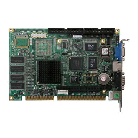
FabiaTech FB2646 Series User instructions

FabiaTech

FabiaTech FB2646 Series User instructions

FabiaTech FB2504 User manual

FabiaTech

FabiaTech FB2504 User manual

FabiaTech Low Power FB2413 User manual

FabiaTech

FabiaTech Low Power FB2413 User manual

FabiaTech Low Power FB2403 User manual

FabiaTech

FabiaTech Low Power FB2403 User manual

FabiaTech FB2412 Series User instructions

FabiaTech

FabiaTech FB2412 Series User instructions

FabiaTech Low Power Series User manual

FabiaTech

FabiaTech Low Power Series User manual

FabiaTech FB2642 User manual

FabiaTech

FabiaTech FB2642 User manual

FabiaTech FB2644 User manual

FabiaTech

FabiaTech FB2644 User manual

FabiaTech Low Power Series User manual

FabiaTech

FabiaTech Low Power Series User manual

FabiaTech FB2730 Series User manual

FabiaTech

FabiaTech FB2730 Series User manual

FabiaTech FX5328 User manual

FabiaTech

FabiaTech FX5328 User manual

FabiaTech FX5407 Series User manual

FabiaTech

FabiaTech FX5407 Series User manual

FabiaTech Fanless Series User manual

FabiaTech

FabiaTech Fanless Series User manual

FabiaTech Fanless FX5613 User manual

FabiaTech

FabiaTech Fanless FX5613 User manual

FabiaTech Fanless Series User manual

FabiaTech

FabiaTech Fanless Series User manual

FabiaTech Fanless FX5321 User manual

FabiaTech

FabiaTech Fanless FX5321 User manual

FabiaTech Low Power FB2503 User manual

FabiaTech

FabiaTech Low Power FB2503 User manual

FabiaTech FB2530 Series User instructions

FabiaTech

FabiaTech FB2530 Series User instructions

FabiaTech Low Power FB2652 User manual

FabiaTech

FabiaTech Low Power FB2652 User manual

FabiaTech FB2505 Series User instructions

FabiaTech

FabiaTech FB2505 Series User instructions

FabiaTech FB2600 User manual

FabiaTech

FabiaTech FB2600 User manual

FabiaTech FB2611 Series User instructions

FabiaTech

FabiaTech FB2611 Series User instructions

FabiaTech FX5206 User manual

FabiaTech

FabiaTech FX5206 User manual

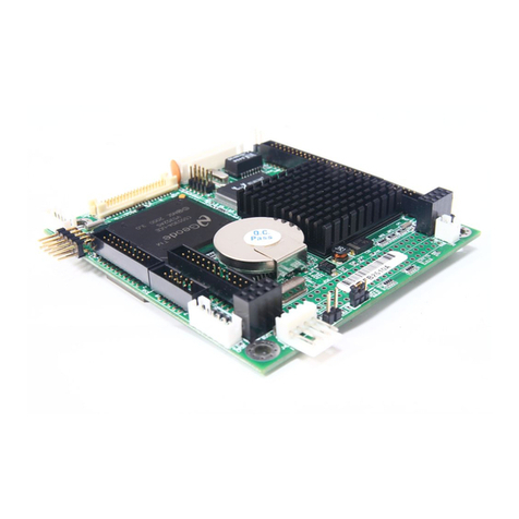
FabiaTech PC104 User manual

FabiaTech

FabiaTech PC104 User manual

Popular Computer Hardware manuals by other brands

AUSTRALIAN MONITOR LIM 1 brochure

AUSTRALIAN MONITOR

AUSTRALIAN MONITOR LIM 1 brochure

Dantel 46062-02 Installation & operation manual

Dantel

Dantel 46062-02 Installation & operation manual

DS Produkte Z 09946 instructions

DS Produkte

DS Produkte Z 09946 instructions

Intel RS25AB080 Tested hardware and operating system list

Intel

Intel RS25AB080 Tested hardware and operating system list

NETGEAR WAG511 - 802.11a/b/g Dual Band Wireless PC... Specifications

NETGEAR

NETGEAR WAG511 - 802.11a/b/g Dual Band Wireless PC... Specifications

SpeedyBee F7 V3 BL32 50A 30x30 Stack user manual

SpeedyBee

SpeedyBee F7 V3 BL32 50A 30x30 Stack user manual

NXP Semiconductors S32K344 user manual

NXP Semiconductors

NXP Semiconductors S32K344 user manual

IEI Technology WAFER-PV-D5252 user manual

IEI Technology

IEI Technology WAFER-PV-D5252 user manual

Aquacal STK0247 Installation & quick start guide

Aquacal

Aquacal STK0247 Installation & quick start guide

StarTech.com PCI1PEX1 instruction manual

StarTech.com

StarTech.com PCI1PEX1 instruction manual

Alphacool GPX-N 1080-M19 instruction manual

Alphacool

Alphacool GPX-N 1080-M19 instruction manual

Mellanox Technologies MTS3610Q-6UNC user manual

Mellanox Technologies

Mellanox Technologies MTS3610Q-6UNC user manual

Shenzhen AARDWOLF PERFORMA 3X user manual

Shenzhen

Shenzhen AARDWOLF PERFORMA 3X user manual

Intel NUC11ATKPE user guide

Intel

Intel NUC11ATKPE user guide

Melexis MLX90601 user manual

Melexis

Melexis MLX90601 user manual

Compaq 5500R - ProLiant - 256 MB RAM Quickspecs

Compaq

Compaq 5500R - ProLiant - 256 MB RAM Quickspecs

Arbor Technology Em104-a5362 user manual

Arbor Technology

Arbor Technology Em104-a5362 user manual

AFL Hyperscale H-Series 7RU Housing installation guide

AFL Hyperscale

AFL Hyperscale H-Series 7RU Housing installation guide

manuals.online logo
manuals.online logoBrands
  • About & Mission
  • Contact us
  • Privacy Policy
  • Terms and Conditions

Copyright 2025 Manuals.Online. All Rights Reserved.