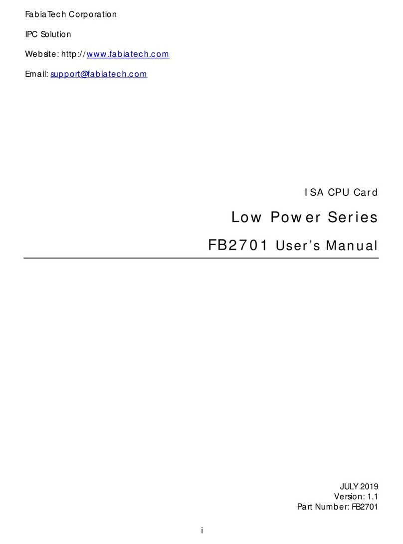
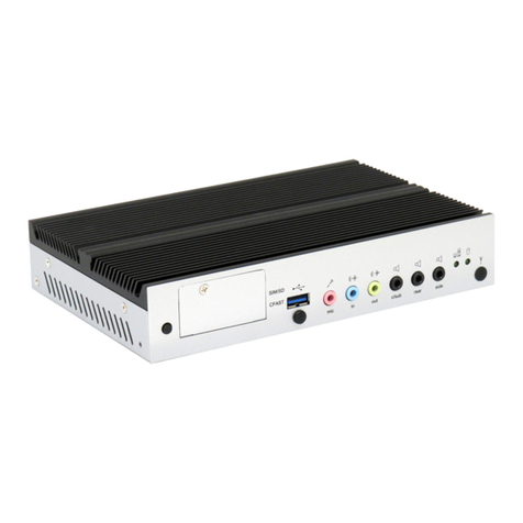
FabiaTech FX5640 Series User manual
Other FabiaTech Computer Hardware manuals
FabiaTech
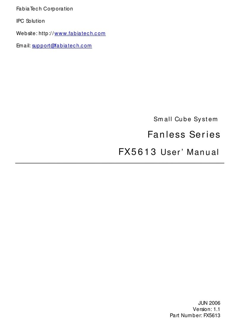
FabiaTech Fanless FX5613 User manual
FabiaTech
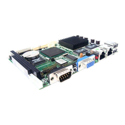
FabiaTech FB2530 Series User instructions
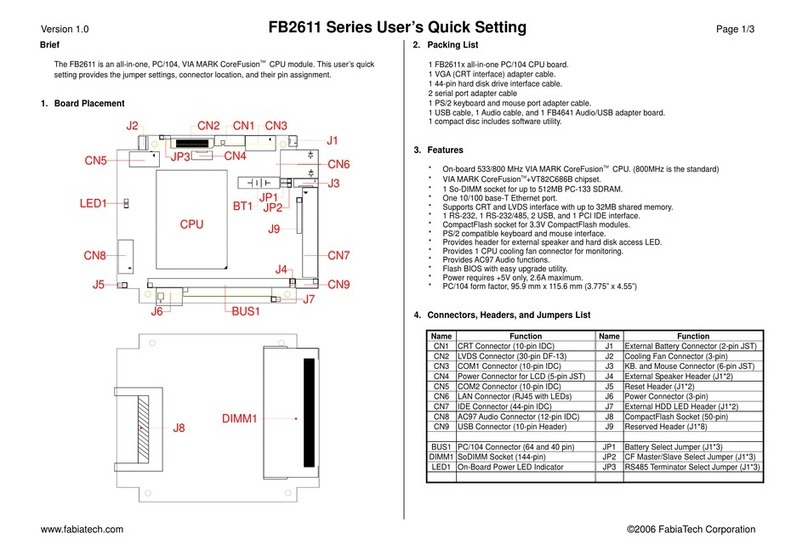
FabiaTech
FabiaTech FB2611 Series User instructions

FabiaTech
FabiaTech Low Power FB2403 User manual
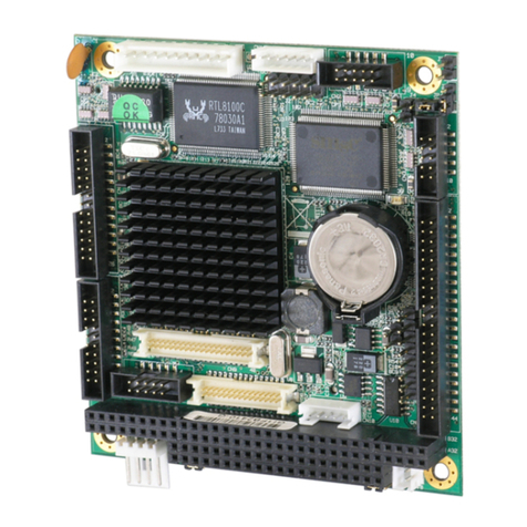
FabiaTech
FabiaTech PC104 User manual

FabiaTech
FabiaTech FB2300 Series User instructions

FabiaTech
FabiaTech Fanless Series User manual

FabiaTech
FabiaTech FB2504 User manual
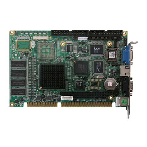
FabiaTech
FabiaTech FB2505 Series User instructions
FabiaTech
FabiaTech Low Power FB2652 User manual
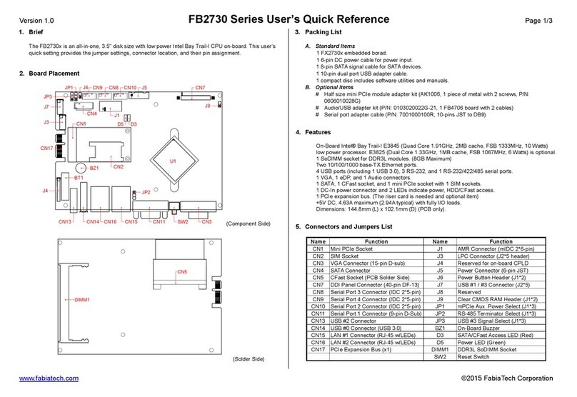
FabiaTech
FabiaTech FB2730 Series User manual
FabiaTech
FabiaTech Low Power FB2413 User manual
FabiaTech
FabiaTech Fanless Series User manual
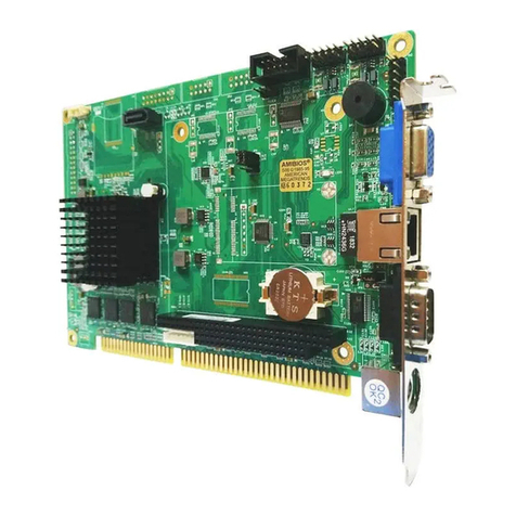
FabiaTech
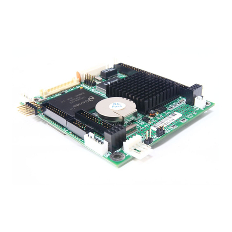
FabiaTech Low Power Series User manual
FabiaTech
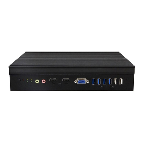
FabiaTech FB2510 Series User instructions
FabiaTech
FabiaTech FX5638 Series User manual
FabiaTech
FabiaTech FB2642 User manual

FabiaTech
FabiaTech Fanless Series User manual
FabiaTech
FabiaTech Low Power FB2503 User manual
FabiaTech
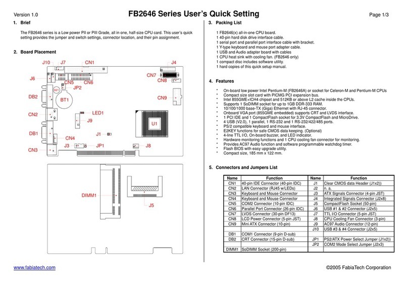
FabiaTech FB2646 Series User instructions
Popular Computer Hardware manuals by other brands

EMC2
EMC2 VNX Series Hardware Information Guide

Panasonic
Panasonic DV0PM20105 Operation manual

Mitsubishi Electric
Mitsubishi Electric Q81BD-J61BT11 user manual

Gigabyte
Gigabyte B660M DS3H AX DDR4 user manual

Raidon
Raidon iT2300 Quick installation guide

National Instruments
National Instruments PXI-8186 user manual
