FAR KJ29 User manual

KJ29
PL
- ISTRUZIONI ORIGINALI
RIVETTATRICE MANUALE PER INSERTI FILETTATI M3 / M10
ISTRUZIONI PER L’USO
- TRANSLATION OF ORIGINAL INSTRUCTIONS
HAND TOOL FOR BLIND RIVET NUTS M3 / M10
OPERATING INSTRUCTIONS
- TRADUCTION DES INSTRUCTIONS ORIGINALES
OUTIL À RIVETER POUR ÉCROUS À SERTIR M3 / M10
MODE D’EMPLOI
- ÜBERSETZUNG VON ORIGINALANLEITUNGEN
HANDWERKZEUG FÜR BLIND-EINNIETMUTTERN M3 / M10
BEDIENUNGSANLEITUNG
- TRADUCCION DE LAS ISTRUCCIONES ORIGINALES
REMACHADORA MANUAL PARA REMACHES ROSCADOS M3 / M10
INSTRUCCIONES DE USO
- TŁUMACZENIE ORYGINALNEJ INSTRUKCJI
NITOWNICA RĘCZNA DO NITONAKRĘTEK GWINTOWANYCH M3 / M10
INSTRUKCJA OBSŁUGI
I
GB
F
D
E

275036062 - KJ 29 – rev 00- ( 03-2013 )
h
12
4356
1 2
0,5 mm
87
9

3
75036062 - KJ 29 – rev 00- ( 03-2013 )
RIVETTATRICE MANUALE PER L'UTILIZZO DI INSERTI FILETTATI CON FILETTATURA DA M3 A M10.
Prima dell'utilizzo accertarsi che la coppia tirante - testina montata sulla rivettatrice sia adeguata alla filettatura dell'inserto che si vuole
serrare,in caso contrario occorre procedere al cambio di formato.
Attenzione: Solitamente la coppia tirante/testina montata sulla rivettarice in confezione corrisponde ad una filettatura di M5.
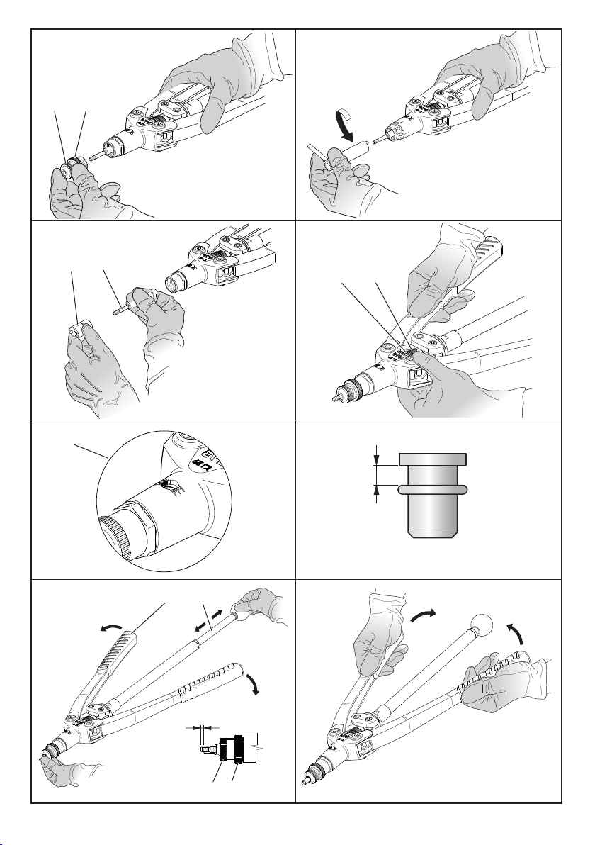
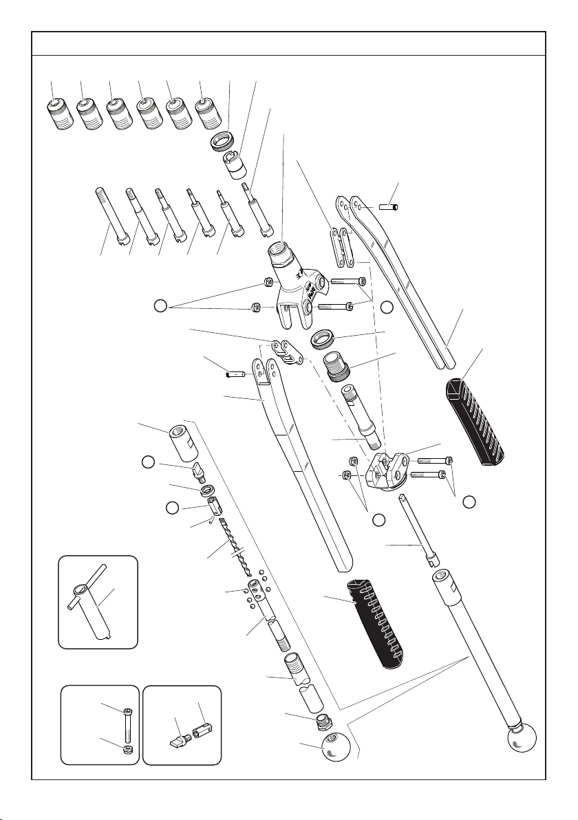
CAMBIO DI FORMATO:
Svitare e togliere la testina ( 1) e la ghiera ( 2). Sbloccare tramite la chiave in dotazione la coppia tirante( 3) ghiera ( 4) ed estrarla dalla
rivettatrice; estrarre il tirante dalla ghiera e sostituirlo scegliendo dal kit di corredo la misura necessaria.Ogni rivettatrice è corredata
di un tirante ed una testina per ogni formato di inserto, le ghiere ( 2 ) e ( 4 ) vengono invece utilizzate con tutti i formati.
REGOLAZIONE DELLA CORSA:
Questa operazione deve essere eseguita prima della messa in opera dell'inserto, in funzione dello spessore del materiale da serrare.
La regolazione si ottiene sbloccando la ghiera ( 5 ) intervenendo poi sul registro ( 6 ) avvitandolo per aumentare la corsa e svitandolo
per diminuirla,avvalendosi dell’indicatore di corsa fig ( 9).Aumentando la corsa si ottiene una maggiore deformazione dell'inserto
con conseguente diminuzione della distanza ( h ). Eseguita la prima regolazione di massima fissare l'inserto sul materiale e rifinire la
regolazione della corsa in base alla stretta che l'inserto opera sul materiale. La corsa ottimale è quella che permette un saldo, ma non
esasperato, serraggio dell'inserto sul materiale: in caso di corsa ridotta si rischia il non perfetto bloccaggio, in caso opposto, cioè
corsa troppo "ampia", si rischia la deformazione del filetto.
REGOLAZIONE DELLA TESTINA:
Una volta definita la corsa regolare la testina ( 1 ) in modo che il tirante faccia presa su tutti i filetti dell'inserto.
Avvitare sul tirante l'inserto filettato in modo che la sua testa vada a battuta con la testina della rivettatrice.
Verificare che il tirante fuoriesca di circa 0,5 mm dall'inserto ,in caso contrario sbloccare la ghiera( 2 ) e registrare la posizione della
testina:avvitandolaaumenteràlasporgenzadeltirante,svitandolalasporgenzadeltirantediminuirà;adoperazioneultimataribloccare
la ghiera ( 2 ). Le operazioni di regolazione descritte devono essere sempre ripetute quando avviene il cambio di formato.
SERRAGGIO DELL'INSERTO:
Portare l'avvitatore ( 7 ) verso l'esterno ed aprire le leve ( 8 ). Avvitare l'inserto sul tirante portando verso l'interno l'avvitatore ( 7 ),
posizionarel'insertonel foropraticatosulmaterialeeserrarlotramitel'azionedelleleve(8).Adoperazioneultimataportarel'avvitatore
verso l'esterno per svitare il tirante dall'inserto ormai serrato.
HAND TOOL FOR BLIND RIVET NUTS FROM M3 TO M10.
Before using it, make sure that the stay bolt and the head assembled on the tool are suitable for the thread of the insert to be used;
otherwise it will be necessary to change the stay bolt and the head size.
Warning: The standard stay bolt and head supplied with the tool is usually M5.
SIZE CHANGE:
Unscrew and take out the head ( 1) and the ring nut ( 2). By the supplied key, unlock the stay bolt ( 3) and the ring nut ( 4); take out
those pieces from the tool, replace the stay bolt choising the correct size from the kit.
Each tool is equipped with a stay bolt and a head for each size; the ring nut ( 2) and ( 4) can be fitted with any insert size.
STROKE ADJUSTMENT:
Adjust stroke before operating the tool, with reference to the thickness of the material to clamp.
Stroke adjustment will be obtained by loosing the ring nut ( 5); screwing the adjusting screw ( 6) the stroke will increase while
unscrewing it, the stroke will be reduced; stroke indicator will help during the adjustment ( 9).
By increasing the stroke, the insert deformation will be wider and therefore, the ( h) distance will be reduced.
By reducing the stroke, the ( h) distance will increase because of the smaller deformation.
When the preliminary adjustment has been made, the insert can be fixed on the material to clamp; complete the stroke adjustment
in accordance with the pressure that the insert exerts on the material. Adjust stroke to obtain steady but not extreme clamp.
In case of reduced stroke, the insert will not be properly locked, otherwise, in case of wider stroke, the thread will be deformed.
HEAD ADJUSTMENT:
After having set the stroke, it is necessary to adjust the head ( 1).
Put the threaded insert on the stay bolt: it is very important that the head of the insert is fully located.
The stay bolt must come out by 0,5 mm from the insert, if this doesn't happen, it is necessary to unlock the ring nut ( 2) and adjust
the head position: by screwing it, the extention of the stay bolt will increase; by unscrewing it, the extention of the stay bolt will be
reduced. After that you can lock again the ring nut ( 2). Every time the insert size is changed this adjustment is always necessary.
INSERT OPERATION:
Move the screwer ( 7) outward and open the levers ( 8), put the insert on the stay bolt moving inward the screwer ( 7). Put the insert
in the hole of the material and pull the insert by the levers ( 8). After that move the levers outward in order to unscrew the stay bolt
from the clamped insert.
I
GB

475036062 - KJ 29 – rev 00- ( 03-2013 )
REMACHADORA MANUAL PARA EL USO DE INSERTOS FILETEADOS CON FILETEADURA DE M3 A M10.
Antes de utilizar asegurarse que la pareja tirante-cabeza montada sobre la remachadora sea adecuada a la fileteadura del inserto que
se desea ajustar, en caso contrario se debe proceder al cambio de formato.
Atencion: Normalmente la pareja tirante-cabeza montada sobre la remachadora de fábrica corresponde a una fileteadura de M5.
CAMBIO DE FORMATO:
Destornillar y quitar la cabeza ( 1 ) y la virola ( 2 ). Desbloquear con la llave en dotación la pareja tirante ( 3 ) virola ( 4 ) y extraerla
de la remachadora; extraer el tirante de la virola y reemplazarlo eligiendo del kit abastecido la medida necesaria. Cada remachadora
es abastecida de un tirante y una cabeza para cada formato de inserto, las virolas ( 2 ) y ( 4 ) son utilizadas con todos los formatos.
REGULACION DE LA CARRERA:
Esta operación debe ser realizada antes de la instalación de la tuerca, en función del espesor del material de ajuste. El ajuste se obtiene
mediante el desbloqueo de la virola ( 5) interviniendo luego en la regulación ( 6) y enroscar para aumentar la carrera, desenroscar
para disminuirla, haciendo uso del indicador de carrera. ( 9).
Aumentando la carrera se obtiene una mayor deformación del inserto con la consiguiente disminución de la distancia ( h). Una vez
realizada la primera regulación de máxima, fijar el inserto en el material y acabar la regulación de la carrera segùn la apretadura que
la tuerca ejerce sobre el material.
La carrera optima es la que permite un firme, pero no exasperado, ajuste de la tuerca sobre el material: en caso de carrera reducida,
se corre el riesgo de tener un imperfecto bloqueo, en caso contrario, con carrera muy " amplia ", se corre el riesgo de la deformación
de la rosca.
REGULACION DE LA CABEZA:
Una vez definida la carrera regular la cabeza ( 1 ) en modo que el tirante haga toma sobre todos los filetes del inserto. Atornillar sobre
el tirante el inserto fileteado en modo que su cabeza vaya a golpe con la cabeza de la remachadora.Verificar que el tirante sobresalga
de aproximadamente 0,5mm. del inserto, en caso contrario desbloquear la virola ( 2) y regular la posición de la cabeza; atornillandola
aumentarálapartesobresalientedeltirante,desenroscandolalapartesobresalientedel tirante disminuirá;conlaoperaciónterminada
bloquear nuevamente la virola ( 2 ). Las operaciones de regulación descriptas deben ser repetidas cada vez que se cambie el formato.
AJUSTE DEL INSERTO:
Llevar el arrancador ( 7 ) hacia el exterior y abrir las palancas ( 8 ). Atornillar el inserto sobre el tirante llevando hacia el interior el
arrancador ( 7 ), posicionar el inserto en la perforación practicada sobre el material y ajustarlo a través de la acción de las
palancas ( 8 ). Con la operación terminada llevar el arrancador hacia el exterior para desenroscar el tirante del inserto ya ajustado.
OUTIL MANUEL POUR L'UTILISATION D'INSERTS DE M3 À M10.
Avant l'emploi vérifier que l'ensemble tirant-tête, monté sur l'outil, soit approprié au filetage de l'insert que l'on veut serrer. Au cas
contraire, il faut pourvoir au changement de diamètre.
Attention: d'habitude l'ensemble tirant-tête assemblé sur l'outil dans le coffret correspond à un filetage de M5.
CHANGEMENT DE DIAMETRE:
Dévisser la tête ( 1) et l'embout ( 2). Desserrer la vis ( 3) et enlever le tirant ( 4); remplacer le tirant en choisissant la dimension
nécessaire dans le kit. Tous les outlis sont livrés avec un tirant et une tête dans chaque diamètre d'insert. L'embout ( 2) et (4 ) est
employé pour tous les formats.
REGLAGE DE LA COURSE:
Cette opération doit être effectuée avant la mise en place de l'insert, en fonction de l'épaisseur du matériel à sertir. Le réglage est
obtenu par le déverrouillage de la bague ( 5) intervenant ensuite sur le dispositif de réglage ( 6) à visser pour augmenter la course et
dévisser pour la diminuer, en se référant à l'indicateur de course (9). En augmentant la course on obtient une plus grande déformation
de l'insert et la diminution conséquente de la distance ( h). Après avoir effectué le réglage préliminaire, fixer l’insert sur le matériel
et affiner le réglage de la course en fonction du serrage de l’insert sur le matériel. La course optimale est celle qui permet le serrage
parfaitement ferme de l’insert sur le matériel, mais pas exagéré: dans le cas d'une course courte, il y a un risque de blocage imparfait,
dans le cas contraire, c'est à dire la course est trop "large", il existe un risque de déformation du filet.
REGLAGE DE LA TETE:
Après le réglage de la course on peut régler la tête (1). Visser l’insert fileté sur le tirant jusqu’au contact de l’insert avec la tête de l’outil.
Vérifier que le tirant sorte de l’insert de 0,5 mm; au cas contraire, débloquer l’embout (2) et régler la position de la tête: en la vissant
pour augmenter, ou en dévissant pour diminuer la sortie du tirant. Après avoir effectué cette opération, bloquer l’embout (2).
Les opérations citées ci-dessus doivent toujours être répétées quand on change de diamètre ou de longueur d’insert.
SERRAGE DE L'INSERT:
Amener le drill ( 7) vers l'extérieur. Visser l'insert sur le tirant en amenant le drill ( 7) vers l'intérieur. Positionner l'insert dans le trou
percé sur le matériel et serrer à l'aide du levier ( 8).A la fin de l'opération, amener le drill vers l'extérieur pour dévisser le tirant de
l'insert déjà serré.
F
E

5
75036062 - KJ 29 – rev 00- ( 03-2013 )
HANDWERKZEUG FÜR BENUTZUNG VON BLINDNIETMUTTERN VON M3 BIS M10.
Vor Gebrauch, nachsehen ob die zwei Teile Zugbolze-Kopf, die auf dem Werkzeug montiert sind, zur Blindnietmutter-Gewinde, die
man klemmen will, passen.
Wenn es nicht den Fall ist, muss man den richtigen Durchmesser auswählen.
Achtung: Normalerweise ist das Paar "Zugbolze-Kopf" auf dem Werkzeug in M5 montiert.
DURCHMESSERWECHSEL:
Kopf(1)und Ansatz(2)abschrauben.DieSchraube(3)lockernunddenZugbolzen(4)wegnehmen;der Zugbolzen wirdgewechselt
in dem man die richtige Dimension aus dem Kit heraus nimmt.
AlleWerkzeugesindmitZugbolzenundKöpfevon jedemDurchmessergeliefert.DenAnsatz( 2)und(4)istfüralleGrössenverdendbar.
HUBEINSTELLUNG:
Die Hubeinstellung muss vor der Einsetzung des Blindnietmutter durchgeführt werden, abhängig von der Dicke des zu klemmenden
Material. Zur Hubeinstellung die Nutmutter ( 5) entsichern und die Nutmutter ( 6) einschrauben, um den Hub zu erhöhen, und sie
abschrauben, um den Hub zu verkleinern. Dazu der Anzeige des Hubes ( 9) sich bedienen.
Wenn man den Hub steigert, ergibt sich eine grössere Verformung der Blindnietmutter und die Distanz ( h).
Nach erster Einstellung muss man ein Blindnietmutter auf dem zu klemmenden Material setzen und den Hub anpassen.
Der beste Hub ist derjenige, der eine feste aber nicht übertriebene Klemmung des Blindnietmutter auf das Material ermöglicht.
Im Falle der Hub reduziert ist, riskiert man eine schlechte Befestigung; im Gegenteil, d.h. der Hub ist zu „weit“, besteht die Gefahr
einer Gewinde-Verzerrung.
KOPF EINSTELLUNG:
Nach der Kursus-Einstellung kann man den Kopf einstellen. Die Blindnietmutter auf den Zugbolzen schrauben bis Kontakt mit
dem Kopf des Werkzeuges. Prüfen dass der Zugbolze von 0,5 mm aus der Blindnietmutter rausschaut; wenn es nicht den Fall
ist, den Ansatz (2) deblockieren. Dann die Kopfstellung einstellen per Schraubung für steigern, oder abschrauben für verringern
um den Zugbolze heraus zu machen. Nach diesem Vorgang, den Ansatz blockieren (2). Dieser Vorgang muss immer wiederholt
werden wenn Grösse oder Länge von Blindnietmutter gewechselt werden.
BLINDNIETMUTTERKLEMMUNG:
Den Drill ( 7) nach aussen bringen. Die Blindnietmutter auf den Zugbolzen schrauben in dem man den Drill ( 7) nach innen bringt.
Dann die Blindniet-Mutter in das gebohrene Loch einlegen und, mit Hilfe vom Hebel ( 8) pressen.
Am Ende diesem Vorganges den Drill gegen aussen bringen um den Zugbolzen von der schon verschraubte Blindnietmutter abzu-
schrauben.
NITOWNICARĘCZNADOUŻYTKUZNITONAKRĘTKAMIGWINTOWANYMIZGWINTEMODM3DOM10.
Przedużyciemnależyupewnićsię,czytrzpienigłowicazamontowanenanitownicysąodpowiedniedogwintunitonakrętki,którąchcesię
zacisnąć,w przeciwnymwypadku,należyprzeprowadzićzmianęformatu.
Uwaga:Zazwyczajtrzpieni głowicazamontowanenanitownicywopakowaniuodpowiadajągwintowiM5.
ZMIANAFORMATU:
Odkręcić i zdjąć głowicę ( 1 ) oraz nasadkę pierścieniową ( 2 ). Odblokować przy użyciu klucza dostarczonego na wyposażeniu trzpien (3 ) i nasadkę pierścieniową ( 4 ) i
wyjąćjez nitownicy;wyjąćtrzpienznasadkiiwymienićje,wybierajączdostarczonegozestawuodpowiednirozmiar. Każdanitownicajestwyposażonaw osobnetrzpien
igłowicędlakażdegoformatunitonakrętki,zaś nasadkipierścieniowe(2)i(4)sąodpowiedniedowszystkichformatów.
USTAWIENIE SKOKU:
Ustaw skok narzędzia przed użyciem odpowiednio do grubości materiału w którym montowana będzie nitonakrętka lub nitośruba.
Ustawienieskokubędziemożliwepopoluzowaniupierścienia(5);dokręcającśrubęregulującą(6)zwiększamyskok,podczasodkręcaniaśrubyregulującejzmniejszymy
skok;skala ustawieniaskokubędziepomocnapodczasustawiania(9). Pozwiększeniuskokuspęczenienitonakrętkibędziewiększeidlategodługość (h).
Po wstępnym ustawieniu można zamontować nitonakrętkę w materiale; skoryguj ustawienie skoku w stosunku do realnego nacisku jaki nitonakrętka wywiera na
materiał podczas spęczania. Ustaw skok tak, by osiągnąć pewne osadzenie nitonakrętki w materiale nie spęczając jej maksymalnie.
Gdy skok będzie zbyt mały nitonakrętka nie zostanie prawidłowo osadzona; w przypadku zbyt dużego skoku gwint ulegnie deformacji.
REGULACJA GŁOWICY:
Pookreśleniuskoku,należywyregulowaćgłowicęnitownicy (1)wtakisposób,abytrzpienchwytałocałygwintnitonakrętki.
Przykręcićna cięgniegwintowanąnitonakrętkę,takabyjejgłówkabyładociśniętadogłowicynitownicy.Upewnićsię,żetrzpienwychodzinaok.0,5mmznitonakrętki;
wprzeciwnymwypadkuodblokowaćnasadkępierścieniową(2)iwyregulowaćpołożeniegłowicy:dokręcającją,trzpienbędziebardziejwystawało;odkręcając,trzpien
schowasię; pozakończeniuoperacjizablokowaćnasadkę(2). Powyższeczynnościregulacyjnemusząbyćpowtarzaneprzykażdejzmianieformatu.
ZACISKANIENITONAKRĘTKI:
Pociągnąćwkrętarkę(7)wkierunkunazewnątrzirozchylićdźwignie(8).Wkręcićnitonakrętkęnatrzpienprzesuwającwkrętarkęwkierunkudowewnątrz(7),umieścić
nitonakrętkęw otworzewykonanymw materialeizacisnąćjąprzyużyciudźwigni(8 ). Pozakończeniuoperacji,przesunąćwkrętarkęwkierunkunazewnątrziwykręcić
trzpienzzałożonejnitonakrętki.
PL
D

675036062 - KJ 29 – rev 00- ( 03-2013 )
N° COD. Qt. DESCRIZIONE DESCRIPTION KIT
171345953 2 Impugnatura Handgrip
271345993 2 Leva Lever
371345949 2 Perno Roll pin
471345948 2 Biella Connecting rod
572B00064 1 Corpo esterno Outside body
6720163 1 Tirante M 5 Tie rod M 5
7710160 1 Ghiera Ring nut
8710159 2 Ghiera Ring nut
9710155 1 Testa M 5 Head M 5
10 710153 1 Testa M 3 Head M 3
11 710154 1 Testa M 4 Head M 4
12 710156 1 Testa M 6 Head M 6
13 710157 1 Testa M 8 Head M 8
14 710158 1 Testa M 10 Head M 10
15 720161 1 Tirante M 3 Tie rod M 3
16 720162 1 Tirante M 4 Tie rod M 4
17 720164 1 Tirante M 6 Tie rod M 6
18 710165 1 Tirante M 8 Tie rod M 8
19 710166 1 Tirante M 10 Tie rod M 10
20A 710623 4 Dado M 6 UNI 7473 Nut M 6 UNI 7473 A
21A 71345903 4 Vite TCCE M6 Screw TCCE M6 A
22 71345895 1 Ghiera di registro Regulation ring nut
23 72A00218 1 Raccordo Connector
24 71345654 1 Cannotto Sleeve
25 712285 1 Innesto Clutch
26 71345764 1 Cannotto avvitatore Screwer sleeve
27B 710639 1 Innesto Clutch B
28 710647 1 Cuscinetto 618/9 Bearing 618/9
29 710649 1 Spina elastica ø 3 x 10 UNI 6874 Spring pin ø 3 x 10 UNI 6874
30B 710640 1 Dado Nut B
31 710704 1 Vite a tortiglione Elicodal shaft
32 710646 6 Sfera 7/32" Ball 7/32"
33 710642 1 Cannotto corsoio avvitatore Screwer sliding sleeve
34 710643 1 Corpo esterno avvitatore Outside body
35 710644 1 Ghiera Ring nut
36 710648 1 Pomello Knob
37 712290 1 Chiave Wrench
KITA
74000069 Kit Vite M 6 Screw M 6 kit
20A 710623 2 Dado M 6 UNI 7473 Nut M 6 UNI 7473
21A 71345903 2 Vite TCCE M6 Screw TCCE M6
KITB
740639 Kit Innesto Clutch kit
27B 710639 1 Innesto Clutch
30B 710640 1 Dado Nut
KIT Indica che il particolare viene venduto in Kit
composti da particolari diversi in quantità
diverse.
It indicates that the part is sold in kits consisting of different
parts in different quantities.
KIT
PARTI DI RICAMBIO • SPARE PARTS • PIECES DETACHEES • ERSATZTEILE • PIEZAS DE REPUESTO •
CZĘŚCI ZAMIENNE

7
75036062 - KJ 29 – rev 00- ( 03-2013 )
PARTI DI RICAMBIO • SPARE PARTS • PIECES DETACHEES • ERSATZTEILE • PIEZAS DE REPUESTO •
CZĘŚCI ZAMIENNE
KIT B
KIT A
37
7
8
9
10
11
12
13
14
5
4
6
19 18 17 16 15
3
2
1
3
20 A
4
2
26
27 B
28
29
31
30 B
32
33
34
35
36
25
20 A
23
21 A
1
24
8
22
21 A
20A(x2)
21A(x2) 30B(x1)
27B(x1)

875036062 - KJ 29 – rev 00- ( 03-2013 )
N° COD. Qt. DESCRIPTION BESCHREIBUNG KIT
171345953 2 Poignée Handgriff
271345993 2 Levier Hebel
371345949 2 Pivot Stift
471345948 2 Bielle Umlenkhebel
572B00064 1 Corps extérieur Aussenschaft
6720163 1 Tirant M 5 Gewindedorn M 5
7710160 1 Bague Nutmutter
8710159 2 Bague Nutmutter
9710155 1 Tête M 5 Kopfteil M 5
10 710153 1 Tête M 3 Kopfteil M 3
11 710154 1 Tête M 4 Kopfteil M 4
12 710156 1 Tête M 6 Kopfteil M 6
13 710157 1 Tête M 8 Kopfteil M 8
14 710158 1 Tête M 10 Kopfteil M 10
15 720161 1 Tirant M 3 Gewindedorn M 3
16 720162 1 Tirant M 4 Gewindedorn M 4
17 720164 1 Tirant M 6 Gewindedorn M 6
18 710165 1 Tirant M 8 Gewindedorn M 8
19 710166 1 Tirant M 10 Gewindedorn M 10
20A 710623 4 Ecrou M 6 UNI 7473 Mutter M 6 UNI 7473 A
21A 71345903 4 Vis TCCE M6
Schraube TCCE M6
A
22 71345895 1 Bague de registre Spannmutter
23 72A00218 1 Raccord Anschlussstück
24 71345654 1 Tube Röhrchen
25 712285 1 Embrayage Kupplung
26 71345764 1 Tube visseur Schraubrohr
27B 710639 1 Embrayage Kupplung B
28 710647 1 Coussinnet 618/9 Lager 618/9
29 710649 1 Goupille élastique ø 3 x 10 UNI 6874 Spannstift ø 3 x 10 UNI 6874
30B 710640 1 Ecrou Mutter B
31 710704 1 Arbre elicoidale Schraubenfoermige Welle
32 710646 6 Bille 7/32" Kugel 7/32"
33 710642 1 Tube coulissant visseur Gleitschraubrohr
34 710643 1 Corps extérieur Aussenschaft
35 710644 1 Bague Nutmutter
36 710648 1 Bouton Knopf
37 712290 1 Clé Schlüssel
KITA
74000069 Kit vis M 6 Kit Schraube M 6
20A 710623 2 Ecrou M 6 UNI 7473 Mutter M 6 UNI 7473
21A 71345903 2 Vis TCCE M6 Schraube TCCE M6
KITB
740639 Kit embrayage Kit kupplung
27B 710639 1 Embrayage Kupplung
30B 710640 1 Ecrou Mutter
KIT Indique que la pièce est vendue dans des
KITS composés de diverses pièces dans des
quantités différentes.
Dieses Wort gibt an, daß der Teil in KIT von verschiedenen
Teilen in unterschiedlichen Mengen verkauft wird.
KIT
PARTI DI RICAMBIO • SPARE PARTS • PIECES DETACHEES • ERSATZTEILE • PIEZAS DE REPUESTO •
CZĘŚCI ZAMIENNE

9
75036062 - KJ 29 – rev 00- ( 03-2013 )
PARTI DI RICAMBIO • SPARE PARTS • PIECES DETACHEES • ERSATZTEILE • PIEZAS DE REPUESTO •
CZĘŚCI ZAMIENNE
KIT B
KIT A
37
7
8
9
10
11
12
13
14
5
4
6
19 18 17 16 15
3
2
1
3
20 A
4
2
26
27 B
28
29
31
30 B
32
33
34
35
36
25
20 A
23
21 A
1
24
8
22
21 A
20A(x2)
21A(x2) 30B(x1)
27B(x1)

10 75036062 - KJ 29 – rev 00- ( 03-2013 )
N° COD. Qt. DESCRIPCIÓN
OPIS
KIT
1 71345953 2 Empuňadura Rekojesci
2 71345993 2 Palanca Dzwignia
3 71345949 2 Perno Sworzeń
4 71345948 2 Biela Łącznik
5 72B00064 1 Cuerpo externo Korpus zewnetrzny
6 720163 1 Ensamblaje tirante M 5 Korek M 5
7 710160 1 Virola Nasadka pierscieniowa
8 710159 2 Virola Nasadka pierscieniowa
9 710155 1 Cabeza M 5 Główka M 5
10 710153 1 Cabeza M 3 Główka M 3
11 710154 1 Cabeza M 4 Główka M 4
12 710156 1 Cabeza M 6 Główka M 6
13 710157 1 Cabeza M 8 Główka M 8
14 710158 1 Cabeza M 10 Główka M 10
15 720161 1 Ensamblaje tirante M 3 Korek M 3
16 720162 1 Ensamblaje tirante M 4 Korek M 4
17 720164 1 Ensamblaje tirante M 6 Korek M 6
18 710165 1 Tirante M 8 Korek M 8
19 710166 1 Tirante M 10 Korek M 10
20A 710623 4 Tuerca M 6 UNI 7473 Nakrętka M 6 UNI 7473 A
21A 71345903 4
Tornillo TCCE M6
Śruba TCCE M6 A
22 71345895 1 Virola de regulación Nasadka regulacyjna
23 72A00218 1 Empalme contenedor Złączka
24 71345654 1 Manguito Tulejka
25 712285 1 Embrague Złącze
26 71345764 1 Manguito atornillador Tulejka wkrętarki
27B 710639 1 Embrague Złącze B
28 710647 1 Cojinete 618/9 Łożysko 618/9
29 710649 1 Clavija elastico ø 3 x 10 UNI 6874 Kolek sprezysty ø 3 x 10 UNI 6874
30B 710640 1 Tuerca Nakrętka B
31 710704 1 Tornillo helicoidal Śruba ślimakowa
32 710646 6 Bola 7/32" Kula 7/32"
33 710642 1 Manguito corredizo atornillador Tulejka przesuwna wkrętarki
34 710643 1 Cuerpo externo atornillador Korpus zewnętrzny wkrętarki
35 710644 1 Virola Nasadka pierscieniowa
36 710648 1 Perilla Pokrętło
37 712290 1 Llave Klucz
KITA
74000069 Kit tornillo M 6 Zestaw śruby M 6
20A 710623 2 Tuerca M 6 UNI 7473 Nakrętka M 6 UNI 7473
21A 71345903 2 Tornillo TCCE M6 Śruba TCCE M6
KITB
740639 Kit embrague Zestaw złącza
27B 710639 1 Embrague Złącze
30B 710640 1 Tuerca Nakrętka
KIT Indica que la pieza se vende en juegos
formados por piezas distintas en cantidades
distintas.
Oznacza, że dany detal jest sprzedawany w Zestawach złożonych z
różnych detali w różnych ilościach.
KIT
PARTI DI RICAMBIO • SPARE PARTS • PIECES DETACHEES • ERSATZTEILE • PIEZAS DE REPUESTO •
CZĘŚCI ZAMIENNE

11
75036062 - KJ 29 – rev 00- ( 03-2013 )
PARTI DI RICAMBIO • SPARE PARTS • PIECES DETACHEES • ERSATZTEILE • PIEZAS DE REPUESTO •
CZĘŚCI ZAMIENNE
KIT B
KIT A
37
7
8
9
10
11
12
13
14
5
4
6
19 18 17 16 15
3
2
1
3
20 A
4
2
26
27 B
28
29
31
30 B
32
33
34
35
36
25
20 A
23
21 A
1
24
8
22
21 A
20A(x2)
21A(x2) 30B(x1)
27B(x1)

SISTEMI DI FISSAGGIO
FASTENING SYSTEMS • SYSTEMES DE FIXATION
VERBINDUNGSSYSTEME • SISTEMAS DE FIJACION
SYSTEMY MOCOWANIA •
www.far.bo.it
L’elenco dei centri di assistenza è disponibile sul Ns. sito
web: http://www.far.bo.it ( Organizzazione )
The list of the service centres is available on our website
http://www.far.bo.it ( Organization )
La liste des centres d’assistance est disponible sur notre
site internet http://www.far.bo.it ( Organisation )
Die Liste der Reparaturservices ist verfügbar unter unserer
Webseite http://www.far.bo.it ( Organisation )
La lista de los servicios postventa es disponible en nuestro
sitio web http://www.far.bo.it ( Organización )
Listapunktówserwisowychjestdostępnananaszejstronieinternetowej
http://www.far.bo.it ( Organizacja )
Список сервисных центров приведен на нашем веб-сайте
http://www.far.bo.it ( )
I
F
E
PL
RUS
GB
D
SEDE • HEAD OFFICE • SIEGE
HAUPTSITZ • SEDE
SIEDZIBA • ОФИСНЫЙ ЦЕНТР :
S.r.l. Uninominale
40057 Quarto Inferiore - Bologna - Italy
Via Giovanni XXIII, 2
Tel. +39 - 051 6009511
Ufficio Vendite Fax +39 - 051 767443
E-mail: commerciale@far.bo.it
Export Dpt. Fax +39 - 051 768284
E-mail: export@far.bo.it
DEPOSITO • WAREHOUSE • DEPOT
WARENLAGER • ALMACEN
ODDZIAŁ • СКЛАД :
20099 Sesto San Giovanni
Milano
Italy
Via Archimede, 8
Tel. +39 - 02 2409634
Fax +39 - 02 26222279
E-mail: milano@far.bo.it
Table of contents
Other FAR Power Tools manuals