manuals.online logo
Brands
  1. Home
  2. •
  3. Brands
  4. •
  5. Festo
  6. •
  7. Terminal Block
  8. •
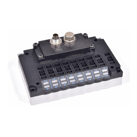
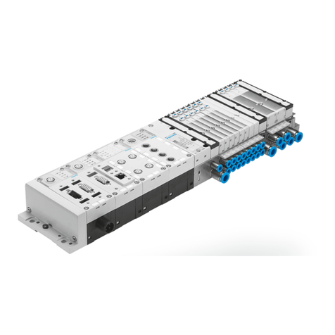
  9. Festo MPA-S Series User manual

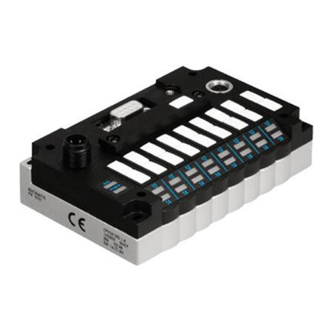
Festo MPA-S Series User manual

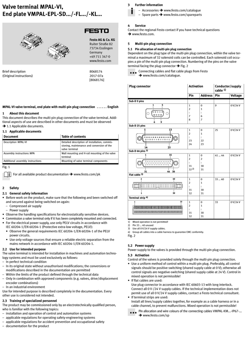
Brief description
MPA-S/MPA-F
with multipin
connector type:
MPA...-MPM-VI
– English
8080182
2017-12d
[8080184]
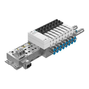
Valve terminal MPA-S/MPA-F
Festo MPA...-MPM-VI 2017-12d2
Translation of the original instructions
Documentation on the product
For all available product documentation
èwww.festo.com/pk
Copyright:
Festo SE & Co. KG
Ruiter Straße 82
73734 Esslingen
Germany
Internet: http://www.festo.com
E-Mail: service_international@festo.com
Reproduction, distribution or sale of this document or communication of
its contents to others without express authorization is prohibited.
Offenders will be liable for damages. All rights reserved in the event that
a patent, utility model or design patent is registered.
English 3............................................
Festo MPA...-MPM-VI 2017-12d English 3
1 User instructionsEnglish
The MPA-S/MPA-F valve terminal has been designed ex
clusively for controlling pneumatic actuators. The maxi
mum values specified in the section “Technical specifica
tions” must be observed here. Detailed information can be
found in the Pneumatics Manual P.BE-MPA-... or
P.BE-MPAF-...
Warning
SSwitch off the power supply before connecting or
disconnecting plugs (otherwise this could lead to
functional damage).
SUse only power units which guarantee reliable
electrical isolation of the operating voltage as per
IEC/DIN EN 60204-1 Observe also the general
requirements for PELV power circuits as per
IEC/DINEN60204-1.
Please note
Commission only a valve terminal which has been fitted
and wired completely.
Festo MPA...-MPM-VI 2017-12d English4
2 Multipin connection
2.1 Multipin socket
Caution
The components of the valve terminal contain electros
tatically sensitive elements. The components will be
damaged if you touch the contact surfaces of the plug
connectors and if you do not observe the regulations
for handling electrostatically sensitive components.
Long signal cables reduce the immunity to interference.
Do not exceed the maximum permitted signal cable
length of 10 m.
Recommendation:
Use the following 25-pin multipin socket with cable from
the Festo range of acessories for connecting the MPA valve
terminal with multipin connection:
Multipin socket with cable
VMPA-KMS1-8-...
VMPA-KMS2-8-...
VMPA-KMS1-24-...
VMPA-KMS2-24-...
Maximum 8 valve solenoid coils
can be actuated.
Maximum 24 valve solenoid coils
can be actuated.
Festo MPA...-MPM-VI 2017-12d English 5
14
25
13 1
Pin 1 corresponds to address 0
Pin 24 corresponds to address 23
2.2 Pin assignment of the sub-D multipin plug
Notes on the following table:
– Core colour applies to cable type: VMPA-KMS...
– Colour code of the core colours as per DIN/IEC 757
– Addr. = address
Plug Pin Addr. Core colour Pin Addr. Core colour
114
25
13 1
2
3
4
5
6
7
8
9
10
11
12
13
0
1
2
3
4
5
6
7
8
9
10
11
12
WH
GN
YE
GY
PK
BU
RD
VT
GY PK
RD BU
WH GN
BN GN
WH YE
14
15
16
17
18
19
20
21
22
23
24
25
13
14
15
16
17
18
19
20
21
22
23
0 V 1)
YE BN
WH GY
GY BN
WH PK
PK BN
WH BU
BN BU
WH RD
BN RD
WH BK
BN
BK
1) 0 V for positive-switching control signals; 24 V for negative-
switching control signals; mixed operation is not permitted.
Festo MPA...-MPM-VI 2017-12d English6
3 Controlling the valve terminal
Use a uniform method of control. Preferably, all control
signals should be positive-switching (1-switching), other
wise all control signals negative-switching (0-switching).
Mixed mode control is not permitted.
3.1 Address assignment of the valves
– Assign the addresses in ascending order without gaps
(see example).
– Addess assignment does not depend on whether
blanking plates or valve plates are fitted.
– Depending on the electronic module, a valve location
occupies the following number of addresses:
Number of
addresses
Electronic module
MPA 1 MPA 2
one address VMPA1-MPM-EMM-4VMPA2-MPM-EMM-2
two addresses VMPA1-MPM-EMM-8VMPA2-MPM-EMM-4
– If an electronic module occupies 2 addresses, the
following applies:
– pilot solenoid 14 occupies the lower-value address;
– pilot solenoid 12 occupies the higher-value address.
Festo MPA...-MPM-VI 2017-12d English 7
Example of address assignment
Caution
Note that addresses may be shifted if the valve terminal
is extended at a later stage.
In the example an MPA valve terminal with the folllowing
components is addressed:
Components MPA 1 MPA 2
Sub-bases 2 (8 valve locations) 2 (4 valve locations)
Electronic module 1 VMPA1-MPM-EMM-8
1 VMPA1-MPM-EMM-4
1 VMPA2-MPM-EMM-4
1 VMPA2-MPM-EMM-2
For controlling the valves, each valve solenoid coil (referred
to in the following as coil) is assigned to a certain pin of the
multipin plug.
Festo MPA...-MPM-VI 2017-12d English8
Pin Address Valve location
number
Coil Electronic module
1
2
0
1
0 14
12
VMPA1-MPM-EMM-8
3
4
2
3
1 14
12
5
6
4
5
2 14
12
7
8
6
7
3 14
12
9 8 4 14 VMPA2-MPM-EMM-2
10 9 5 14
11 10 6 14 VMPA1-MPM-EMM-4
12 11 7 14
13 12 8 14
14 13 9 14
15
16
14
15
10 14
12
VMPA2-MPM-EMM-4
17
18
16
17
11 14
12
... ... ... ... ...
25 0 V 1)
1) 0 V for positive-switching control signals; 24 V for control signals;
mixed operation is not permitted.
Festo MPA...-MPM-VI 2017-12d English 9
Example of address assignment (seen from above):
2
15 14 17
1234
7
4
98
35
6
15
2
1
0
13
4
5
6
789
10 11 12 13
16
1
aJ
1Addresses of coils 14
(manual override 14)
2Addresses of coils 12
(manual override 12)
3LED for coil 12
4LED for coil 14
5Unused valve location
6Pin assignment with
electronic module
VMPA2-MPM-EMM-4
occupies two addresses
per valve location
7Supply block for additional
pressure supply
8Pin assignment with electronic
module VMPA1-MPM-EMM-4
occupies one address per valve
location
9Pin assignment with electronic
module VMPA2-MPM-EMM-2
occupies one address per valve
location
aJ Pin assignment with electronic
module VMPA1-MPM-EMM-8
occupies two addresses per
valve location
Festo MPA...-MPM-VI 2017-12d English10
4 Technical specifications and accessories
Type: MPA...-MPM-VI 1) MPA1 MPA2
Number of valve locations 4, 8, 12...24 2) 2, 4, 6...24 2)
Current consumption per solenid
coil at 24 V
– Rated pick-up current/duration
– Rated current with current
reduction
80 mA/25 ms
25 mA
100 mA/50 ms
20 mA
Control voltage:
– Rated value (protected against
incorrect polarity)
– Tolerance
24 V DC
± 25 % (18...30 V DC)
Protection class as per DIN 40050 IP65 (fitted completely)
Protection against electric shock By the use of PELV current
circuits (protection against direct
and indirect contact as per
IEC/DIN EN60204-1)
Ambient temperature
Storage temperature
- 5 ... + 50 °C
- 20 ... + 40 °C
Electromagnetic compatibility
– Interference emitted 3)
– Immunity to interference 4)
See declaration of conformity
èwww.festo.com
1) Dimensions and materials: See Pneumatics Manual
2) Maximum 24 valve solenoid coils can be controlled
3) The valve terminal is intended for industrial usage
4) The maximum permitted signal cable length is 10 m

Other manuals for MPA-S Series

1

This manual suits for next models

5

Other Festo Terminal Block manuals

Festo CPV GE-ASI-4E4A-Z-CE Series User manual

Festo

Festo CPV GE-ASI-4E4A-Z-CE Series User manual

Festo VABM-B10-30E Series User manual

Festo

Festo VABM-B10-30E Series User manual

Festo CPV..-DI01 series Parts list manual

Festo

Festo CPV..-DI01 series Parts list manual

Festo CPX-FB38 Parts list manual

Festo

Festo CPX-FB38 Parts list manual

Festo CPV -GE-DN2-8 Parts list manual

Festo

Festo CPV -GE-DN2-8 Parts list manual

Festo VABM-B10-25E Series User manual

Festo

Festo VABM-B10-25E Series User manual

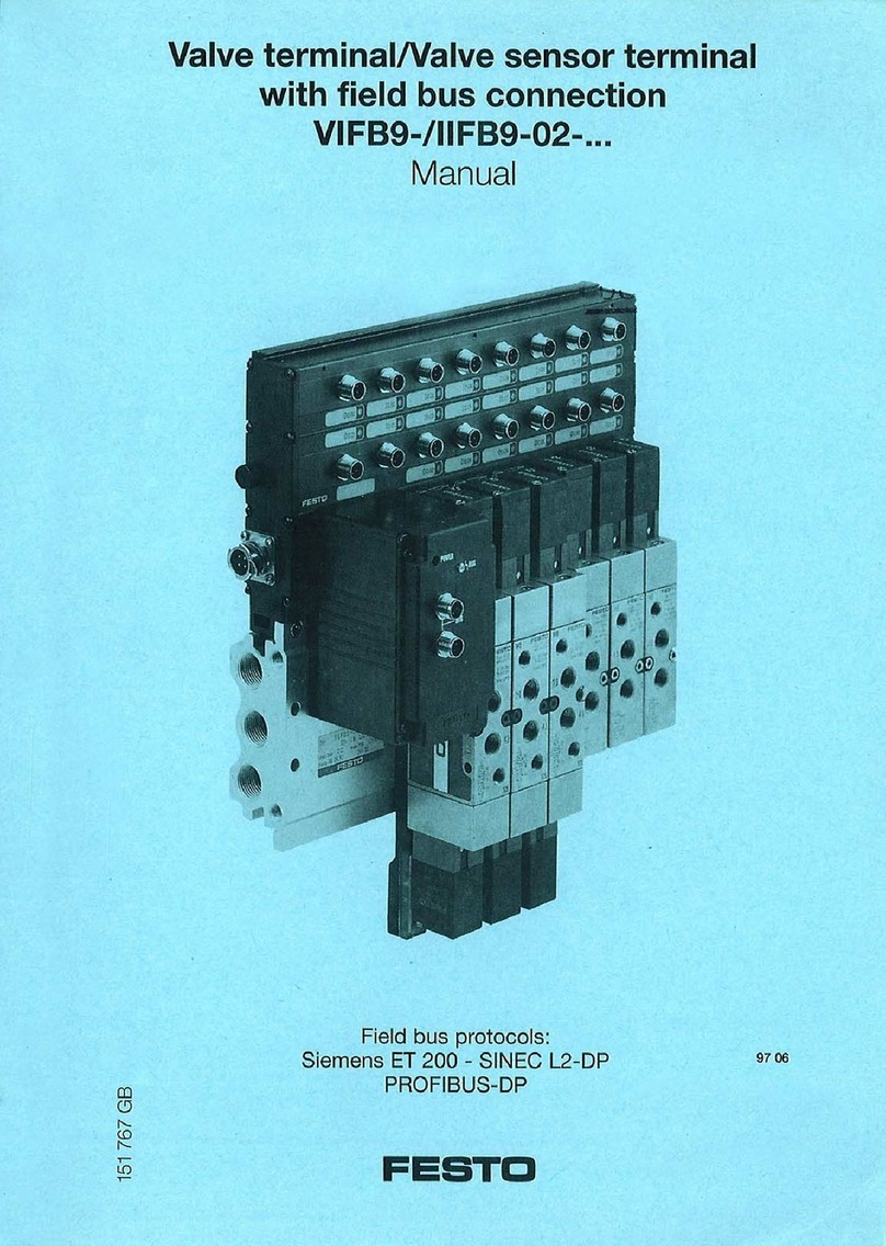
Festo VIFB9-02 Series User manual

Festo

Festo VIFB9-02 Series User manual

Festo CPV GE-CO2-8 Series User manual

Festo

Festo CPV GE-CO2-8 Series User manual

Festo CPV -GE-ASI-8E8A-Z Series User manual

Festo

Festo CPV -GE-ASI-8E8A-Z Series User manual

Festo Compact Performance CPV Series User manual
Festo

Festo Compact Performance CPV Series User manual

Festo MPAL-VI User manual

Festo

Festo MPAL-VI User manual

Festo VTSA Series User manual

Festo

Festo VTSA Series User manual

Festo CPV -GE-ASI-8E8A-Z Series Parts list manual

Festo

Festo CPV -GE-ASI-8E8A-Z Series Parts list manual

Festo CPX-FB33 Operating and installation instructions

Festo

Festo CPX-FB33 Operating and installation instructions

Festo CPVSC1-EPR Series User manual

Festo

Festo CPVSC1-EPR Series User manual

Festo VABM-B10 E Series User manual

Festo

Festo VABM-B10 E Series User manual

Festo MPA-S Series Parts list manual

Festo

Festo MPA-S Series Parts list manual

Festo CPV GEASI-4 Series Parts list manual

Festo

Festo CPV GEASI-4 Series Parts list manual

Festo CPV-SC-DP Parts list manual

Festo

Festo CPV-SC-DP Parts list manual

Festo CPV GE-CO2-8 Series User manual

Festo

Festo CPV GE-CO2-8 Series User manual

Festo CPA VI Series User manual

Festo

Festo CPA VI Series User manual

Festo CPE PRS Series User manual

Festo

Festo CPE PRS Series User manual

Festo CPV10-VI-P Series User manual

Festo

Festo CPV10-VI-P Series User manual

Festo CPV GE-IB-8 Series User manual

Festo

Festo CPV GE-IB-8 Series User manual
Popular Terminal Block manuals by other brands
Crestron CLT-PWS75 installation guide

Crestron

Crestron CLT-PWS75 installation guide

Omron SRT2-PD16T manual

Omron

Omron SRT2-PD16T manual

Panasonic TY-FB30DHD3D operating instructions

Panasonic

Panasonic TY-FB30DHD3D operating instructions

Schmalz Compact Terminal SCTSi operating instructions

Schmalz

Schmalz Compact Terminal SCTSi operating instructions

manuals.online logo
manuals.online logoBrands
  • About & Mission
  • Contact us
  • Privacy Policy
  • Terms and Conditions

Copyright 2025 Manuals.Online. All Rights Reserved.