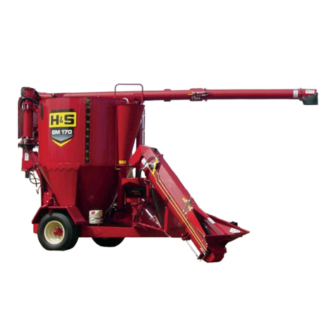
H&S GM 170 Installation and maintenance instructions

Manufactured By
H&S MANUFACTURING CO.,INC.
P.O. BOX 768 (715) 387-3414 FAX (715) 384-5463
MARSHFIELD, WISCONSIN 54449
OPERAOPERA
OPERAOPERA
OPERATT
TT
TOR’S MANUOR’S MANU
OR’S MANUOR’S MANU
OR’S MANUALAL
ALAL
AL
ANDAND
ANDAND
AND
PP
PP
PARAR
ARAR
ARTS LISTTS LIST
TS LISTTS LIST
TS LIST
WARNING READ AND UNDERSTAND THIS MANUAL
BEFORE OPERATING THIS EQUIPMENT
UNSAFE OPERATION OR MAINTENANCE OF THIS EQUIPMENT CAN RESULT IN
SERIOUS INJURY OR DEATH
HSMFG0106
GM 170

H&S GM 170
OPERATOR’S & PARTS MANUAL
CONTENTS
Warranty & Warranty Registration Card. . . . . . . . . . . . . . . . . . . . . . . . . . . . . . . . . . . . . . . . . . . . .. . 1-2
Dealer Pre-Delivery & Delivery Checklist. . . . . . . . . . . . . . . . . . . . . . . . . . . . . . . . . . . . . . . . . . . .. . 3-4
BeAlert Symbol... . . ... . . ... . . ... . . ... . . ... . . ... . . ... . . ... . . ... . . ... . . .. . . ... . . ... . . .5
ExplanationofSafety Signs... ... . .. . ... ... ... ... . .. . .. . ... ... ... ... . .. . ... ..... ... ..... 6
Danger-WarningSigns.. . ... ... . ... . .. . ... . ... . .. . ... . ... ... . ... . ... ... . .... ... . ..7-10
Warning-OwnerMustRead andUnderstand.. ... .. ... .. ... ..... ... .. ... .. ... ..... ... .. .13
BoltTorque Chart. . . . . . . . . . . . . . . . . . . . . . . . . . . . . . . . . . . . . . . . . . . . . . . . . . . . . . . . . . . . . . . . . . 14
Preparing for Operation. . . . . . . . . . . . . . . . . . . . . . . . . . . . . . . . . . . . . . . . . . . . . . . . . . . .. . . . . . . . . .15
Set-Up &Assembly. . . . . . . . . . . . . . . . . . . . . . . . . . . . . . . . . . . . . . . . . . . . . . . . . . . . . . ..... . . ... . 16
Storage. . . . . . . . . . . . . . . . . . . . . . . . . . . . . . . . . . . . . . . . . . . . . . . . . . . . . . . . . . . . . . . . . . . . . . . . . . .16
Transporting.. ..... .. ..... .. ..... .. ..... .. ..... .. ..... .. ..... .. ..... .. .. ... .. .. ... .. ..17
Operation. . . . . . . . . . . . . . . . . . . . . . . . . . . . . . . . . . . . . . . . . . . . . . . . . . . . . . . . . . .. . . . . . . . . . . .18-26
Adjustments. . . . . . . . . . . . . . . . . . . . . . . . . . . . . . . . . . . . . . . . . . . . . . . . . . . . . . . . . .. . . . . . . . . . 27-29
LubricationGuide.. ... ... ... ... ... ... ... ... ... ... . .. . .. . .. . .. . .. . .. . .. . .. ... ... ... 30-32
Service. . . . . . . . . . . . . . . . . . . . . . . . . . . . . . . . . . . . . . . . . . . . . . . . . . . . . . . . . . . .. . . . . . . . . . . . .33-38
OptionalFeatures&Accessories... ... ... ... ... ... ... . .. . .. . .. . .. . .. . .. . .. . ... ... .. .39-40
TroubleshootingGuide. ... ... ... ... ... ... ... ... .. . .. . .. . .. ... ... ... ... ... ..... ... ..41-45
Decal Location & Identification. . . . . . . . . . . . . . . . . . . . . . . . . . . . . . . . . . . . . . . . . . . . . . . .. . . .46-49
Instructionsfor OrderingParts-About Improvements.... ... ... ... . .. . .. . .. . .. . .. . ... ... ..50
ServiceandParts Notes.. ... ... .. ... ... .. . .. ... ... .. ... ... .. ... ... .. ... ... .. ... .. . .. ..51
Parts. . . . . . . . . . . . . . . . . . . . . . . . . . . . . . . . . . . . . . . . . . . . . . . . . . . . . . . . . . . . . . . . . . . . . . . . . .52-82
Specifications. . . . . . . . . . . . . . . . . . . . . . . . . . . . . . . . . . . . . . . . . . . . . . . . . . . . . . . .Inside Back Cover

WARRANTY
FILL OUT AND MAIL
IMMEDIATELY TO MAKE
WARRANTY EFFECTIVE
WARRANTY REGISTRATION
Date of Purchase
Purchaser Address
City State Zip
Product Model# Serial#
Dealer Address
City State Zip
Signature of Original Buyer
2/04
H & S WARRANTY
H & S Manufacturing Co., Inc. (“H & S”) warrants this product to be free from defect in material and workmanship. Except as
noted below, this warranty term is twelve (12) months from the date of delivery of the product to the original purchaser by an
authorized H & S dealer. Under this warranty , H & S will repair or replace, at its option, any covered part which is found to be
defective in material or workmanship during the applicable warranty term. In no case will the covered repair cost of a part or parts
exceed the replacement cost of that part. Warranty service must be performed by H & S or a dealer authorized by H & S to sell
and/or service the product involved, which will use only new or remanufactured parts or components furnished by H & S. This
warranty includes approved parts and labor to fix the product but does not include, and the purchaser is responsible for, any service
call and/or transportation of the product to and from the dealer’s place of business, for any premium charged for overtime labor
requested by the purchaser, and for any service work not directly related to any defect covered under this warranty. This warranty
includes only those components of the product manufactured by H & S. Warranty for any component not manufactured by H & S
including, but not limited to, engines, batteries, tires, rims, hydraulic motors, pumps, etc. are covered by the warranty, if any, provided
separately by their respective manufacturers.
This warranty in all its parts, is extended solely to the original purchaser of the product, is terminated upon any subsequent
transfer or sale from or by the original purchaser and extends no third party benefits or rights whatsoever.
The warranty term for any product used in any commercial, custom, for hire or rental application, is limited to six (6) months
from the date of delivery of the product to the original purchaser by an authorized H & S dealer.
Polybonded (polyethylene and plywood) panels utilized in H & S Manure Spreaders are warrantied, to the original purchaser,
to not wear through and the polyethylene overlay to not tear free of the plywood for the functional life of the spreader. This specific
warranty on polybonded panels includes only replacement of any defective panel part without any allowance for labor beyond the
terms of the general warranty (12 or 6 months), and is further limited to manure spreaders used to spread normal agicultural manure.
This warranty does not include: (1) Any product that has been altered or modified in ways not approved by H & S; (2) Depreciation
or damage caused by normal wear, misuse, improper or insufficient maintenance, improper operation, accident or failure to follow
the product Operator’s Manual recommendations and product decal recommendations; (3) Normal maintenance parts and service;
(4) Repairs made with parts other than those available from H & S or performed by anyone other than H & S or a dealer authorized
by H & S to sell and/or service the product involved.
To secure warranty service the purchaser must report the product defect to a dealer authorized by H & S to sell and/or service
the product involved within the applicable warranty term together with evidence of the warranty start date and make the product
available to that dealer within a reasonable period of time.
THERE ARE NO WARRANTIES WHICH EXTEND BEYOND THE DESCRIPTION ON THE FACE OF THIS WARRANTY. H & S
and the companies affiliated with it makes no warranties, representations, or promises, express or implied, as to the performance or
freedom from defect of its products other than those set forth above and NO IMPLIED WARRANTY OF MERCHANTABILITY,
FITNESS OR FITNESS FOR A PARTICULAR PURPOSE IS MADE. IN NO EVENT WILL THE DEALER, H&S OR ANY COMPANY
AFFILIATED WITH H&S BE LIABLE FOR INCIDENTAL OR CONSEQUENTIAL DAMAGES. The ONLY REMEDY the purchaser has
in connection with the breach of performance of any warranty on H & S products are those set forth above.
The selling dealer has no authority to make any representation or promise on behalf of H & S, or to modify the terms or limitations
of this warranty in any way.
-1-


BUSINESS REPLY MAIL
FIRST CLASS MAIL Permit No.195 Marshfield, WI 54449
POSTAGE WILL BE PAID BY ADDRESSEE
H&S Manufacturing Co., Inc.
PO Box 768
Marshfield, WI 54449-9963
NO POSTAGE
NECESSARY
IF MAILED
IN THE
UNITED STATES
IMPORTANT!
Tear on dotted line, provide the information requested on
the card. The H&S Warranty is valid “only” after this card
is received and recorded at H&S Mfg. Co. Mail at
once. No postage is required in the U.S.A.
-2-

H&S DEALER PRE-DELIVERYCHECK LIST
AFTER COMPLETION, DEALER SHOULD REMOVE AND RETAIN FOR RECORDS
After the 170 Grinder-Mixer has been completely set-up, check to be certain it is in correct operating order
before delivering to the customer. The following is a list of points to inspect. Check off each item as you
have made the proper adjustments and found the item operating satisfactorily.
Grinder-Mixer was not damaged in shipment. Check for dents and loose or missing parts.
Report damage immediately to H&S Manufacturing Co., Inc.
All bolts and fasteners are tight.
Mixer has been correctly assembled according to instructions in this manual. Wheel nuts and
all other fasteners are tightly secured.
All grease fittings have been lubricated.The transmission and cyclonic reservoir are filled to
proper levels. See Lubrication Chapter of this manual for details.
Hydraulic pump, motors, hoses and fittings are properly attached.
Guards and shields are secure.
Screens fit properly into the mill and the mill cover closes and latches tightly.
Wheels are properly mounted.
Tires are inflated to 80 PSI (563 kpa).
Belts are properly adjusted.
Rear Drive Chain tension is properly adjusted. See Adjustment Chapter of this manual.
Discharge auger door operates smoothly.
Decals are in place and legible.
Lights and wiring functioning properly if applicable.
Connect the Mixer onto a proper horsepower 540 RPM or 1000 RPM (if applicable) tractor and
attach the PTO. Connect the scale and lights if applicable. Run the Grinder-Mixer and make
sure all components operate properly.
PTO guard turns freely.
Hydraulic system does not leak under pressure.
Electronic Scale (if provided) operates properly.
Implement and all components are functioning properly.
-3-
(Remove Dealer File Copy At Perforation)

-4-

AFTER COMPLETION, DEALER SHOULD REMOVE AND RETAIN FOR RECORDS
Serial Number
(Dealer’s Name)
(Signature of Pre-Delivery Inspector) (Inspection Date)
DEALER DELIVERYCHECK LIST
This check list that follows is an important reminder of valuable information that should be passed on to the
customer at the time this machine is delivered.
Check off each item as you explain it to the customer.
This delivery check list, when properly filled out and signed assures the customer that the Pre-delivery
service was satisfactorily performed.
Explain to the customer that the pre-delivery inspection was made.
Explain to the customer all the safety precautions they must excercise when operating this
unit.
Explain to customer that regular lubrication is required for proper operation and long life of
machine. Show customer the Lubrication Chapter of the Operator’s Manual.
Explain to customer that drain plugs must be installed before operating of grinder-mixer.
Give the customer Operator’s Manual and make sure they read and understand all
operating and service instructions.
Record model and serial number on this page and page 50 of this Manual.
Have customer sign a completed “Warranty Registration,” and mail it promptly.
DateDelivered Dealer’s Name
By
Signature of Original Buyer
Note: Warranty is not valid until warranty card is completed and returned to H & S Mfg. Co., Inc.
(Remove Dealer File Copy At Perforation)
SWINGING INTAKEAUGER (SIA)(if applicable)
Guards, shields, and attaching hardware are in place and properly secured.
SIA lifting, locking and supporting mechanisms function correctly. Counter-balance spring and
brake are properly adjusted. SeeAdjustments Chapter of this manual.
Transport lock mechanism engages and disengages correctly. Safety locking clip is attached to
the transport bracket.
Hydraulic motor and speed control levers operate properly during operation.
-5-
H&S DEALER PRE-DELIVERYCHECK LIST(CONT.)
Decals are in place and legible.
Model Number

-6-

BE
ALERT! YOUR SAFETY
IS INVOLVED.
THIS SYMBOL IS USED THROUGHOUT THIS BOOK WHENEVER YOUR PERSONAL SAFETY IS
INVOLVED. TAKE TIME TO BE CAREFUL. REMEMBER: THE CAREFUL OPERATOR IS THE BEST
OPERATOR. MOST ACCIDENTS ARE CAUSED BY HUMAN ERROR. CERTAIN PRECAUTIONS
MUST BE OBSERVED TO PREVENT THE POSSIBILITY OF INJURY OR DAMAGE.
TRACTORS
This operator’s manual uses the term “Tractor” when identifying the power source.
-7-
H & S MANUFACTURING CO. INC.
SAFETY INFORMATION

RECOGNIZE SAFETY INFORMATION
This is the safety-alert symbol. When you see this symbol
on your machine or in this manual, be alert to the potential
for personal injury.
Follow recommended precautions and safe operating
practices.
UNDERSTAND SIGNAL WORDS
A signal word- DANGER, WARNING, or CAUTION - is
used with the safety-alert symbol. DANGER identifies the
most serious hazards.
Safety signs with signal word DANGER or WARNING are
typically near specific hazards.
General precautions are listed on CAUTION safety signs.
FOLLOW SAFETY INSTRUCTIONS
Carefully read all safety messages in this manual,
and all safety signs on your machine. Follow all
recommended precautions and safe operating
procedures.
Keep signs in good condition. Immediately replace
any missing or damaged signs.
-8-
SAFETY INFORMATION

-9-
SAFETY INFORMATION

SAFETY INFORMATION
-10-

SAFETY INFORMATION
-11-

SAFETY INFORMATION
-12-

TRACTORS:
This operators manual uses the term “Tractor” when identifying the the power source.
WARNING
TO PREVENT SERIOUS INJURY OR DEATH
Study The Above Safety Rules
ATTENTION - BE ALERT - YOUR SAFETY IS INVOLVED
BEFORE YOU ATTEMPT TO OPERATE THIS EQUIPMENT, READ AND STUDY THE FOLLOWING
INFORMATION. IN ADDITION, MAKE SURE THAT EVERY INDIVIDUAL WHO OPERATES OR WORKS
WITH THIS EQUIPMENT, WHETHER FAMILY MEMBER OR EMPLOYEE, IS FAMILIAR WITH THESE
SAFETYPRECAUTIONS.
H&S Mfg. Co. always takes the operator and their safety into consideration and guards exposed moving
parts for their protection. However, some areas cannot be guarded or shielded in order to assure proper
operation. In addition, the operators manual and decals on the machine itself warn you of further
dangerand should beread andobserved closely.
-13-
KNOW HOW TO STOPMACHINE BEFORE STARTING IT.
If the machine becomes clogged or for servicing, Stop the tractor engine, remove ignition key
and allow all mechanisms to stop. Before cleaning or working on the machine, detach the PTO
shaft, and completely disengage the tractor hydraulics.
DO NOT attempt to perform maintenance or repair with tractor running, PTO and hydraulic hoses
connected to the tractor.
DO NOT step up on machine at any time while in operation.
DO NOT allow minors to operate or be near the machine.
DO NOTALLOW PERSONNEL OTHER THAN THE QUALIFIED OPERATOR NEAR THE
MACHINE.
STAY CLEAR of discharge auger when in operation.
Keep hands, feet, and clothing away from all moving parts when the Grinder-Mixer is in operation.
Loose or floppy clothing should not be worn by the operator.
Be sure the machine is clear of people, tools, and other objects before engaging PTO.
Do not step over PTO shaft: Stay clear of PTO at all times.
NEVER start the Grinder-Mixer until all guards and safety shields are secured in place.
Never operate Grinder-Mixer with a PTO speed greater than the recommended PTO RPM.
STAY CLEAR of hydraulic lines, they may be under extreme pressure or heat.
NEVER open or plug the water drain holes with the Mixer running.

-14-

TRACTION CONNECTIONS
PTO
Hook the Grinder-Mixer to the tractor drawbar, and attach the Grinder-Mixer PTO to the tractor PTO shaft
locking it into position.
1. Maintain a straight alignment between the grinder-mixer and the tractor.
2. Maintain a 15-1/2” distance between the lock on the tractor PTO and hole on grinder-mixer hitch
for a 540 RPM machine.
3. Maintain a 17” distance between the lock on the tractor PTO and hole on grinder-mixer hitch for a
1000 RPM machine.
4. Maintain a distance of 6”- 12” between the top of the tractor drawbar and the center of the tractor
PTO. An 8” distance is standard.
PREPARING FOR OPERATION
PREPARING MIXER
* Properly lubricate the grinder-mixer, checking the transmission and cyclonic reservoir oil levels, and
filling if necessary before operating the grinder-mixer.
*All drain plugs must be properly installed and secured.
* Follow the procedures outlined in the Operation Chapter of this manual for installing the mill screen.
* The tank lid and the discharge auger door must be closed and the cyclone cover must be open.
* Start the tractor, engage the PTO at idle speed and increase the rpm’s until the grinder-mixer is running
at the rated PTO speed. Begin the grinding process.
-15-
Hydraulics
TheGM170 requires a4 hosehook-up; 2hoses forthe dischargeauger lift,and 2hoses forthe discharge
auger rotation.

WHEELS & TIRES
The Grinder-Mixer is shipped without the rims and tires installed on the axle hubs. Install the rims and
tires, and torque the wheel nuts to 90 ft-lb (124 N-m). Inflate the 12.5L x 15 - 20 ply tires to 80 PSI (563
kpa).
DRAIN PLUGS & DRAIN COVER
When the Grinder-Mixer is delivered, the drain plug on the back plate of the transfer auger will be in the
storage position. See the diagram below for the storage position. When the GM 170 is ready for delivery,
installthedrain plug intheback plate ofthetransfer auger. If themixer is equippedwith aSwinging Intake
Auger (SIA), the drain plug will also be in the storage position. Upon delivery, also install the drain plug in
the drain hole in the bottom of the SIA attachment.
IMPORTANT: Never open or plug the water drain holes with the mixer running.
SET-UP & ASSEMBLY
-16-
STORAGE
IMPORTANT: If the GM 170 is stored outside, the water drain holes must be left unplugged. Before the
mixer is going to be operated, re-install the plugs. Before operating the mixer after a rain, check the
several vulnerable areas for water accumulation. As necessary, drain the water before using the mixer.
NOTE: After water has been drained from the mixer, it is advisable to run the GM 170 while empty for a
period of time in an attempt to dry the mixer before grinding to eliminate any sticking of material and
possible plugging.
TransferAuger Drain Plug In Storage Position. SIADrain Plug In Storage Position.

SMV BRACKET & REFLECTORS
Thegrinder-mixer isequippedwith a SMVbracket. Red reflectorstripsare located onthe rear ofthe tank
andon the SIA(if applicable).
TRANSPORTING
-17-
TRANSPORT LIGHTING
Anoptional highwaytransportlighting kit isavailable.

-18-
OPERATION
EMERGENCY SHUTDOWN
In an emergency or in case a foreign object enters the mill
inlet, stop mixer operation immediately by disengaging the
tractor PTO.
GENERAL INFORMATION
Check entire unit carefully before first operation. Tighten bolts and set screws that might have come
loose in shipping. Lubricate as explained in the Lubrication Chapter in this manual.
NOTE:These procedures must be done before grinding;
1.) Grinder mill door is closed.
2.) The collector cover is open,
2.)The tank lid is closed,
3.) The unloading auger shut-off door is closed.
Operate the mixer on level ground for uniformity of mix. Maintain a straight-line alignment between the
tractor and mixer to prolong the life of the drive line components.
Maintain the tractor rated PTO speed which produces a mill cylinder speed of 2700 RPM, to obtain the
most efficient grind. Do not exceed a cylinder speed of 3000 RPM. Before grinding, the unloading auger
shut-off door must be closed.
Add supplements after a small amount of feed has been ground, then dry granular materials.
NOTE:Do not grind feed with high moisture content. This may cause plugging.Abnormally damp crops
will not feed or mix well.
Grinding should be stopped when the feed in the windows begins to drop.
IMPORTANT: Overfilling the mixing tank will place unnecessary stress on the drive line components.
Keep the tank lid closed and properly latched so that if the tank is accidentally overfilled, the lid can pop
open and release the feed inside the tank.
The two full-length windows on the tank are calibrated with numbers representing bushels of ground
feed.
NOTE:Optional modelsofelectronicscalesareavailablefor accurate weight measurements and rations.
Stop the tractor and disengage the mill/blower drive sheave pin after grinding. Start the tractor and allow
the mixer to continue running for several minutes to thoroughly mix the ground feed.Allow the mixer to
continue running during transport, disengaging the PTO on corners or turns.
IMPORTANT: Whentransporting themixer andmixing, disengagethe tractorPTObeforeturning corners
to prevent damage to the PTO driveline.
Other manuals for GM 170
1
Table of contents
Other H&S Farm Equipment manuals

H&S
H&S HDNR 7+4 User manual

H&S
H&S LW1100 User manual

H&S
H&S 1236 User manual

H&S
H&S Top Shot 5215 User manual

H&S
H&S FORAGE BOX User manual

H&S
H&S H D 7+4 FEEDER BOX Installation and maintenance instructions

H&S
H&S 2957 User manual

H&S
H&S HI-DUMP 9215 User manual

H&S
H&S 2958 Programming manual

H&S
H&S GM 170 Installation and maintenance instructions
Popular Farm Equipment manuals by other brands

Kellfri
Kellfri 27-MD500 operating instructions

Iluminar
Iluminar CMH 1000W DE user manual

AGENTA
AGENTA WE VITRO MicroRocker instruction manual

Powerfix Profi
Powerfix Profi KH 3221 operating instructions

Gravely
Gravely 79106700 instruction sheet

Pottinger
Pottinger NOVACAT V 10000 Original operating instructions