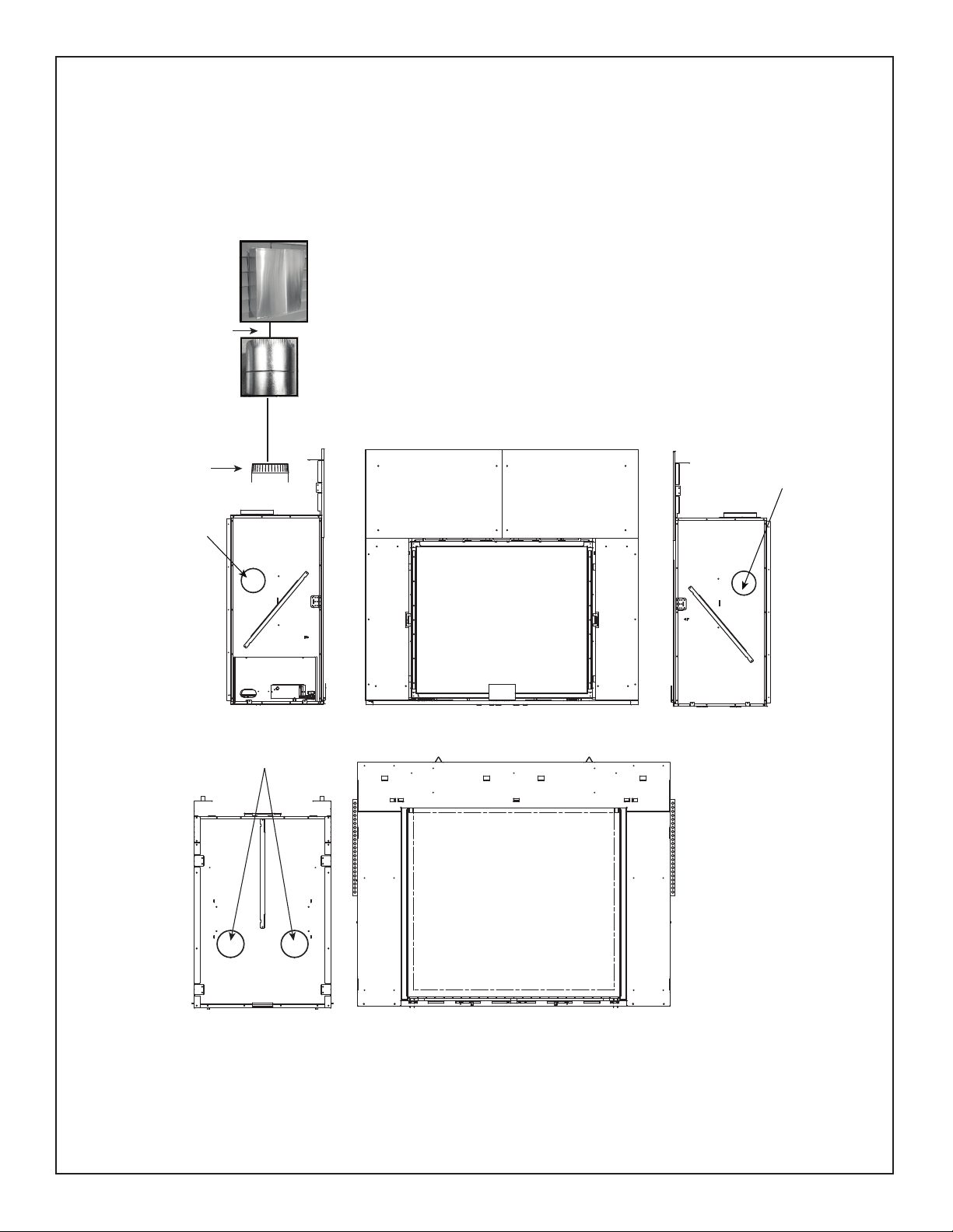
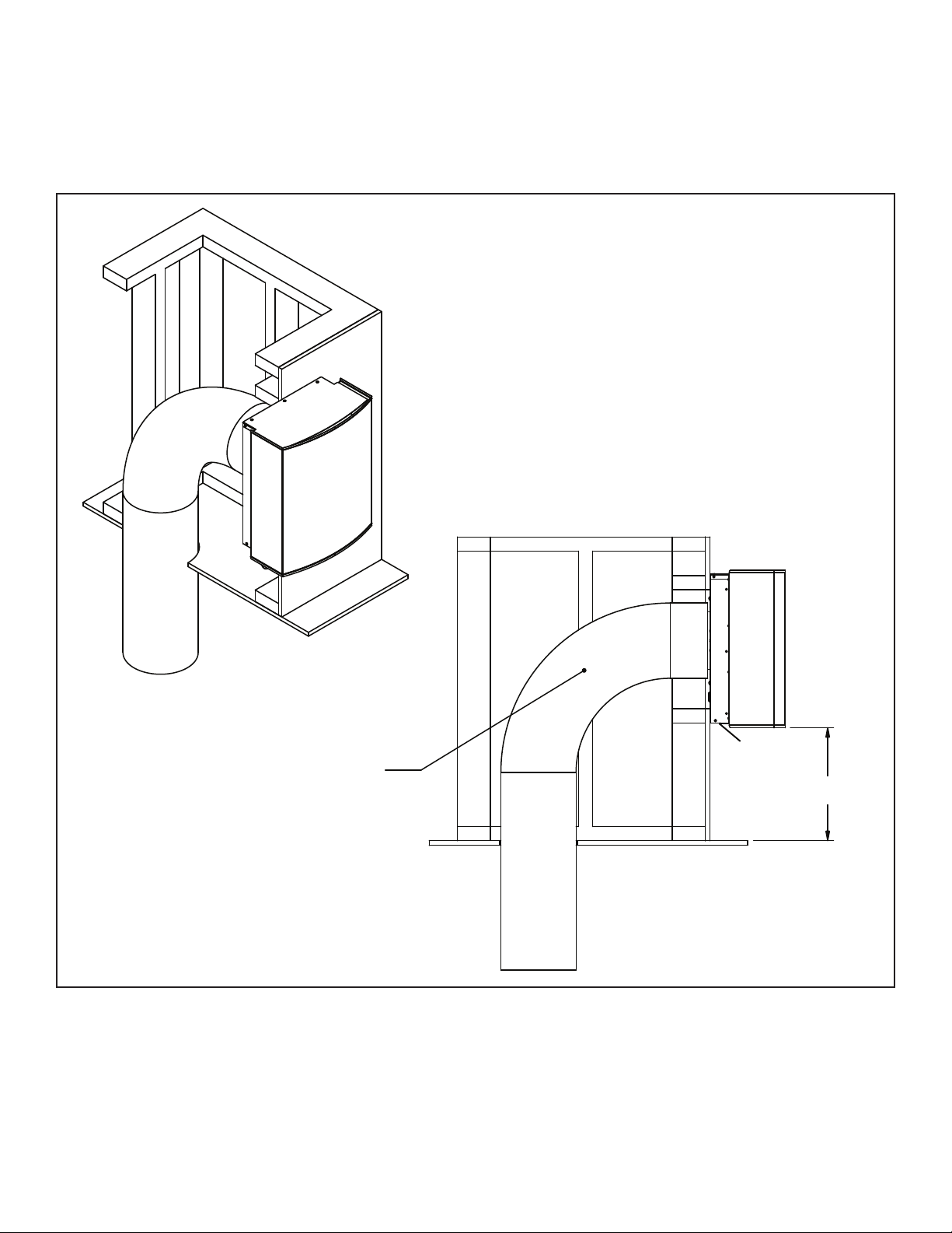
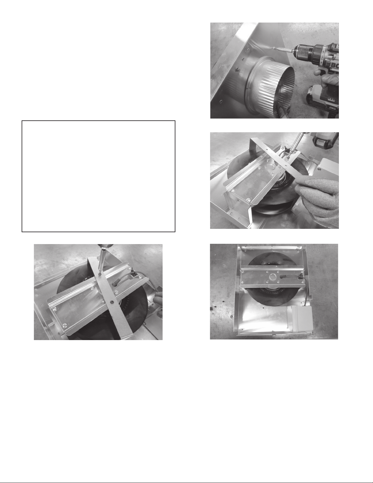
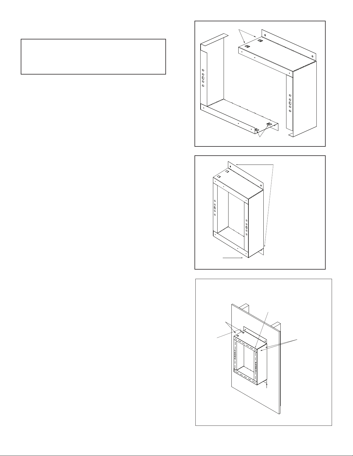
Hearth & Home 6000C-IFT User manual
Other Hearth & Home Fireplace Accessories manuals

Hearth & Home
Hearth & Home Contour60 User manual

Hearth & Home
Hearth & Home FRAME-V12 User manual

Hearth & Home
Hearth & Home LOGS-550BE-B User manual

Hearth & Home
Hearth & Home Grand Vista 36 User manual

Hearth & Home
Hearth & Home BRICK-6K-TG User manual

Hearth & Home
Hearth & Home BRICK-MI30 User manual

Hearth & Home
Hearth & Home HEAT-OUT-GAS User manual

Hearth & Home
Hearth & Home Outdoor Lifestyles LPTK-ODPLAZA-L User manual

Hearth & Home
Hearth & Home ODGF42 User manual

Hearth & Home
Hearth & Home Firebrick Termination Cap DVP-FBHT User manual

Hearth & Home
Hearth & Home MANOR36 User manual

Hearth & Home
Hearth & Home SRV2384-070 User manual

Hearth & Home
Hearth & Home BK-GAS User manual

Hearth & Home
Hearth & Home MI25-5040CS-BK User manual

Hearth & Home
Hearth & Home FBG-4832-EDGE User manual

Hearth & Home
Hearth & Home SMART WALL B Installation instructions

Hearth & Home
Hearth & Home AVFLST48SSODK User manual

Hearth & Home
Hearth & Home PIER-DV36IN User manual

Hearth & Home
Hearth & Home Outdoor Lifestyles ODCOUG-36NR User manual

Hearth & Home
Hearth & Home 550-TRIM3-BK-B Manual


Popular Fireplace Accessories manuals by other brands


Town & Country Fireplaces
Town & Country Fireplaces 22150051 instructions

Travis Industries
Travis Industries 33 DVI installation instructions

Lopi
Lopi Hearthview 864 user manual

Lennox Hearth Products
Lennox Hearth Products LENNOX MPE-33R installation instructions

Dimplex
Dimplex DFP6776C install guide

Napoleon
Napoleon W175-0689 instruction manual

Travis Industries
Travis Industries 95400424 installation instructions

Osburn
Osburn ZERO CLEARANCE KIT installation instructions

Majestic
Majestic QUARTZPLA36IN installation instructions

Napoleon
Napoleon DBPO36 installation instructions

Dimplex
Dimplex SMP-130-E install guide

Empire Comfort Systems
Empire Comfort Systems LS50TINF installation instructions