manuals.online logo
Brands
  1. Home
  2. •
  3. Brands
  4. •
  5. Hearth & Home
  6. •
  7. Fireplace Accessories
  8. •
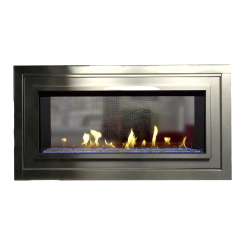
  9. Hearth & Home FRAME-V12 User manual

Hearth & Home FRAME-V12 User manual

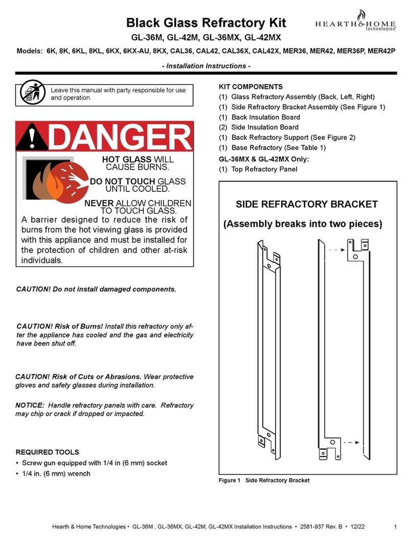
1Hearth & Home Technologies • AMB-LIGHTS Installation Instructions • 2273-934 Rev. B • 9/14
AMB-LIGHTS
Models: FRAME-V12, FRAME-S21, FRAME-H31
STUDIO-V12, STUDIO-S21, STUDIO-H31, DF-FSV7, DF-FSS7, DF-FSH7
Installation Instructions
Leave this instruction with party responsible for
use and operation.
CAUTION! Do not install damaged components. If
you received components that are damaged, contact
your dealer for assistance.
WARNING
This appliance has been supplied with an integral barrier
to prevent direct contact with the fixed glass panel. Do
NOT operate the appliance with the barrier removed.
Contact your dealer or Hearth & Home Technologies if the
barrier is not present or help is needed to properly install one.
HOT SURFACES!
Glass and other surfaces are hot during
operation AND cool down.
Hot glass will cause burns.
• Do not touch glass until it is cooled
• NEVER allow children to touch glass
• Keep children away
• CAREFULLY SUPERVISE children in same room as
fireplace.
• Alert children and adults to hazards of high temperatures.
High temperatures may ignite clothing or other
flammable materials.
• Keep clothing, furniture, draperies and other flammable
materials away.
CAUTION! Risk of Cuts or Abrasions. Wear protective
gloves and safety glasses during installation. Sheet metal
edges are sharp.
KIT CONTENTS:
• LED 12 Volt Power Supply
• Wire Clip, 1/4 in. diameter (10)
• Wire Tie, 6 in. (10)
• LED Switch Box
• 1 X 1 Velcro Assembly (3)
• Nut, Keps #10-32 (4)
• LED Strips/Wire Assembly
• Extension Wire (Optional)
• LED Brackets (2)
INSTALLATION
1. All steps to install the AMB-LIGHTS Kit will be done on the
lower back side of the decorative front. Figure 1 shows
the features used to determine the top and bottom of the
decorative front.
2. Place the LED switch box on the lower stud of the deco-
rative front. See Figure 2. For top mounting of the LED
switch bracket, see page 3.
Note: Exact position of LED switch box may vary depend-
ing on appliance model.
3. Place LED brackets onto top and bottom studs. The bot-
tom of the LED bracket will share the stud with the LED
switch box and the 12V power supply ground. See Figure
2, Figure 3 and Figure 8. Bend LED brackets to achieve
the desired angle for light distribution. A 45 degree angle
may achieve the optimum lighting effect. The brackets
will be secured with keps nuts in Step 9.
Note: The AMB-LIGHTS kit is not approved for use with
the Radius door.
Figure 2. View from Back Side of Decorative Front
(H31 Decorative Front Shown)
LOWER
LOWER
STUD
STUD
LED
LED
SWITCH
SWITCH
BOX
BOX
LED BRACKET
LED BRACKET
STANDOFF LOCATED AT TOP OF DOOR
2 CLIPS LOCATED AT BOTTOM OF DOOR
THIS END UP
Figure 1. Decorative Front - Rear View
Note: Tab is oriented
toward outside of
toward outside of
decorative front.
decorative front.
2 Hearth & Home Technologies • AMB-LIGHTS Installation Instructions • 2273-934 Rev. B • 9/14
6 IN. MINIMUM
6 IN. MINIMUM
6. Connect the yellow and black 12V power supply wires to
the red and black wires from the LED switch box. See
Figure 4 and Figure 7.
7. Connect the LED switch box to the LED strips/wire as-
sembly. See Figure 4 and Figure 7.
8. Position the 12 volt power supply box at least six inches
from the outer edge of the door to allow for clearance
for the outer wrap. Secure with velcro piece(s). The
12 volt power supply should rest on the bottom return
bend of the door. See Figure 5.
9. Secure the ground wire from the 12V power supply.
The ground terminal should come into contact with
the unpainted portion of the LED switch box. See Fig-
ure 8. Secure top and bottom studs with keps nuts.
Figure 3. LED Strips Installed with Zip Ties
LED STRIP
LED STRIP
POSITIONED
POSITIONED
ON LED
ON LED
BRACKET
BRACKET
ZIP TIES
ZIP TIES
CONNECT WIRES HERE
CONNECT WIRES HERE
Figure 4.
STEP 7
STEP 7
STEP 6
STEP 6
Figure 5.
WIRE CLIPS
WIRE CLIPS
WIRE CLIPS
WIRE CLIPS
TOP STUD
TOP STUD
12V POWER
12V POWER
SUPPLY
SUPPLY
4. Remove the adhesive backing from the LED strips and
adhere the LED strips in place on the LED brackets. See
Figure 3.
5. Secure each LED Strip with five zip ties. Place zip ties in
the “white” areas of the LED strips. Do not allow zip ties
to cover the light emitters on the LED strips. Trim ends of
zip ties. See Figure 3. Note: Only four of the five zip ties
are visible.
LOWER
LOWER
STUD
STUD
10. Wrap excess wire neatly using the provided plastic clips.
Keep it away from the mesh area and secure it tight to
the door. See Figure 3 and Figure 5.
3Hearth & Home Technologies • AMB-LIGHTS Installation Instructions • 2273-934 Rev. B • 9/14
Figure 6. LED Color Combinations
COLOR TOP
SWITCH
MIDDLE
SWITCH
BOTTOM
SWITCH
OFF IN IN IN
GREEN OUT IN IN
RED IN OUT IN
DARK BLUE IN IN OUT
WHITE OUT OUT OUT
YELLOW OUT OUT IN
PURPLE IN OUT OUT
LIGHT
BLUE OUT IN OUT
LED Switch Operation
Three black switches are used to operate the exterior
lighting control for the fireplace. There are seven color
options. See Figure 6. Flipping a combination of these
three buttons activates the desired color. The chart in
Figure 6 shows the combinations for each of the seven
colors.
OUT IN


Optional Top Mounting of LED Switch Box
If desired the LED switch box may be installed using the
top stud. See Figure 3 for top stud location. In this case,
the extension wire, included in the AMB-LIGHTS Kit, must
be used between the LED switch box and the LED strips/
wire assembly. See Figure 7. This will allow for enough
length to install the LED switch box on the top stud.
OUT IN
OUTSIDE OF DECORATIVE FRONT
CENTER OF DECORATIVE FRONT 

UNPAINTED MOUNTING TAB
4 Hearth & Home Technologies • AMB-LIGHTS Installation Instructions • 2273-934 Rev. B • 9/14
Please contact your Hearth & Home Technologies dealer
with any questions or concerns.
For the location of your nearest Hearth & Home
Technologies dealer,
please visit www.hearthnhome.com.
Hearth & Home Technologies
7571 215th Street West, Lakeville, MN 55044
www.hearthnhome.com
SWITCH BOX
LED STRIP 1
WIRE ASSEMBLY
LED STRIP 2
LED POWER SUPPLY
TO JUNCTION BOX
2
3
7
,
2
1
$
/
(
;
7
(
1
6
,
2
1
:
,
5
(
TO GROUND
Figure 7. LED Wiring Diagram
PART NUMBER DESCRIPTION
2273-308 LED Power Supply
2273-014 LED Switch Box
2273-270 Extension Wire
2273-313 LED Strips/Wire Assembly
Service Parts
Figure 8. Location of Ground Wire (V12 Decorative Front Shown)
GROUND WIRE
GROUND WIRE
GROUND TERMINAL
GROUND TERMINAL
LED SWITCH BOX
LED SWITCH BOX

This manual suits for next models

8

Other Hearth & Home Fireplace Accessories manuals
Hearth & Home PVLP-SLP-AU User manual

Hearth & Home

Hearth & Home PVLP-SLP-AU User manual

Hearth & Home LOGS-CFXGB User manual

Hearth & Home

Hearth & Home LOGS-CFXGB User manual

Hearth & Home BRICK-6K-TG User manual

Hearth & Home

Hearth & Home BRICK-6K-TG User manual

Hearth & Home CFTF-32 User manual

Hearth & Home

Hearth & Home CFTF-32 User manual

Hearth & Home LOGS-INFINITY User manual

Hearth & Home

Hearth & Home LOGS-INFINITY User manual

Hearth & Home AVFL42NTSC User manual

Hearth & Home

Hearth & Home AVFL42NTSC User manual
Hearth & Home 6K User manual

Hearth & Home

Hearth & Home 6K User manual

Hearth & Home Contour60 User manual

Hearth & Home

Hearth & Home Contour60 User manual

Hearth & Home LOGS-I30 User manual

Hearth & Home

Hearth & Home LOGS-I30 User manual

Hearth & Home ST36-CFP User manual

Hearth & Home

Hearth & Home ST36-CFP User manual

Hearth & Home RAVE3012I User manual

Hearth & Home

Hearth & Home RAVE3012I User manual

Hearth & Home COREP-36BK User manual

Hearth & Home

Hearth & Home COREP-36BK User manual

Hearth & Home MESH-RETRO1928 User manual

Hearth & Home

Hearth & Home MESH-RETRO1928 User manual

Hearth & Home PH-MR User manual

Hearth & Home

Hearth & Home PH-MR User manual

Hearth & Home XLR-LOGS User manual

Hearth & Home

Hearth & Home XLR-LOGS User manual

Hearth & Home VOFBSD-36 User manual

Hearth & Home

Hearth & Home VOFBSD-36 User manual
Hearth & Home QUADRA-FIRE Castile Insert Programming manual

Hearth & Home

Hearth & Home QUADRA-FIRE Castile Insert Programming manual

Hearth & Home FBG-4832-EDGE User manual

Hearth & Home

Hearth & Home FBG-4832-EDGE User manual

Hearth & Home LOGS-AZTEC User manual

Hearth & Home

Hearth & Home LOGS-AZTEC User manual

Hearth & Home IntelliFire Touch NGK-MI-IFT User manual
Hearth & Home

Hearth & Home IntelliFire Touch NGK-MI-IFT User manual

Hearth & Home MEDIA-AMBER-MS User manual

Hearth & Home

Hearth & Home MEDIA-AMBER-MS User manual

Hearth & Home BRICK-MI30 User manual

Hearth & Home

Hearth & Home BRICK-MI30 User manual

Hearth & Home PIER-DV36IN User manual

Hearth & Home

Hearth & Home PIER-DV36IN User manual

Hearth & Home BK-GAS User manual

Hearth & Home

Hearth & Home BK-GAS User manual

Popular Fireplace Accessories manuals by other brands

New Buck Corporation 42ZCBB user guide

New Buck Corporation

New Buck Corporation 42ZCBB user guide

Empire Comfort Systems DFF30RBL installation instructions

Empire Comfort Systems

Empire Comfort Systems DFF30RBL installation instructions

Northline Express MR. FLAME GLASS SCREEN owner's manual

Northline Express

Northline Express MR. FLAME GLASS SCREEN owner's manual

Bluegrass Living BC24/30NR Owner's operation

Bluegrass Living

Bluegrass Living BC24/30NR Owner's operation

Selkirk SUPERVENT 2100 INSTALLATION INSTRUCTIONS & MAINTENANCE GUIDE

Selkirk

Selkirk SUPERVENT 2100 INSTALLATION INSTRUCTIONS & MAINTENANCE GUIDE

Sirocco Eco4 MKIII Installation and user instructions

Sirocco

Sirocco Eco4 MKIII Installation and user instructions

Valor Portrait 569 Ledge Front installation manual

Valor

Valor Portrait 569 Ledge Front installation manual

Desa Mantel and Base W26RO Assembly and installation instructions

Desa

Desa Mantel and Base W26RO Assembly and installation instructions

Valor L1 Series installation instructions

Valor

Valor L1 Series installation instructions

Valor 1170RGL Refl ective Glass Liner Set installation instructions

Valor

Valor 1170RGL Refl ective Glass Liner Set installation instructions

FireplaceXtrordinair ProBuilder 42 CF manual

FireplaceXtrordinair

FireplaceXtrordinair ProBuilder 42 CF manual

Boulevard DVP60LKR-1 installation instructions

Boulevard

Boulevard DVP60LKR-1 installation instructions

Heat-N-Glo SL-550TR-CE-C Installer's guide

Heat-N-Glo

Heat-N-Glo SL-550TR-CE-C Installer's guide

Montigo M40DV-CR manual 

Montigo

Montigo M40DV-CR manual 

pleasant hearth FA010S quick start guide

pleasant hearth

pleasant hearth FA010S quick start guide

Lopi 95400186 quick start guide

Lopi

Lopi 95400186 quick start guide

IHP 900077-07 installation instructions

IHP

IHP 900077-07 installation instructions

Valor 1100IN Danger a barrier designed to reduce the risk of burns from the hot viewing glass is provided with th

Valor

Valor 1100IN Danger a barrier designed to reduce the risk of burns from the hot viewing glass is provided with th

manuals.online logo
manuals.online logoBrands
  • About & Mission
  • Contact us
  • Privacy Policy
  • Terms and Conditions

Copyright 2025 Manuals.Online. All Rights Reserved.