manuals.online logo
Brands
  1. Home
  2. •
  3. Brands
  4. •
  5. HunterDouglas
  6. •
  7. Indoor Furnishing
  8. •
  9. HunterDouglas Cadence Operation manual

HunterDouglas Cadence Operation manual

Installation And
Care Instructions
Cadence® With
The Paramount®
Headrail System
Soft Vertical Blind Collection
Outside Mount (Optional)
Adjustable Bracket
Inside Mount
(Optional)
Mounting Clip
Headrail
Valance
Dust Cover
Valance
Corner
(Left)
Corner
(Right)
Valance
Insert
Assembly
Clips
Valance
Return
Valance
Hanger
(Optional)
Wand
Control
Louvers
THANK YOU for purchasing a Hunter Douglas product. Your
new blind has been custom built for you from the highest quality
materials. Once in your window, it will provide you with a lifetime of
beauty and trouble-free use.
Getting Started
Remove headrail, louvers and valance (if applicable) from package.
Do not discard any of the packaging material until the blind
operates to your satisfaction.
Check the diagram below to make sure you have the necessary
parts. NOTE: Your valance may require assembly (see Step 1).
Contents of your hardware package may vary depending upon
whether the headrail is mounted inside (IB) or outside (OB) the
window frame.
Tools needed for installing your blind:
Flat blade and Phillips
screwdrivers
Measuring tape
Pencil
Power drill, 1/4" hex driver, and drill bits
In addition, you will need fasteners designed to work with your
specific mounting surfaces:
•
•
•
•
•
•
•
For assistance, call the Hunter Douglas
Customer Information Center
at 1-888-501-8364
Visit our Web site at hunterdouglas.com
Mounting Surface Fastener
No. 6 Hex Head Screws
(Not Provided)
Wall Anchors, Expansion Bolts
(Not Provided)
Wood
Drywall, Plaster
Sheet Metal Screws
(Not Provided)
Metal
Center
Groove
Valance
Mounting Screw
Mounting
Clip
Corner
Corner
Corner
Corner
Tabs
Dust Cover
Dust Cover
Valance
Assembly Clip
Top
Louver
Valance
Assembly Clip
Valance
Return
Dust Cover
Top Louver
Valance
Assembly Clip
Dust Cover
Side View
DualFold™ Valance Assembly
(Double Tiered)
It is necessary to pre-assemble the DualFold Valance prior to
headrail installation. You will need the following components
for assembly:
NOTE: The DualFold Valance should
be assembled upside down.
Slip the curved edge of the top
valance louver over the round end of
the assembly clip.
Slide the curved edge of the bottom
valance louver over the round edge
of the assembly clip.
NOTE: The lower edge of the bottom valance louver should be
between the top louver and the assembly clip.
Insert and slide the brackets on the back of the assembly clip into
the clear grooves on the front of the dust cover (see below).
•
•
•
•
1Install the valance corners and the returns.
NOTE: Angle the corner as it is inserted into the louvers.
The valance assembly is
now complete. Position the
valance upright.
Inside Mount Installation
Measure And Mark Mounting Clip Location
Mark mounting clip locations between 2" and 4" from each end
of the headrail. Evenly space intermediate clips between end clips
at 24" to 30" intervals. If available, use a mounting template to
determine consistent mounting depth.
NOTE: If you do not have a mounting template, measure the depth
to allow 1⁄2" clearance between the louver and the window (i.e. 21⁄2"
for 35⁄8" louvers). Blinds having widths and lengths greater than 120"
will require additional brackets to support the stacked louvers.
Install Mounting Clips (And Assembled Valance)
NOTE: The inside surface of the valance dust cover has three parallel
lines, use the center line to position drill holes.
Drill pilot holes through the dust
cover valance at mounting clip
locations as marked.
Turn the DualFold™ Valance
upright. Insert the valance into
the window opening with the
returns flush to the wall.
NOTE: The returns may
need to be trimmed to the
desired length.
•
•
•
•
•
2
Corner
(Left)
Corner
(Right)
Valance
Insert
Louvers
Valance Returns
Valance Returns
Valance
Assembly
Clips
Dust Cover Valance
Valance
Assembly Clip
(Upside Down)
Top
Valance
Louver
Valance
Assemby
Clip
Top Louver
Insert
Bottom Louver
2-4"
2-4"
30" Maximum 30" Maximum
Top Louver Locks Into
Assembly Clip Top Tabs.
Tilt And
Pull Forward
Roll Back
Rear Tab
To Remove,
Push Up
30
"
Ma
xi
m
u
m
2
-
4
"
2
-
4
"
Insert a screw through the mounting clip.
Hold the valance in position and drill through the valance
into ceiling.
Position a mounting clip at each hole and screw into place.
Align and tighten the valance against the ceiling into its finished
mounting position.
Center the headrail underneath the mounting clips.
Tilt the headrail and insert it into the front edge of the mounting
clips. Pull forward, then roll the headrail back toward the rear of
the blind. Push up and snap into place.
To remove the headrail, locate the rear tab on the mounting clip.
Push up on the rear tab to release the headrail.
Outside Mount Installation
Mount “L” brackets 2" to 4" from each end of the headrail.
Evenly space intermediate brackets between end brackets at 24"
to 30" intervals.
Blinds having
widths and
lengths greater
than 120" will
require additional
brackets to support
the stacked louvers.
Adjust mounting clips to allow 1/2"
clearance between the louver and the
wall (i.e. 21/2" for 35/8" louver).
Center headrail underneath mounting brackets.
Tilt the headrail and insert it into the front edge of the mounting
brackets. Pull and roll the headrail up toward the rear of the blind
and snap into place.
If a valance is
included,
“snap” on a
valance hanger,
next to each
“L” bracket.
Center the
valance in relation
to the headrail and
slide it into the
valance hanger.
•
•
•
•
•
•
•
•
•
•
•
•
•
•
3
Mounting Clip
Side
View
Wall
Ceiling/Head
Louver
35/8"
21/2"
41/2"
DualFold
Valance
1
/2"
Mounting
Clip
Side
View
Wall
“L” Bracket
Valance Hanger
DualFold
Valance
Louver
31/2"
21/4"
41/4"
1/2"
6
Attach Louvers
Depending on your selection, you will have either right-facing louvers
or left-facing louvers.
Rotate the louver hooks so the slot
between the long and the short prong is
facing you.
Push the louver into the hooks until it
“snaps” into place.
Remove Louvers
Push up on the louver.
Gently open the louver hook by inserting a credit-card-size piece of
rigid plastic between the louver and the vane hook.
Carefully remove the louver.
Cord Tensioner And Cord Length
WARNING
The cord tensioner must be properly installed for the pulley to rotate
and for the cords to be kept taut. Proper installation will help reduce
the chance of accidental strangulation by making the cords less
accessible to young children.
•
•
•
•
•
!
Sill Mounted Jamb Mounted Use A
Wall
Anchor
To Hold
Mounting
Screw In
Place.
Wall Mounted
4
5
Short
Prong
Long
Prong
Carrie
r
Light Source (Sun)
Finished Side
Finished Side
Right Facing
Louvers
Top-Down
View
Left Facing
Louvers
Light Source (Sun)
Light Diffusion Into Room
Cord Tensioning
Determine mounting location. If cord adjustment is required,
refer to step 9.
Fully extend the cord tensioning device, rotate the body
45 degrees and lock it into this extended position.
Position the cord tensioning device at the mounting location.
Hold the cord taut with the cord tensioning device in the
extended position and mount the base using the supplied screws.
Release the tension by rotating the base 45 degrees.
NOTE: Cord tensioning applies only if the blind is ordered with a
chain and cord control system. The PermaTilt® Wand Control System
comes standard on all Paramount® Headrail Systems.
Wand Adjustment
If the wand does not hang straight or the cord is too loose, raise or
lower the cord tether to adjust cord tension:
Using a .050 hex key, loosen the set
screw in the wand lock through the
access hole. Raise the tether to decrease
tension; lower the tether to increase
tension. Tighten the set screw and
check the adjustment.
If the cord is still too loose, see
section 9.
Cord Adjustment
To Reduce Cord Length On A Side Draw Blind:
Release the tension on the cord with the cord tensioner.
Place the blind in the open position.
Locate the cord knot in the front of the lead carrier.
Loosen the adjusting screw until the cord moves.
Pull the cord to the desired length.
Tie a double knot.
Tighten the adjusting screw.
Reset the cord tension with
the cord tensioner.
Test for proper cord tension.
Cut the excess cord.
•
•
•
•
•
•
•
•
•
•
•
•
•
•
•
•
•
8
© 2005 Hunter Douglas Inc. ® Registered trademark of Hunter Douglas Inc.
™ Trademark of Hunter Douglas Inc.
Patented in the U.S. and foreign countries. Other U.S. and foreign patents pending.
PCN 77CII0105 rev. 12/05
To Reduce Cord Length On Center Draw Blinds:
Release the tension on the cord with the cord tensioner.
Place the blind in the closed position.
Locate the cord ends in the front of
the lead carrier.
Loosen the adjusting screw.
Select the cord knot that adjusts the
cord length only; if carrier movement
is observed, select the other cord.
CAUTION: Cutting the wrong cord will
cause irreparable damage.
Pull the cord to the desired length.
Tie a double knot.
Tighten the adjusting screw.
Reset the tension with the cord tensioner.
Test for proper cord tension.
Cut the excess cord.
Care And Cleaning
Dusting
Regular light dusting with a feather duster is all the cleaning that is
needed in most circumstances.
Vacuuming
Use a hand-held vacuum with low suction for more thorough
dust removal.
Spot-Cleaning
Prepare a solution of warm water and a mild detergent.
Dampen a clean cloth in the solution and wring it out.
Dab the spot with the dampened cloth until it is gone.
CAUTION: Vertical fabrics should not be spot-cleaned or immersed
in water.
Compressed Air
You can use compressed air or a hair dryer (cool setting) to blow the
dust off your valance.
For more comprehensive cleaning instructions, call the
Hunter Douglas Customer Information Center toll free at:
1-888-501-8364
•
•
•
•
•
•
•
•
•
•
•
•
•
•
7
Extend Release
Rotate 45˚
9
.050
Hex Key
A
ccess
Hole
®
10
Screw and
Cord Knot
Screw
Side Draw
Carriers in
Open Position
Center Draw
Carriers Closed
Position
Screw and
Cord Knot
Screw
Side Draw
Carriers in
Open Position
Center Draw
Carriers Closed
Position

Other HunterDouglas Indoor Furnishing manuals

HunterDouglas Duette Parts list manual

HunterDouglas

HunterDouglas Duette Parts list manual

HunterDouglas Design Studio Parts list manual

HunterDouglas

HunterDouglas Design Studio Parts list manual

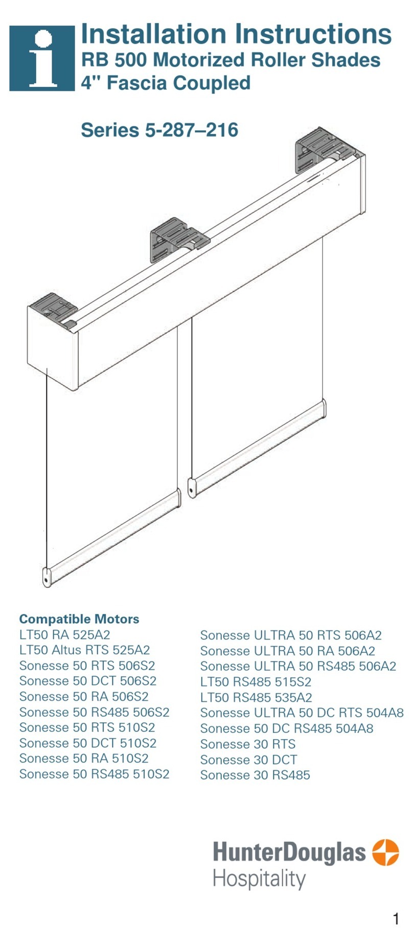
HunterDouglas RB 500 User manual

HunterDouglas

HunterDouglas RB 500 User manual
HunterDouglas Duette User manual

HunterDouglas

HunterDouglas Duette User manual

HunterDouglas Silhouette Assembly instructions

HunterDouglas

HunterDouglas Silhouette Assembly instructions

HunterDouglas Pirouette Parts list manual

HunterDouglas

HunterDouglas Pirouette Parts list manual

HunterDouglas Sonnette Parts list manual

HunterDouglas

HunterDouglas Sonnette Parts list manual

HunterDouglas Duette Owner's manual

HunterDouglas

HunterDouglas Duette Owner's manual

HunterDouglas Silhouette Parts list manual

HunterDouglas

HunterDouglas Silhouette Parts list manual

HunterDouglas Duette Parts list manual

HunterDouglas

HunterDouglas Duette Parts list manual

HunterDouglas Provenance Parts list manual

HunterDouglas

HunterDouglas Provenance Parts list manual

HunterDouglas Pirouette Installation manual

HunterDouglas

HunterDouglas Pirouette Installation manual

HunterDouglas Design Studio Roman Shades Straight-Pull... Parts list manual

HunterDouglas

HunterDouglas Design Studio Roman Shades Straight-Pull... Parts list manual

HunterDouglas Duette Owner's manual

HunterDouglas

HunterDouglas Duette Owner's manual

HunterDouglas Vignette Series Parts list manual

HunterDouglas

HunterDouglas Vignette Series Parts list manual

HunterDouglas Provenance Parts list manual

HunterDouglas

HunterDouglas Provenance Parts list manual

HunterDouglas Designer Parts list manual

HunterDouglas

HunterDouglas Designer Parts list manual

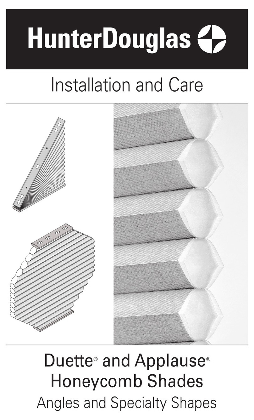
HunterDouglas Duette LightLock User manual

HunterDouglas

HunterDouglas Duette LightLock User manual

HunterDouglas Luminette PowerGlide 2.0 Assembly instructions

HunterDouglas

HunterDouglas Luminette PowerGlide 2.0 Assembly instructions

HunterDouglas Auto Stop User manual

HunterDouglas

HunterDouglas Auto Stop User manual

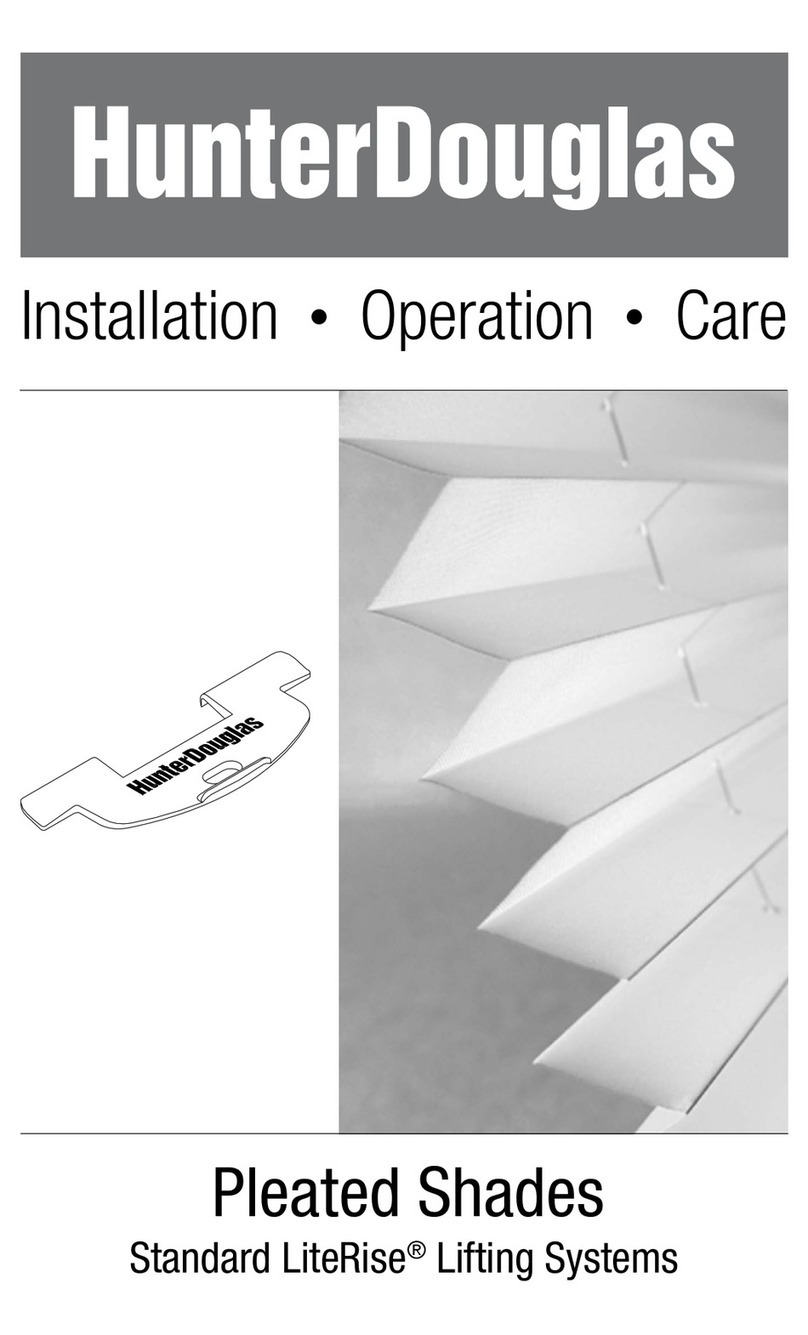
HunterDouglas Silhouette PowerView Parts list manual
HunterDouglas

HunterDouglas Silhouette PowerView Parts list manual

HunterDouglas Duette Parts list manual
HunterDouglas

HunterDouglas Duette Parts list manual
HunterDouglas Designer Screen Patio Shade Parts list manual

HunterDouglas

HunterDouglas Designer Screen Patio Shade Parts list manual

HunterDouglas Silhouette Installation manual

HunterDouglas

HunterDouglas Silhouette Installation manual

Popular Indoor Furnishing manuals by other brands

Bestar 88630-1169 Assembly instructions

Bestar

Bestar 88630-1169 Assembly instructions

Relax-A-Lounger SOFA Assembly instructions

Relax-A-Lounger

Relax-A-Lounger SOFA Assembly instructions

Triarch Indoor Lighting 33162 Assembly instructions

Triarch

Triarch Indoor Lighting 33162 Assembly instructions

Riverside Furniture Kara Occasional 13409 Assembly instructions

Riverside Furniture

Riverside Furniture Kara Occasional 13409 Assembly instructions

Tradecraft Specialties BULLDOZ-10 instruction manual

Tradecraft Specialties

Tradecraft Specialties BULLDOZ-10 instruction manual

Mobility TEK TEK88M instruction manual

Mobility TEK

Mobility TEK TEK88M instruction manual

Wickes Ohio 300 Assembly guide

Wickes

Wickes Ohio 300 Assembly guide

Freedom Archer Assembly instructions

Freedom

Freedom Archer Assembly instructions

TUHOME Furniture CLASSIC THREE DRAWER DRESSER Assembly instructions

TUHOME Furniture

TUHOME Furniture CLASSIC THREE DRAWER DRESSER Assembly instructions

SEI Waypoint HO731300TX Assembly instructions

SEI

SEI Waypoint HO731300TX Assembly instructions

PHI VILLA THD7-0604-116 Use and care guide

PHI VILLA

PHI VILLA THD7-0604-116 Use and care guide

Glacier bay Vanity Combo KHWHT48D Use and care guide

Glacier bay

Glacier bay Vanity Combo KHWHT48D Use and care guide

BLACK RED WHITE KASPIAN S128-RTV2D1S Assembly instructions

BLACK RED WHITE

BLACK RED WHITE KASPIAN S128-RTV2D1S Assembly instructions

Bush Business Furniture CH2701BLL-03 Assembly instructions

Bush Business Furniture

Bush Business Furniture CH2701BLL-03 Assembly instructions

Visionary MOD-1702 Setup instructions

Visionary

Visionary MOD-1702 Setup instructions

Seconique Athens Dining Table Assembly instructions

Seconique

Seconique Athens Dining Table Assembly instructions

J.Burrows JBACTMBMBK Assembly instructions

J.Burrows

J.Burrows JBACTMBMBK Assembly instructions

AON Archeus AON001BK Series Assembly guide

AON

AON Archeus AON001BK Series Assembly guide

manuals.online logo
manuals.online logoBrands
  • About & Mission
  • Contact us
  • Privacy Policy
  • Terms and Conditions

Copyright 2025 Manuals.Online. All Rights Reserved.