manuals.online logo
Brands
  1. Home
  2. •
  3. Brands
  4. •
  5. iDataLink
  6. •
  7. Automobile Accessories
  8. •
  9. iDataLink Maestro K150 User manual

iDataLink Maestro K150 User manual

QSG201503
QUICK
START
GUIDE
THIS
INSTALLATION
REQUIRES
AN
IDATALINK
MAESTRO
RR
MODULE
SOLD
SEPARATELY.
6
STEPS
TO
GET
STARTED
INSTALL
THE
WEB
LINK
PLUG-IN
Go
to:
idatalinkmaestro.com/plugin and
follow the installation steps.
Review
the
System
Requirements
before
instaWng.
REGISTER
A
WEBLINK
ACCOUNT
Go
to:
idatalinkmaestro.com/register and
complete the registration process.
A
confirmation
email
will
be
sent
to
you
requiring
validation.
CONNECT
YOUR
MAESJRO
RR
Use the included
USB
cable
ro
connect
your Maestro
RR
module to your
PC.
Maestro
RR
module
required
and
sold
separately.
NE
ED
HELP
?
\.
877.212
.
6169
/
Ttdl-ltol
'-
1.866.427.2'199
WE
BLINK
REGISTRATION
-
··-
··-
--
.,-:•..-,
_.._
~
.......
--..
..
.........
~
..
.__
-~·
·
-· -
...
-
o
-
~
--
WESUni'T
..
K15D
lOG
INTO
WEB
LINK
Go
to:
idatalinkmaestro.com/login.
Enter your username and
password, then click
OK.
PROGRAM
YOUR
MODULE
Follow
the installation ste1
ps
until your module
is
flashed and
download your insta
ll
guide from
the
Web.
Be
sure
to
choose
the
KJ
50
dash
kit
accessory
in
STEP
4.
COMPLETE
INSTALLA
T
ION
Follow
the steps
of
the install
guide for Maestro
RR
with
~
50
Dash Kit and complete the
installat
ion.
ADS
recommends
having
this
product
installed
by
a
certified
technician.
1
YEAR
LIMITED
WARRANTY
Automotive Data Solutions Inc. ("ADS"]
warrants
to the
original
purchaser
that
this
product
shall
be
free of
defects in
material
and
workmanship
under
normal
use and circumstances,
for
the period of one
(1]
year
as of the
original
date of purchase.
In
the event of any product
malfunction
during the Warranty period, the
original
purchaser
must
return
to the Authorized Dealer where it was
originally
purchased
with
the
original
proof of purchase. If a
malfunction
is detected, the Authorized Dealer
will
elect to
repair
or
replace the product at its discretion.
Labor
costs may
be
applicable and are at the discretion of the Authorized Dealer.
ADS
is not responsible
for
any damages whatsoever, including but not
limited
to any consequential
damages, incidental damages
for
loss of time, loss of earnings,
commercial
loss of economic
opportunity
and the like that may
or
may not have resulted
from
the
installation
or
operation of an iDatalink Maestro
product.
_
.........
,..
1·*-·--,
AUTOMOTIVE
DATA
SOLUTIONS
©Automotive
Data Solutions Inc.
~maestro
IDENTIFY
YOUR
MAESTRO
RR
VERSION
&
USE
THE
SPECIFIED
ACCESSORIES
IDENTIFIEZ
VOTRE
VERSION
DU
MAESTRO
RR
ET
UTILISEZ
LES
ACCESSOIRES
SPECIFIES
IDENTIFIOUE
SU
VERSION
DE
MAESTRO
RR
Y
USE
LOS
ACCESOR/OS
ESPECIFICADOS
MRR
v1.0
..•.......
3.
5
MM
C3
0
87
D
~
MRR256 1.0
YYYY-M
•.•••............•
...
••
.......••
......
.
.....
.......
.
.
.
.
.
.
.
.
.
.
.
.
.
.
.
.
f : :
--t
c--
;-J
- r - T
. .
. I
LOCATED
IN
THIS
BAG
INCLUS
DANS
CE
SAC
~
INCLU/00
EN
ESTA
BOLSA
MRR
v2.0
•••••••
•••
••
3-PIN
C3
0
870
~
MRR25 2.0
YYYY-M
LOCATED
WITH
HARNESS
IN
BOX
INCLU
AVEC
HARNA
IS
DANS
LA
BO
l
TE
~
INCLUIOO
CON
EL
ARNESEN
LA
CAJA
OEM
·
grade
fit
an~
finish
QuaUte
d'
assemblage
et
finltion
cl'orlgine
Calidad
de
mollfaje
yaabado
originates
Ergonomic
radio
positioning
for
easy
access
to
touchscreen
controls
Positionnement
ergonomique
de
Ia
radio
perr11et
un
acces
fac
i
le
a
votre
ecran
tactile
Ubicacidn
ergonomica
del
riilio
para
un
acceso
facil
a
Ia
pantatla
tJclil
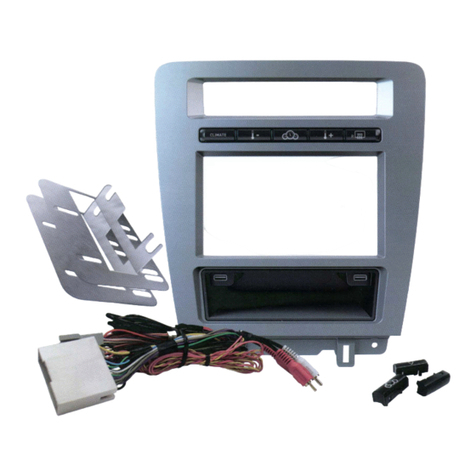
Convenient
storage
pocket
Pochette
de
rangement
pratique
Prictico
compartimento
paf8
otros
USIIS
AMde
toRf1Dl
dil
dimlfflador.
medidiJtfS.
~
delvebku/4yntis.
dirtetamen~
dsstJe
18
pll1#al/l
tidil
tl
uutJdfo
detDmbis
Adds
2x
USB
·
ports
,
1x
HDM1
-pitt
&
1x
3.5mm
port!
Ajoute
2
ports
USB
,1
port
HOMI
et
1
port
Umml
tAJilde
2
puertos
USB.
1
puerto
HO
HIy(
pwrta
3.5inml
OPTIONAL ACCESSORIES
None
PROGRAMMED FIRMWARE
ADS-RR(SR)-FO2-DS
PRODUCTS REQUIRED
iDatalink Maestro RR Radio Replacement Interface
iDatalink Maestro KIT-F150
INSTALL GUIDE
FORD F150
WITH MYFORD 4INCH SCREEN
20132014
retains steering wheel controls and more!
NOTICE: Automotive Data Solutions Inc. (ADS) recommends having this installation performed by a certified technician. Logos and trademarks used here
in are the properties of their respective owners.
ADS-RR(SR)-FO2-DS maestro.idatalink.com
Ford F150 2013-2014
Automotive Data Solutions Inc. © 2015 2
WELCOME
NEED HELP?
Congratulations on the purchase
of your iDatalink Maestro RR Radio
replacement solution. You are
now a few simple steps away from
enjoying your new car radio with
enhanced features.
Before starting your installation,
please ensure that your iDatalink
Maestro module is programmed
with the correct firmware and that
you carefully review the Installation
Diagram and Vehicle Wire Refer-
ence Chart.
Please note that Maestro RR will
only retain functionalities that
were originally available in the
vehicle.
1 866 427-2999
[email protected]
maestro.idatalink.com/support
www.12voltdata.com/forum
TABLE OF CONTENTS
Installation Instructions 3
Wiring Diagram 5
Radio Wire Reference Chart 6
ADS-RR(SR)-FO2-DS maestro.idatalink.com
Ford F150 2013-2014
Automotive Data Solutions Inc. © 2015 3
INSTALLATION INSTRUCTIONS
VEHICLE DASH DISASSEMBLY
STEP 1
• On passenger side of the vehicle, open the glove box and
push the side tabs toward each other to release glove box.
Extract (3) 8mm bolts to release the airbag. (1.1) (1.2)
STEP 2
• Without disconnecting the airbag, push it out far enough to
expose the copper-plated 7mm screw on the left side of the
airbag and extract it. (1.3)
STEP 3
• Remove the instrument cluster cover by removing (2) 7mm
screws. (1.4)
STEP 4
• Remove both side vent covers. (1.4)
STEP 5
• Remove the radio bezel by extracting (2) 7mm screws from
the top and (2) 7mm screws from the bottom. (1.5) (1.6)
STEP 6
• Remove (8) 7mm screws from the factory display and radio;
Remove both. (1.7)
STEP 7
• Remove the traction control button from the factory radio
bezel; It will be relocated to the K150 dash kit. (1.8)
1
Fig. 1.3
Fig. 1.5
Fig. 1.4
Fig. 1.6
Fig. 1.7 Fig. 1.8
Fig. 1.1 Fig. 1.2
A/C MAX
A/C
OFF
PASS
AIRBAG
OFF
Fig. 1.3
Fig. 1.5
Fig. 1.4
Fig. 1.6
Fig. 1.7 Fig. 1.8
Fig. 1.1 Fig. 1.2
A/C MAX
A/C
OFF
PASS
AIRBAG
OFF
ADS-RR(SR)-FO2-DS maestro.idatalink.com
Ford F150 2013-2014
Automotive Data Solutions Inc. © 2015 4
INSTALLATION INSTRUCTIONS
DASH KIT ASSEMBLY
STEP 8
• Unbox the K150 dash kit.
• Insert the factory traction control button into the K150 dash
kit. (2.1)
• Attach the storage pocket to the backside of the K150 dash
kit and secure it with the screws included in the kit. (2.2)
• Secure the K150 steel radio brackets to the aftermarket
radio using the screws included with the aftermarket radio.
(2.3)
CONNECTIONS (REFER TO DIAGRAM)
STEP 9
• Unbox the aftermarket radio and locate its main harness.
• Connect the wires from the aftermarket radio’s main
harness to the K150 T-harness and match the wire colors
(refer to diagram).
STEP 10
• Plug the aftermarket radio harnesses into the aftermarket
radio.
• Plug the Data cable to the data port of the aftermarket
radio (labeled iDatalink).
• Insert the Audio cable into the iDatalink 3.5 mm audio jack
of the aftermarket radio (labeled iDatalink).
NOTE:
In Pioneer radios: plug Audio cable in auxiliary input of
the radio.
• Plug the backup camera RCA cable into the aftermarket
radio (if applicable).
STEP 11
• Plug the aftermarket radio harnesses into the OBDII
connector, located under the driver side dashboard, and
run the wires up to the radio cavity.
STEP 12
• Connect the K150 T-harness to the factory radio harness.
• Plug the backup camera cable into the factory harness (if
applicable).
• Plug the HVAC cable in the factory harness.
STEP 13
• Insert the radio into the dash and secure the metal
brackets with the 7mm bolts removed during disassembly.
STEP 14
• Connect all the harnesses to the Maestro RR module.
STEP 15
• Connect all the harnesses to the K150 dash kit.
• Secure the K150 kit in the dash.
TROUBLESHOOTING TIPS:
• To reset the module back its factory settings, turn the key
to the OFF position then disconnect all connectors from
the module. Press and hold the module’s programming
button and connect all the connectors back to the module.
Wait, the module’s LED will flash RED rapidly (this may
take up to 10 seconds). Release the programming button.
Wait, the LED will turn solid GREEN for 2 seconds.
• For technical assistance call 1-866-427-2999 or e-mail
“[email protected]”. Visit us at “maestro.idatalink.
com/support” and “www.12voltdata.com/forum/”
1
Fig. 2.1
Fig. 2.3
Fig. 2.2
A/C MAX
A/C
OFF
PASS
AIRBAG
OFF
ADS-RR(SR)-FO2-DS maestro.idatalink.com
Ford F150 2013-2014
Automotive Data Solutions Inc. © 2015 5
Y
X
C
A
H
F
G
D
C
A
G
F
H
1
D
BACKUP CAMBACKUP CAM
Y
HVAC CABLE
STEP 15
WHITE - LF SPEAKER (+)
WHITE/BLACK - LF SPEAKER (-)
GRAY - RF SPEAKER (+)
GRAY/BLACK - RF SPEAKER (-)
GREEN - LR SPEAKER (+)
GREEN/BLACK - LR SPEAKER (-)
PURPLE/BLACK - RR SPEAKER (-)
YELLOW - 12V (+)
BLACK - GROUND
RED - ACCESSORY (+)
ORANGE - ILLUMINATION (+)
PURPLE/WHITE - REVERSE LIGHT (+)
LTGREEN - E-BRAKE (-)
BLUE/WHITE - AMP. TURN ON (+)
PURPLE - RR SPEAKER (+)
PINK - VEHICLE SPEED
YELLOW/BLACK - FOOT BRAKE
BROWN (NOT CONNECTED)
WIRES FROM
VEHICLE
MAIN
HARNESS
CONNECT TO
AFTERMARKET RADIO
RCA CABLE
FACTORY RADIO HARNESS
RR-F150 T-HARNESS
WIRING DIAGRAM
STEP 12
STEP 10
STEP 14
STEP 9
SEE RADIO
WIRE REFERENCE
CHART FOR
RADIO WIRE
COLORS
MAESTRO RR MODULE
DATA
CABLE
AUDIO
CABLE
STEP 11 OBDII CONNECTOR
ADS-RR(SR)-FO2-DS maestro.idatalink.com
Ford F150 2013-2014
Automotive Data Solutions Inc. © 2015 6
RADIO WIRE REFERENCE CHART
Wire
Description Polarity Wire Color on Maestro
T-Harness Wire Color on Alpine cable Wire Color on Kenwood cable Wire Color on Pioneer cable
Illumination (+) Orange N/A Orange/White Orange/White
Reverse Light (+) Purple/White Orange/White Purple/White Purple/White
E-Brake (-) Lt Green Yellow/Blue Lt Green Lt Green
Foot Brake (+) Yellow/Black Yellow/Black N/A N/A
VSS (vehicle speed sensor) (DATA) Pink Green/White N/A Pink
OPTIONAL ACCESSORIES
None
PROGRAMMED FIRMWARE
ADS-RR(SR)-FO2-AS
PRODUCTS REQUIRED
iDatalink Maestro RR Radio Replacement Interface
iDatalink Maestro KIT-F150
INSTALL GUIDE
FORD F150
WITH MYFORD 4INCH SCREEN
20132014
retains steering wheel controls and more!
NOTICE: Automotive Data Solutions Inc. (ADS) recommends having this installation performed by a certified technician. Logos and trademarks used here
in are the properties of their respective owners.
ADS-RR(SR)-FO2-AS maestro.idatalink.com
Ford F150 2013-2014
Automotive Data Solutions Inc. © 2015 2
WELCOME
NEED HELP?
Congratulations on the purchase
of your iDatalink Maestro RR Radio
replacement solution. You are
now a few simple steps away from
enjoying your new car radio with
enhanced features.
Before starting your installation,
please ensure that your iDatalink
Maestro module is programmed
with the correct firmware and that
you carefully review the Installation
Diagram and Vehicle Wire Refer-
ence Chart.
Please note that Maestro RR will
only retain functionalities that
were originally available in the
vehicle.
1 866 427-2999
[email protected]
maestro.idatalink.com/support
www.12voltdata.com/forum
TABLE OF CONTENTS
Installation Instructions 3
Wiring Diagram 5
Radio Wire Reference Chart 6
ADS-RR(SR)-FO2-AS maestro.idatalink.com
Ford F150 2013-2014
Automotive Data Solutions Inc. © 2015 3
INSTALLATION INSTRUCTIONS
VEHICLE DASH DISASSEMBLY
STEP 1
• On passenger side of the vehicle, open the glove box and
push the side tabs toward each other to release glove box.
Extract (3) 8mm bolts to release the airbag. (1.1) (1.2)
STEP 2
• Without disconnecting the airbag, push it out far enough to
expose the copper-plated 7mm screw on the left side of the
airbag and extract it. (1.3)
STEP 3
• Remove the instrument cluster cover by removing (2) 7mm
screws. (1.4)
STEP 4
• Remove both side vent covers. (1.4)
STEP 5
• Remove the radio bezel by extracting (2) 7mm screws from
the top and (2) 7mm screws from the bottom. (1.5) (1.6)
STEP 6
• Remove (8) 7mm screws from the factory display and radio;
Remove both. (1.7)
STEP 7
• Remove the traction control button from the factory radio
bezel; It will be relocated to the K150 dash kit. (1.8)
1
Fig. 1.3
Fig. 1.5
Fig. 1.4
Fig. 1.6
Fig. 1.7 Fig. 1.8
Fig. 1.1 Fig. 1.2
A/C MAX
A/C
OFF
PASS
AIRBAG
OFF
Fig. 1.3
Fig. 1.5
Fig. 1.4
Fig. 1.6
Fig. 1.7 Fig. 1.8
Fig. 1.1 Fig. 1.2
A/C MAX
A/C
OFF
PASS
AIRBAG
OFF
ADS-RR(SR)-FO2-AS maestro.idatalink.com
Ford F150 2013-2014
Automotive Data Solutions Inc. © 2015 4
INSTALLATION INSTRUCTIONS
DASH KIT ASSEMBLY
STEP 8
• Unbox the K150 dash kit.
• Insert the factory traction control button into the K150 dash
kit. (2.1)
• Attach the storage pocket to the backside of the K150 dash
kit and secure it with the screws included in the kit. (2.2)
• Secure the K150 steel radio brackets to the aftermarket
radio using the screws included with the aftermarket radio.
(2.3)
CONNECTIONS (REFER TO DIAGRAM)
STEP 9
• Unbox the aftermarket radio and locate its main harness.
• Connect the wires from the aftermarket radio’s main
harness to the K150 T-harness and match the wire colors
(refer to diagram).
STEP 10
• Plug the aftermarket radio harnesses into the aftermarket
radio.
• Connect the steering wheel control cable into the
aftermarket radio.
• Plug the backup camera RCA cable into the aftermarket
radio (if applicable).
STEP 11
• Connect the K150 T-harness to the factory radio harness.
• Plug the backup camera cable into the factory harness (if
applicable).
• Plug the HVAC cable in the factory harness.
STEP 12
• Insert the radio into the dash and secure the metal
brackets with the 7mm bolts removed during disassembly.
STEP 13
• Connect all the harnesses to the Maestro RR module.
STEP 14
• Connect all the harnesses to the K150 dash kit.
• Secure the K150 kit in the dash.
TROUBLESHOOTING TIPS:
• To reset the module back its factory settings, turn the key
to the OFF position then disconnect all connectors from
the module. Press and hold the module’s programming
button and connect all the connectors back to the module.
Wait, the module’s LED will flash RED rapidly (this may
take up to 10 seconds). Release the programming button.
Wait, the LED will turn solid GREEN for 2 seconds.
• For technical assistance call 1-866-427-2999 or e-mail
“[email protected]”. Visit us at “maestro.idatalink.
com/support” and “www.12voltdata.com/forum/”
1
Fig. 2.1
Fig. 2.3
Fig. 2.2
A/C MAX
A/C
OFF
PASS
AIRBAG
OFF
ADS-RR(SR)-FO2-AS maestro.idatalink.com
Ford F150 2013-2014
Automotive Data Solutions Inc. © 2015 5
Y
C
AF
G
X
C
A
G
F
1
BACKUP CAMBACKUP CAM
Y
E
E
HVAC CABLE
WHITE - LF SPEAKER (+)
WHITE/BLACK - LF SPEAKER (-)
GRAY - RF SPEAKER (+)
GRAY/BLACK - RF SPEAKER (-)
GREEN - LR SPEAKER (+)
GREEN/BLACK - LR SPEAKER (-)
PURPLE/BLACK - RR SPEAKER (-)
YELLOW - 12V (+)
BLACK - GROUND
RED - ACCESSORY (+)
ORANGE - ILLUMINATION (+)
PURPLE/WHITE - REVERSE LIGHT (+)
LTGREEN - E-BRAKE (-)
BLUE/WHITE - AMP. TURN ON (+)
PURPLE - RR SPEAKER (+)
PINK - VEHICLE SPEED
YELLOW/BLACK - FOOT BRAKE
BROWN (NOT CONNECTED)
(NOT CONNECTED)
(NOT CONNECTED)
WIRES FROM
VEHICLE
MAIN
HARNESS
RCA CABLE
FACTORY RADIO HARNESS
RR-F150 T-HARNESS
WIRING DIAGRAM
STEP 11
STEP 10
STEP 13
STEP 14
STEP 9
SEE RADIO
WIRE REFERENCE
CHART FOR
RADIO WIRE
COLORS
MAESTRO RR MODULE
CONNECT TO
AFTERMARKET RADIO
STEERING WHEEL
CONTROL CABLE
ADS-RR(SR)-FO2-AS maestro.idatalink.com
Ford F150 2013-2014
Automotive Data Solutions Inc. © 2015 6
RADIO WIRE REFERENCE CHART
Wire
Description Polarity Wire Color on Maestro
T-Harness Wire Color on Alpine cable Wire Color on Kenwood cable Wire Color on Pioneer cable
Illumination (+) Orange N/A Orange/White Orange/White
Reverse Light (+) Purple/White Orange/White Purple/White Purple/White
E-Brake (-) Lt Green Yellow/Blue Lt Green Lt Green
Foot Brake (+) Yellow/Black Yellow/Black N/A N/A
VSS (vehicle speed sensor) (DATA) Pink Green/White N/A Pink

This manual suits for next models

1

Other iDataLink Automobile Accessories manuals
iDataLink Maestro RR User manual

iDataLink

iDataLink Maestro RR User manual

iDataLink maestro Rr User manual

iDataLink

iDataLink maestro Rr User manual

iDataLink Maestro HRR-HO1 User manual

iDataLink

iDataLink Maestro HRR-HO1 User manual

iDataLink maestro Rr User manual

iDataLink

iDataLink maestro Rr User manual

iDataLink maestro Rr User manual

iDataLink

iDataLink maestro Rr User manual

iDataLink Maestro RR User manual

iDataLink

iDataLink Maestro RR User manual

iDataLink BLADE Series User manual

iDataLink

iDataLink BLADE Series User manual

iDataLink maestro Rr User manual

iDataLink

iDataLink maestro Rr User manual

iDataLink maestro Rr User manual

iDataLink

iDataLink maestro Rr User manual

iDataLink maestro Rr User manual

iDataLink

iDataLink maestro Rr User manual

iDataLink Maestro RR User manual

iDataLink

iDataLink Maestro RR User manual

iDataLink maestro mus1 User manual

iDataLink

iDataLink maestro mus1 User manual

iDataLink maestro Pr 2 User manual

iDataLink

iDataLink maestro Pr 2 User manual

iDataLink maestro Rr User manual

iDataLink

iDataLink maestro Rr User manual

iDataLink Maestro RR User manual

iDataLink

iDataLink Maestro RR User manual

iDataLink maestro Rr User manual

iDataLink

iDataLink maestro Rr User manual

iDataLink SUB9 User manual

iDataLink

iDataLink SUB9 User manual

iDataLink ADS-AL-CH4 User manual

iDataLink

iDataLink ADS-AL-CH4 User manual

iDataLink ADS-ALCA User manual

iDataLink

iDataLink ADS-ALCA User manual

iDataLink maestro Rr User manual

iDataLink

iDataLink maestro Rr User manual

iDataLink Maestro RR User manual

iDataLink

iDataLink Maestro RR User manual
iDataLink maestro Rr User manual

iDataLink

iDataLink maestro Rr User manual
iDataLink maestro Rr User manual

iDataLink

iDataLink maestro Rr User manual
iDataLink Maestro RR User manual

iDataLink

iDataLink Maestro RR User manual

Popular Automobile Accessories manuals by other brands

Whispbar K730W Fitting instructions

Whispbar

Whispbar K730W Fitting instructions

Camoplast Polaris TATOU 4S Installation guidelines

Camoplast

Camoplast Polaris TATOU 4S Installation guidelines

IFZ 1648298680 manual

IFZ

IFZ 1648298680 manual

aFe Power Scorpion instruction manual

aFe Power

aFe Power Scorpion instruction manual

AEM 22-436 installation instructions

AEM

AEM 22-436 installation instructions

Menabo PRO TOUR INDOOR Fitting instructions

Menabo

Menabo PRO TOUR INDOOR Fitting instructions

Menabo BIKI Fitting instructions

Menabo

Menabo BIKI Fitting instructions

gdw 1018 manual

gdw

gdw 1018 manual

Monoflex 03.6020 quick start guide

Monoflex

Monoflex 03.6020 quick start guide

Hebasto ThermoCall TC4 operating instructions

Hebasto

Hebasto ThermoCall TC4 operating instructions

Metra Electronics 99-8110 installation instructions

Metra Electronics

Metra Electronics 99-8110 installation instructions

Curt Manufacturing CM18153 installation instructions

Curt Manufacturing

Curt Manufacturing CM18153 installation instructions

Carr XRS Rota installation instructions

Carr

Carr XRS Rota installation instructions

MIRRORTAP MTX Series manual

MIRRORTAP

MIRRORTAP MTX Series manual

DEFA WarmUp Bluetooth Fitting instructions

DEFA

DEFA WarmUp Bluetooth Fitting instructions

Cruz Evo Rack E17-126 Assembly instructions

Cruz

Cruz Evo Rack E17-126 Assembly instructions

TEC Electronics CANTEC-F2 manual

TEC Electronics

TEC Electronics CANTEC-F2 manual

Acdeos AXS - FL Step manual

Acdeos

Acdeos AXS - FL Step manual

manuals.online logo
manuals.online logoBrands
  • About & Mission
  • Contact us
  • Privacy Policy
  • Terms and Conditions

Copyright 2025 Manuals.Online. All Rights Reserved.