ADS-RR(SI)-HON01-DS-IG-EN maestro.idatalink.comAutomotive Data Solutions Inc. © 2022 6
AcurA cSX with NAV 2009-2011
TROUBLESHOOTING TABLE
PROBLEM SOLUTION
Maestro features/steering wheel controls stop working after a few seconds. Ensure the GRAY/RED wire on the 18 pin connector of the RR is connected to
accessory power.
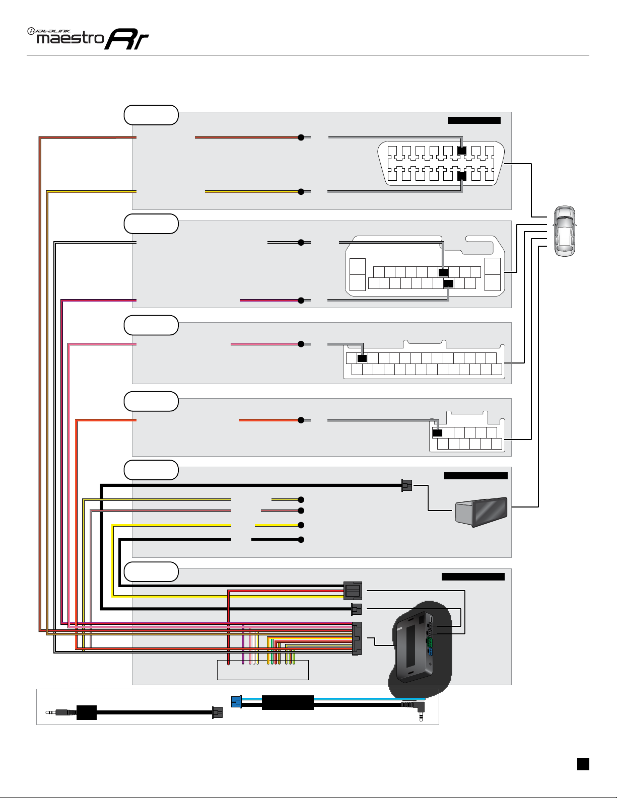
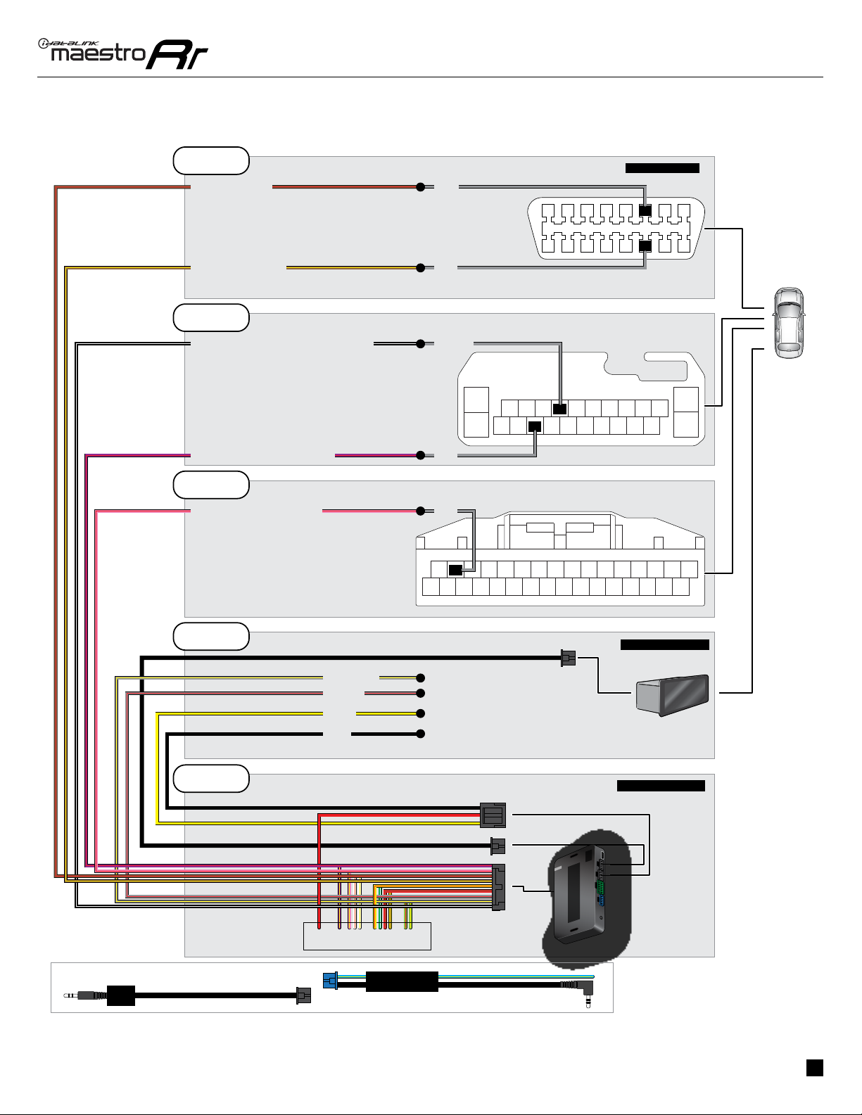
Gauges do not work, radio shows OBD2 Error 1 or Error 2. Ensure the BROWN/RED and BROWN/YELLOW wires are connected to the
OBDII (NOT the red/brown and yellow/brown wires).
Check connections at the OBDII connector. Make sure the BROWN/RED wire
is on PIN 6 and the BROWN/YELLOW wire is connected to PIN 14 of the
OBDII connector. Do not use T-Taps. Soldering or military splicing methods
are recommended.
Reset the RR.
The light on the Maestro is blinking RED TWICE. Ensure the 4-pin data cable is connected between the radio and the RR, and
that it is plugged into the black port on the Maestro RR. The red and blue
ports on the RR should be empty.
Make sure the correct radio model and serial number were entered during
the flash. Verify the radio’s serial number entered during the flash matches
what is listed on the radio screen. This can be found in the settings of the
radio, listed as Device Id, Device Number, or Serial Number.
The light on the Maestro is flashing RED once. There is no firmware on the module; flash the RR module.
MAESTRO RR RESET PROCEDURE:
Turn the key to the OFF position, then disconnect all connectors from the module.
Press and hold the module’s programming button and connect all the connectors back to the module. Wait, the module’s LED will flash RED rapidly (this may
take up to 10 seconds).
Release the programming button. Wait, the LED will turn solid GREEN for 2 seconds to show the reset was successful.
TECHNICAL ASSISTANCE
Phone: 1-866-427-2999
Web: maestro.idatalink.com/support add www.12voltdata.com/forum/
IMPORTANT: To ensure proper operation, the aftermarket radio needs to have the latest firmware from the manufacturer. Please visit the radio
manufacturer’s website and look for any updates pertaining to your radio.


-TL2 User manual")