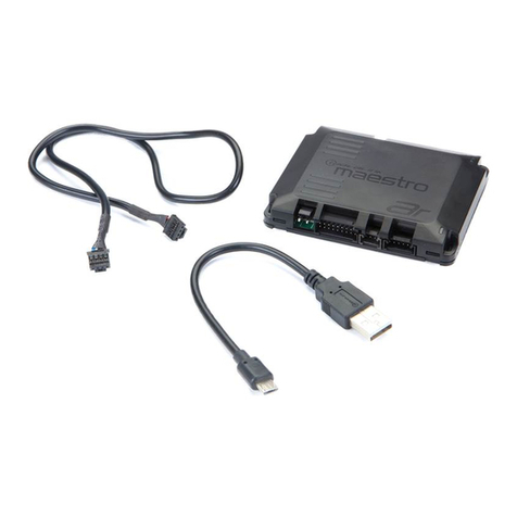
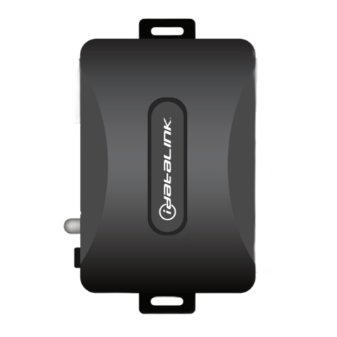
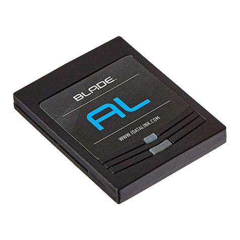
manuals.online logo
Brands
  1. Home
  2. •
  3. Brands
  4. •
  5. iDataLink
  6. •
  7. Automobile Accessories
  8. •
  9. iDataLink Maestro RR User manual

iDataLink Maestro RR User manual

NOTICE: Automotive Data Solutions Inc. (ADS) recommends having this installation performed by a certified technician. Logos and trademarks used here in
are the properties of their respective owners.
WARNING
Pressing the printer icon or “quick printing” this document will print
all of the guides in this compilation.
Open the Bookmarks menu and find your vehicle OR scroll
down until you find the install guide for your vehicle.
Print only the pages for your vehicle using the advanced
options in the Print menu.
Install your Maestro RR according to the guide for your vehicle.
HOW TO USE THIS INSTALL GUIDE
1
2
3
SELECT VEHICLE
PRINT PAGES NEEDED
2014-2022
Harley-DaviDson electra GliDe
INSTALL GUIDE
RETAINS HANDLE BAR CONTROLS
NOTICE: Automotive Data Solutions Inc. (ADS) recommends having this installation performed by a certified technician. Logos and trademarks used here
in are the properties of their respective owners.
PRODUCTS REQUIRED
iDatalink Maestro RR or RR2 Radio Replacement Interface
iDatalink Maestro HD2 Installation Harness
Non-iDatalink Compatible Radio
PROGRAMMED FIRMWARE
ADS-RR(SR)-HD02-DS
ADDITIONAL RESOURCES
Maestro RR2 Programmable Outputs Guide
OR
OPTIONAL ACCESSORIES
ACC-RR-WPB
ACC-ABP-HD2
ACC-USB-HD2
ADS-RR(SR)-HD02-DS-IG-EN maestro.idatalink.comAutomotive Data Solutions Inc. © 2022 2
Harley-DaviDson electra GliDe 2014-2022
NEED HELP?
TABLE OF CONTENTS
Installation Instructions 3
Wiring Diagram 4
Module Diagnostics 5
Troubleshooting Table 6
WELCOME
Congratulations on the purchase
of your iDatalink Maestro RR Radio
replacement solution. You are
now a few simple steps away from
enjoying your new car radio with
enhanced features.
Before starting your installation,
please ensure that your iDatalink
Maestro module is programmed
with the correct firmware for your
vehicle and that you carefully review
the install guide.
Please note that Maestro RR will
only retain functionalities that
were originally available in the
vehicle.
1 866 427-2999
maestro.idatalink.com/support
www.12voltdata.com/forum
[email protected]
ADS-RR(SR)-HD02-DS-IG-EN maestro.idatalink.comAutomotive Data Solutions Inc. © 2022 3
Harley-DaviDson electra GliDe 2014-2022
If retaining the OEM Amplifier:
• Before removing the factory radio, hold down the radio’s
mute/power button and turn the key ON (ignition switch on
the handlebars must also be ON).
• Keep holding the power button until the radio menus turn
orange; choose ‘accept’ and it will go into diagnostic menu
mode.
• Go to: Audio > EQ > Write down the 3-digit bin file number
for the EQ. You will need to enter this number once the new
radio is installed.
STEP 1
• Unbox the aftermarket radio and locate its main harness.
• Remove the factory radio.
• Cut and remove the RCA junction connectors. Connect
every wire from the aftermarket radio main harness to the
HD2 T-harness and match the wire functions.
Note: only connect purple/white wire to radio reverse input or
module damage will occur.
STEP 2
• Connect the HD2 T-harness to the vehicle.
STEP 3
• Plug the aftermarket radio harnesses into the aftermarket
radio.
• Plug the Data cable to the data port of the aftermarket
radio.
STEP 4
• Connect all the harnesses to the Maestro RR module then
test your installation.
To retain the OEM amplifier, enter the Bin EQ number from
the menus of the OEM radio:
• In the setup menu of the radio, go to: OEM Setup > Vehicle
Settings > Amp Settings > Audio System.
• Enter the Bin EQ number you got from the factory radio
menus one digit at a time, by tapping the number spaces
on the screen. Choose ‘Confirm’ and the bin EQ file will be
written to the system.
Note: Because the vehicle is not equipped with illumination
or reverse gear signals, these outputs can be triggered
manually by configuring them as steering wheel control
commands during the flashing process in Weblink.
1
INSTALLATION INSTRUCTIONS P1 /1
ADS-RR(SR)-HD02-DS-IG-EN maestro.idatalink.comAutomotive Data Solutions Inc. © 2022 4
Harley-DaviDson electra GliDe 2014-2022
1
MAIN
HARNESS
HD2 T-HARNESS
STEP 3
STEP 4
MAESTRO RR MODULE
WIRING DIAGRAM
WIRES FROM
VEHICLE
FACTORY RADIO HARNESS
STEP 2
AUDIO
CABLE
NOT REQUIRED
CONNECT TO
AFTERMARKET RADIO
DATA
CABLE
PIONEER RADIO:
ENSURE THAT NOTHING
IS PLUGGED IN W/R PORT.
STEERING WHEEL
CONTROL CABLE
CUT AND REMOVE
THE RCA JACKS
STEP 1
WHITE - LF SPEAKER (+)
WHITE/BLACK - LF SPEAKER (-)
GRAY - RF SPEAKER (+)
GRAY/BLACK - RF SPEAKER (-)
GREEN - LR SPEAKER (+)
GREEN/BLACK - LR SPEAKER (-)
PURPLE/BLACK - RR SPEAKER (-)
YELLOW - 12V (+)
BLACK - GROUND
RED - ACCESSORY (+)
BLUE/WHITE - AMP. TURN ON (+)
PURPLE - RR SPEAKER (+)
ORANGE - PARKING LIGHT (+)
PURPLE/WHITE - REVERSE LIGHT (+) *
LTGREEN - E-BRAKE (-)
PINK - VEHICLE SPEED
SEE RADIO WIRE
REFERENCE
CHART FOR
RADIO WIRE COLORS
* ONLY CONNECT TO RADIO REVERSE INPUT
OR MODULE DAMAGE WILL OCCUR
ADS-RR(SR)-HD02-DS-IG-EN maestro.idatalink.comAutomotive Data Solutions Inc. © 2022 5
Harley-DaviDson electra GliDe 2014-2022
MODULE DIAGNOSTICS
VIDEO HELP Installation, product information, vehicle specific videos.
VERIFY FLASH Last flash information, steering control configuration, vehicle information.
WEBLINK Software to program module.
LED 1 LED 2
LED 1
PROGRAMMING BUTTON
LED 1
Module/Firmware
status
LED 2 (RR2)
Bluetooth activity
LED STATUS DIAGNOSTIC
• or •RED or GREEN
flashing
LED flashes 1 or more times, either red or green, when a steering wheel
button is pressed : normal operation.
•1 RED flash Module has no firmware.
Flash module using Weblink Desktop and log in. Do NOT use DEMO MODE.
•2 RED flashes Problem detected. Consult troubleshooting table.
•1 GREEN flash After radio boots up : Normal operation.
•3 GREEN flashes Bluetooth is activated.
Turns off after one minute: Normal operation.
• • OFF Normal operation (inactive).
ADS-RR(SR)-HD02-DS-IG-EN maestro.idatalink.comAutomotive Data Solutions Inc. © 2022 6
Harley-DaviDson electra GliDe 2014-2022
TROUBLESHOOTING TABLE
PROBLEM SOLUTION
Sound is very quiet. Cut and remove the RCA connectors and connect the wires to the speaker
outputs of the radio.
The light on the Maestro is blinking RED TWICE. Ensure the 4-pin data cable is connected between the radio and the RR, and
that it is plugged into the black port on the Maestro RR. The red and blue
ports on the RR should be empty.
Make sure the correct radio model and serial number were entered during
the flash. Verify the radio’s serial number entered during the flash matches
what is listed on the radio screen. This can be found in the settings of the
radio, listed as Device Id, Device Number, or Serial Number.
The light on the Maestro is flashing RED ONCE. There is no firmware on the module; flash the RR module.
The audio quality is very bad. The Bin EQ number from the OEM radio may not be saved in the radio menu.
Enter the Bin EQ number from the OEM radio into the new radio's menus.
These menus are found in: OEM Setup > Vehicle Settings > Amp Settings >
Audio System.
MAESTRO RR RESET PROCEDURE:
Turn the key to the OFF position, then disconnect all connectors from the module.
Press and hold the module’s programming button and connect all the connectors back to the module. Wait, the module’s LED will flash RED rapidly (this may
take up to 10 seconds).
Release the programming button. Wait, the LED will turn solid GREEN for 2 seconds to show the reset was successful.
TECHNICAL ASSISTANCE
Phone: 1-866-427-2999
Email: maestr[email protected]
Web: maestro.idatalink.com/support add www.12voltdata.com/forum/
IMPORTANT: To ensure proper operation, the aftermarket radio needs to have the latest firmware from the manufacturer. Please visit the radio
manufacturer’s website and look for any updates pertaining to your radio.
2014-2022
Harley-DaviDson roaD GliDe
INSTALL GUIDE
RETAINS HANDLE BAR CONTROLS
NOTICE: Automotive Data Solutions Inc. (ADS) recommends having this installation performed by a certified technician. Logos and trademarks used here
in are the properties of their respective owners.
PRODUCTS REQUIRED
iDatalink Maestro RR or RR2 Radio Replacement Interface
iDatalink Maestro HD2 Installation Harness
Non-iDatalink Compatible Radio
PROGRAMMED FIRMWARE
ADS-RR(SR)-HD02-DS
ADDITIONAL RESOURCES
Maestro RR2 Programmable Outputs Guide
OR
OPTIONAL ACCESSORIES
ACC-RR-WPB
ACC-ABP-HD2
ACC-USB-HD2
ADS-RR(SR)-HD02-DS-IG-EN maestro.idatalink.comAutomotive Data Solutions Inc. © 2022 2
Harley-DaviDson roaD GliDe 2014-2022
NEED HELP?
TABLE OF CONTENTS
Installation Instructions 3
Wiring Diagram 4
Module Diagnostics 5
Troubleshooting Table 6
WELCOME
Congratulations on the purchase
of your iDatalink Maestro RR Radio
replacement solution. You are
now a few simple steps away from
enjoying your new car radio with
enhanced features.
Before starting your installation,
please ensure that your iDatalink
Maestro module is programmed
with the correct firmware for your
vehicle and that you carefully review
the install guide.
Please note that Maestro RR will
only retain functionalities that
were originally available in the
vehicle.
1 866 427-2999
maestro.idatalink.com/support
www.12voltdata.com/forum
[email protected]
ADS-RR(SR)-HD02-DS-IG-EN maestro.idatalink.comAutomotive Data Solutions Inc. © 2022 3
Harley-DaviDson roaD GliDe 2014-2022
If retaining the OEM Amplifier:
• Before removing the factory radio, hold down the radio’s
mute/power button and turn the key ON (ignition switch on
the handlebars must also be ON).
• Keep holding the power button until the radio menus turn
orange; choose ‘accept’ and it will go into diagnostic menu
mode.
• Go to: Audio > EQ > Write down the 3-digit bin file number
for the EQ. You will need to enter this number once the new
radio is installed.
STEP 1
• Unbox the aftermarket radio and locate its main harness.
• Remove the factory radio.
• Cut and remove the RCA junction connectors. Connect
every wire from the aftermarket radio main harness to the
HD2 T-harness and match the wire functions.
Note: only connect purple/white wire to radio reverse input or
module damage will occur.
STEP 2
• Connect the HD2 T-harness to the vehicle.
STEP 3
• Plug the aftermarket radio harnesses into the aftermarket
radio.
• Plug the Data cable to the data port of the aftermarket
radio.
STEP 4
• Connect all the harnesses to the Maestro RR module then
test your installation.
To retain the OEM amplifier, enter the Bin EQ number from
the menus of the OEM radio:
• In the setup menu of the radio, go to: OEM Setup > Vehicle
Settings > Amp Settings > Audio System.
• Enter the Bin EQ number you got from the factory radio
menus one digit at a time, by tapping the number spaces
on the screen. Choose ‘Confirm’ and the bin EQ file will be
written to the system.
Note: Because the vehicle is not equipped with illumination
or reverse gear signals, these outputs can be triggered
manually by configuring them as steering wheel control
commands during the flashing process in Weblink.
1
INSTALLATION INSTRUCTIONS P1 /1
ADS-RR(SR)-HD02-DS-IG-EN maestro.idatalink.comAutomotive Data Solutions Inc. © 2022 4
Harley-DaviDson roaD GliDe 2014-2022
1
MAIN
HARNESS
HD2 T-HARNESS
STEP 3
STEP 4
MAESTRO RR MODULE
WIRING DIAGRAM
WIRES FROM
VEHICLE
FACTORY RADIO HARNESS
STEP 2
AUDIO
CABLE
NOT REQUIRED
CONNECT TO
AFTERMARKET RADIO
DATA
CABLE
PIONEER RADIO:
ENSURE THAT NOTHING
IS PLUGGED IN W/R PORT.
STEERING WHEEL
CONTROL CABLE
CUT AND REMOVE
THE RCA JACKS
STEP 1
WHITE - LF SPEAKER (+)
WHITE/BLACK - LF SPEAKER (-)
GRAY - RF SPEAKER (+)
GRAY/BLACK - RF SPEAKER (-)
GREEN - LR SPEAKER (+)
GREEN/BLACK - LR SPEAKER (-)
PURPLE/BLACK - RR SPEAKER (-)
YELLOW - 12V (+)
BLACK - GROUND
RED - ACCESSORY (+)
BLUE/WHITE - AMP. TURN ON (+)
PURPLE - RR SPEAKER (+)
ORANGE - PARKING LIGHT (+)
PURPLE/WHITE - REVERSE LIGHT (+) *
LTGREEN - E-BRAKE (-)
PINK - VEHICLE SPEED
SEE RADIO WIRE
REFERENCE
CHART FOR
RADIO WIRE COLORS
* ONLY CONNECT TO RADIO REVERSE INPUT
OR MODULE DAMAGE WILL OCCUR
ADS-RR(SR)-HD02-DS-IG-EN maestro.idatalink.comAutomotive Data Solutions Inc. © 2022 5
Harley-DaviDson roaD GliDe 2014-2022
MODULE DIAGNOSTICS
VIDEO HELP Installation, product information, vehicle specific videos.
VERIFY FLASH Last flash information, steering control configuration, vehicle information.
WEBLINK Software to program module.
LED 1 LED 2
LED 1
PROGRAMMING BUTTON
LED 1
Module/Firmware
status
LED 2 (RR2)
Bluetooth activity
LED STATUS DIAGNOSTIC
• or •RED or GREEN
flashing
LED flashes 1 or more times, either red or green, when a steering wheel
button is pressed : normal operation.
•1 RED flash Module has no firmware.
Flash module using Weblink Desktop and log in. Do NOT use DEMO MODE.
•2 RED flashes Problem detected. Consult troubleshooting table.
•1 GREEN flash After radio boots up : Normal operation.
•3 GREEN flashes Bluetooth is activated.
Turns off after one minute: Normal operation.
• • OFF Normal operation (inactive).
ADS-RR(SR)-HD02-DS-IG-EN maestro.idatalink.comAutomotive Data Solutions Inc. © 2022 6
Harley-DaviDson roaD GliDe 2014-2022
TROUBLESHOOTING TABLE
PROBLEM SOLUTION
Sound is very quiet. Cut and remove the RCA connectors and connect the wires to the speaker
outputs of the radio.
The light on the Maestro is blinking RED TWICE. Ensure the 4-pin data cable is connected between the radio and the RR, and
that it is plugged into the black port on the Maestro RR. The red and blue
ports on the RR should be empty.
Make sure the correct radio model and serial number were entered during
the flash. Verify the radio’s serial number entered during the flash matches
what is listed on the radio screen. This can be found in the settings of the
radio, listed as Device Id, Device Number, or Serial Number.
The light on the Maestro is flashing RED ONCE. There is no firmware on the module; flash the RR module.
The audio quality is very bad. The Bin EQ number from the OEM radio may not be saved in the radio menu.
Enter the Bin EQ number from the OEM radio into the new radio's menus.
These menus are found in: OEM Setup > Vehicle Settings > Amp Settings >
Audio System.
MAESTRO RR RESET PROCEDURE:
Turn the key to the OFF position, then disconnect all connectors from the module.
Press and hold the module’s programming button and connect all the connectors back to the module. Wait, the module’s LED will flash RED rapidly (this may
take up to 10 seconds).
Release the programming button. Wait, the LED will turn solid GREEN for 2 seconds to show the reset was successful.
TECHNICAL ASSISTANCE
Phone: 1-866-427-2999
Email: maestr[email protected]
Web: maestro.idatalink.com/support add www.12voltdata.com/forum/
IMPORTANT: To ensure proper operation, the aftermarket radio needs to have the latest firmware from the manufacturer. Please visit the radio
manufacturer’s website and look for any updates pertaining to your radio.
2014-2022
Harley-DaviDson street GliDe
INSTALL GUIDE
RETAINS HANDLE BAR CONTROLS
NOTICE: Automotive Data Solutions Inc. (ADS) recommends having this installation performed by a certified technician. Logos and trademarks used here
in are the properties of their respective owners.
PRODUCTS REQUIRED
iDatalink Maestro RR or RR2 Radio Replacement Interface
iDatalink Maestro HD2 Installation Harness
Non-iDatalink Compatible Radio
PROGRAMMED FIRMWARE
ADS-RR(SR)-HD02-DS
ADDITIONAL RESOURCES
Maestro RR2 Programmable Outputs Guide
OR
OPTIONAL ACCESSORIES
ACC-RR-WPB
ACC-ABP-HD2
ACC-USB-HD2
ADS-RR(SR)-HD02-DS-IG-EN maestro.idatalink.comAutomotive Data Solutions Inc. © 2022 2
Harley-DaviDson street GliDe 2014-2022
NEED HELP?
TABLE OF CONTENTS
Installation Instructions 3
Wiring Diagram 4
Module Diagnostics 5
Troubleshooting Table 6
WELCOME
Congratulations on the purchase
of your iDatalink Maestro RR Radio
replacement solution. You are
now a few simple steps away from
enjoying your new car radio with
enhanced features.
Before starting your installation,
please ensure that your iDatalink
Maestro module is programmed
with the correct firmware for your
vehicle and that you carefully review
the install guide.
Please note that Maestro RR will
only retain functionalities that
were originally available in the
vehicle.
1 866 427-2999
maestro.idatalink.com/support
www.12voltdata.com/forum
[email protected]
ADS-RR(SR)-HD02-DS-IG-EN maestro.idatalink.comAutomotive Data Solutions Inc. © 2022 3
Harley-DaviDson street GliDe 2014-2022
If retaining the OEM Amplifier:
• Before removing the factory radio, hold down the radio’s
mute/power button and turn the key ON (ignition switch on
the handlebars must also be ON).
• Keep holding the power button until the radio menus turn
orange; choose ‘accept’ and it will go into diagnostic menu
mode.
• Go to: Audio > EQ > Write down the 3-digit bin file number
for the EQ. You will need to enter this number once the new
radio is installed.
STEP 1
• Unbox the aftermarket radio and locate its main harness.
• Remove the factory radio.
• Cut and remove the RCA junction connectors. Connect
every wire from the aftermarket radio main harness to the
HD2 T-harness and match the wire functions.
Note: only connect purple/white wire to radio reverse input or
module damage will occur.
STEP 2
• Connect the HD2 T-harness to the vehicle.
STEP 3
• Plug the aftermarket radio harnesses into the aftermarket
radio.
• Plug the Data cable to the data port of the aftermarket
radio.
STEP 4
• Connect all the harnesses to the Maestro RR module then
test your installation.
To retain the OEM amplifier, enter the Bin EQ number from
the menus of the OEM radio:
• In the setup menu of the radio, go to: OEM Setup > Vehicle
Settings > Amp Settings > Audio System.
• Enter the Bin EQ number you got from the factory radio
menus one digit at a time, by tapping the number spaces
on the screen. Choose ‘Confirm’ and the bin EQ file will be
written to the system.
Note: Because the vehicle is not equipped with illumination
or reverse gear signals, these outputs can be triggered
manually by configuring them as steering wheel control
commands during the flashing process in Weblink.
1
INSTALLATION INSTRUCTIONS P1 /1
ADS-RR(SR)-HD02-DS-IG-EN maestro.idatalink.comAutomotive Data Solutions Inc. © 2022 4
Harley-DaviDson street GliDe 2014-2022
1
MAIN
HARNESS
HD2 T-HARNESS
STEP 3
STEP 4
MAESTRO RR MODULE
WIRING DIAGRAM
WIRES FROM
VEHICLE
FACTORY RADIO HARNESS
STEP 2
AUDIO
CABLE
NOT REQUIRED
CONNECT TO
AFTERMARKET RADIO
DATA
CABLE
PIONEER RADIO:
ENSURE THAT NOTHING
IS PLUGGED IN W/R PORT.
STEERING WHEEL
CONTROL CABLE
CUT AND REMOVE
THE RCA JACKS
STEP 1
WHITE - LF SPEAKER (+)
WHITE/BLACK - LF SPEAKER (-)
GRAY - RF SPEAKER (+)
GRAY/BLACK - RF SPEAKER (-)
GREEN - LR SPEAKER (+)
GREEN/BLACK - LR SPEAKER (-)
PURPLE/BLACK - RR SPEAKER (-)
YELLOW - 12V (+)
BLACK - GROUND
RED - ACCESSORY (+)
BLUE/WHITE - AMP. TURN ON (+)
PURPLE - RR SPEAKER (+)
ORANGE - PARKING LIGHT (+)
PURPLE/WHITE - REVERSE LIGHT (+) *
LTGREEN - E-BRAKE (-)
PINK - VEHICLE SPEED
SEE RADIO WIRE
REFERENCE
CHART FOR
RADIO WIRE COLORS
* ONLY CONNECT TO RADIO REVERSE INPUT
OR MODULE DAMAGE WILL OCCUR
ADS-RR(SR)-HD02-DS-IG-EN maestro.idatalink.comAutomotive Data Solutions Inc. © 2022 5
Harley-DaviDson street GliDe 2014-2022
MODULE DIAGNOSTICS
VIDEO HELP Installation, product information, vehicle specific videos.
VERIFY FLASH Last flash information, steering control configuration, vehicle information.
WEBLINK Software to program module.
LED 1 LED 2
LED 1
PROGRAMMING BUTTON
LED 1
Module/Firmware
status
LED 2 (RR2)
Bluetooth activity
LED STATUS DIAGNOSTIC
• or •RED or GREEN
flashing
LED flashes 1 or more times, either red or green, when a steering wheel
button is pressed : normal operation.
•1 RED flash Module has no firmware.
Flash module using Weblink Desktop and log in. Do NOT use DEMO MODE.
•2 RED flashes Problem detected. Consult troubleshooting table.
•1 GREEN flash After radio boots up : Normal operation.
•3 GREEN flashes Bluetooth is activated.
Turns off after one minute: Normal operation.
• • OFF Normal operation (inactive).
ADS-RR(SR)-HD02-DS-IG-EN maestro.idatalink.comAutomotive Data Solutions Inc. © 2022 6
Harley-DaviDson street GliDe 2014-2022
TROUBLESHOOTING TABLE
PROBLEM SOLUTION
Sound is very quiet. Cut and remove the RCA connectors and connect the wires to the speaker
outputs of the radio.
The light on the Maestro is blinking RED TWICE. Ensure the 4-pin data cable is connected between the radio and the RR, and
that it is plugged into the black port on the Maestro RR. The red and blue
ports on the RR should be empty.
Make sure the correct radio model and serial number were entered during
the flash. Verify the radio’s serial number entered during the flash matches
what is listed on the radio screen. This can be found in the settings of the
radio, listed as Device Id, Device Number, or Serial Number.
The light on the Maestro is flashing RED ONCE. There is no firmware on the module; flash the RR module.
The audio quality is very bad. The Bin EQ number from the OEM radio may not be saved in the radio menu.
Enter the Bin EQ number from the OEM radio into the new radio's menus.
These menus are found in: OEM Setup > Vehicle Settings > Amp Settings >
Audio System.
MAESTRO RR RESET PROCEDURE:
Turn the key to the OFF position, then disconnect all connectors from the module.
Press and hold the module’s programming button and connect all the connectors back to the module. Wait, the module’s LED will flash RED rapidly (this may
take up to 10 seconds).
Release the programming button. Wait, the LED will turn solid GREEN for 2 seconds to show the reset was successful.
TECHNICAL ASSISTANCE
Phone: 1-866-427-2999
Email: maestr[email protected]
Web: maestro.idatalink.com/support add www.12voltdata.com/forum/
IMPORTANT: To ensure proper operation, the aftermarket radio needs to have the latest firmware from the manufacturer. Please visit the radio
manufacturer’s website and look for any updates pertaining to your radio.
2014-2022
Harley-DaviDson tri GliDe
INSTALL GUIDE
RETAINS HANDLE BAR CONTROLS
NOTICE: Automotive Data Solutions Inc. (ADS) recommends having this installation performed by a certified technician. Logos and trademarks used here
in are the properties of their respective owners.
PRODUCTS REQUIRED
iDatalink Maestro RR or RR2 Radio Replacement Interface
iDatalink Maestro HD2 Installation Harness
Non-iDatalink Compatible Radio
PROGRAMMED FIRMWARE
ADS-RR(SR)-HD02-DS
ADDITIONAL RESOURCES
Maestro RR2 Programmable Outputs Guide
OR
OPTIONAL ACCESSORIES
ACC-RR-WPB
ACC-ABP-HD2
ACC-USB-HD2

Other manuals for Maestro RR

12

Other iDataLink Automobile Accessories manuals

iDataLink maestro Rr User manual

iDataLink

iDataLink maestro Rr User manual

iDataLink maestro Rr User manual

iDataLink

iDataLink maestro Rr User manual

iDataLink maestro SW User manual

iDataLink

iDataLink maestro SW User manual

iDataLink Maestro K150 User manual

iDataLink

iDataLink Maestro K150 User manual

iDataLink Maestro RR User manual

iDataLink

iDataLink Maestro RR User manual

iDataLink Maestro HRR-HO1 User manual

iDataLink

iDataLink Maestro HRR-HO1 User manual

iDataLink Maestro RR User manual

iDataLink

iDataLink Maestro RR User manual

iDataLink maestro Rr User manual

iDataLink

iDataLink maestro Rr User manual

iDataLink Maestro RR User manual

iDataLink

iDataLink Maestro RR User manual

iDataLink maestro Rr User manual

iDataLink

iDataLink maestro Rr User manual

iDataLink ADS-TBSL-C1 User manual

iDataLink

iDataLink ADS-TBSL-C1 User manual

iDataLink maestro Rr User manual

iDataLink

iDataLink maestro Rr User manual

iDataLink maestro Rr User manual

iDataLink

iDataLink maestro Rr User manual

iDataLink maestro Rr User manual

iDataLink

iDataLink maestro Rr User manual

iDataLink maestro Pr 2 User manual

iDataLink

iDataLink maestro Pr 2 User manual

iDataLink maestro Rr User manual

iDataLink

iDataLink maestro Rr User manual

iDataLink BLADE Series User manual

iDataLink

iDataLink BLADE Series User manual

iDataLink ADS-ALCA User manual

iDataLink

iDataLink ADS-ALCA User manual

iDataLink BLADE-AL-HK4-EN User manual

iDataLink

iDataLink BLADE-AL-HK4-EN User manual

iDataLink maestro Rr User manual

iDataLink

iDataLink maestro Rr User manual

iDataLink ADS-ALCA User manual

iDataLink

iDataLink ADS-ALCA User manual

iDataLink maestro Rr User manual

iDataLink

iDataLink maestro Rr User manual

iDataLink maestro Rr User manual

iDataLink

iDataLink maestro Rr User manual

iDataLink Maestro RR User manual

iDataLink

iDataLink Maestro RR User manual
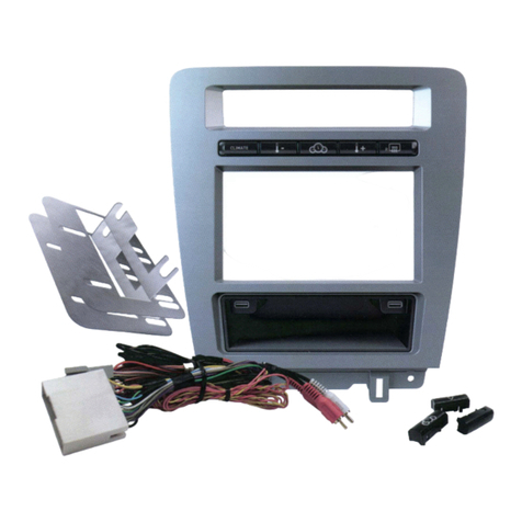
Popular Automobile Accessories manuals by other brands

STO N SHO Big Mike's Performance Parts SNS 60 Installation procedures

STO N SHO

STO N SHO Big Mike's Performance Parts SNS 60 Installation procedures

Bilstein 4600 Series Mounting instruction

Bilstein

Bilstein 4600 Series Mounting instruction

Rugged Ridge 11232.09 manual

Rugged Ridge

Rugged Ridge 11232.09 manual

CrimeStopper CS-5502 Wiring instruction

CrimeStopper

CrimeStopper CS-5502 Wiring instruction

Safe Fleet RVS systems RVS-M641 instruction manual

Safe Fleet

Safe Fleet RVS systems RVS-M641 instruction manual

Swagman 64685 instruction sheet

Swagman

Swagman 64685 instruction sheet

Safe Fleet PRIME DESIGN VRR3-PC11B Assembly instructions

Safe Fleet

Safe Fleet PRIME DESIGN VRR3-PC11B Assembly instructions

Whelen Engineering Company SA315 installation guide

Whelen Engineering Company

Whelen Engineering Company SA315 installation guide

Quikcell DRIVE DOCK quick start guide

Quikcell

Quikcell DRIVE DOCK quick start guide

Whelen Engineering Company 400 Series installation guide

Whelen Engineering Company

Whelen Engineering Company 400 Series installation guide

Dynojet Power commander V installation guide

Dynojet

Dynojet Power commander V installation guide

Kuda-Phonebase 284300 installation instructions

Kuda-Phonebase

Kuda-Phonebase 284300 installation instructions

Kolpin Outdoors 2738 Product instructions

Kolpin Outdoors

Kolpin Outdoors 2738 Product instructions

Diehl IZAR RECEIVER BT installation guide

Diehl

Diehl IZAR RECEIVER BT installation guide

AUSSIE TONNEAU ATR01155 FITTING INSTRUCTION

AUSSIE TONNEAU

AUSSIE TONNEAU ATR01155 FITTING INSTRUCTION

PROF SVAR TMB PS 047 User's guide and installation instructions

PROF SVAR

PROF SVAR TMB PS 047 User's guide and installation instructions

AMP Research Power Step installation guide

AMP Research

AMP Research Power Step installation guide

Thule FreeRide 532 installation instructions

Thule

Thule FreeRide 532 installation instructions

manuals.online logo
manuals.online logoBrands
  • About & Mission
  • Contact us
  • Privacy Policy
  • Terms and Conditions

Copyright 2025 Manuals.Online. All Rights Reserved.