ADS-RR(SR)-DUR1-DS-IG-EN maestro.idatalink.com
DoDge Durango 2014-2017
Automotive Data Solutions Inc. © 2019 4
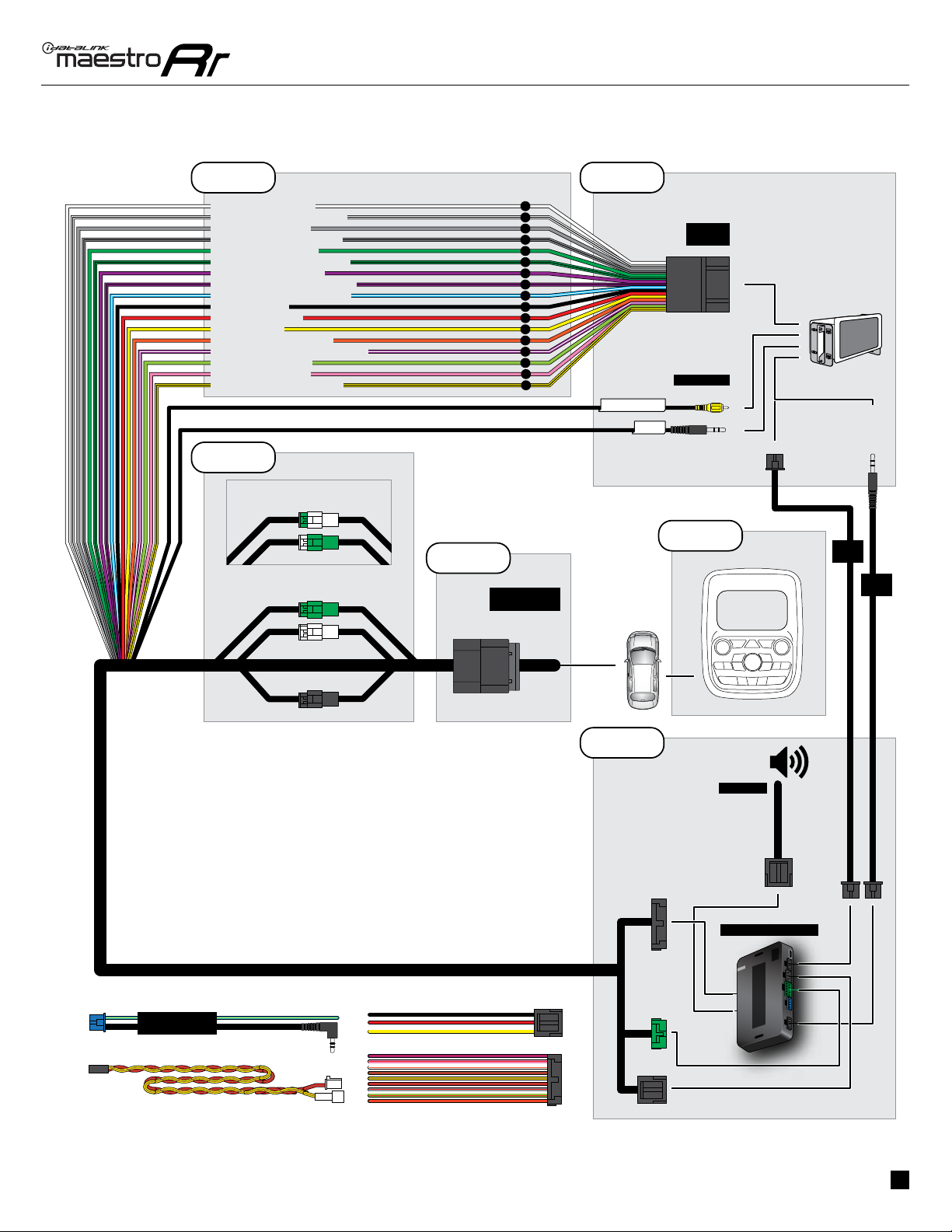
Fig. 2.0
INSTALLATION INSTRUCTIONS
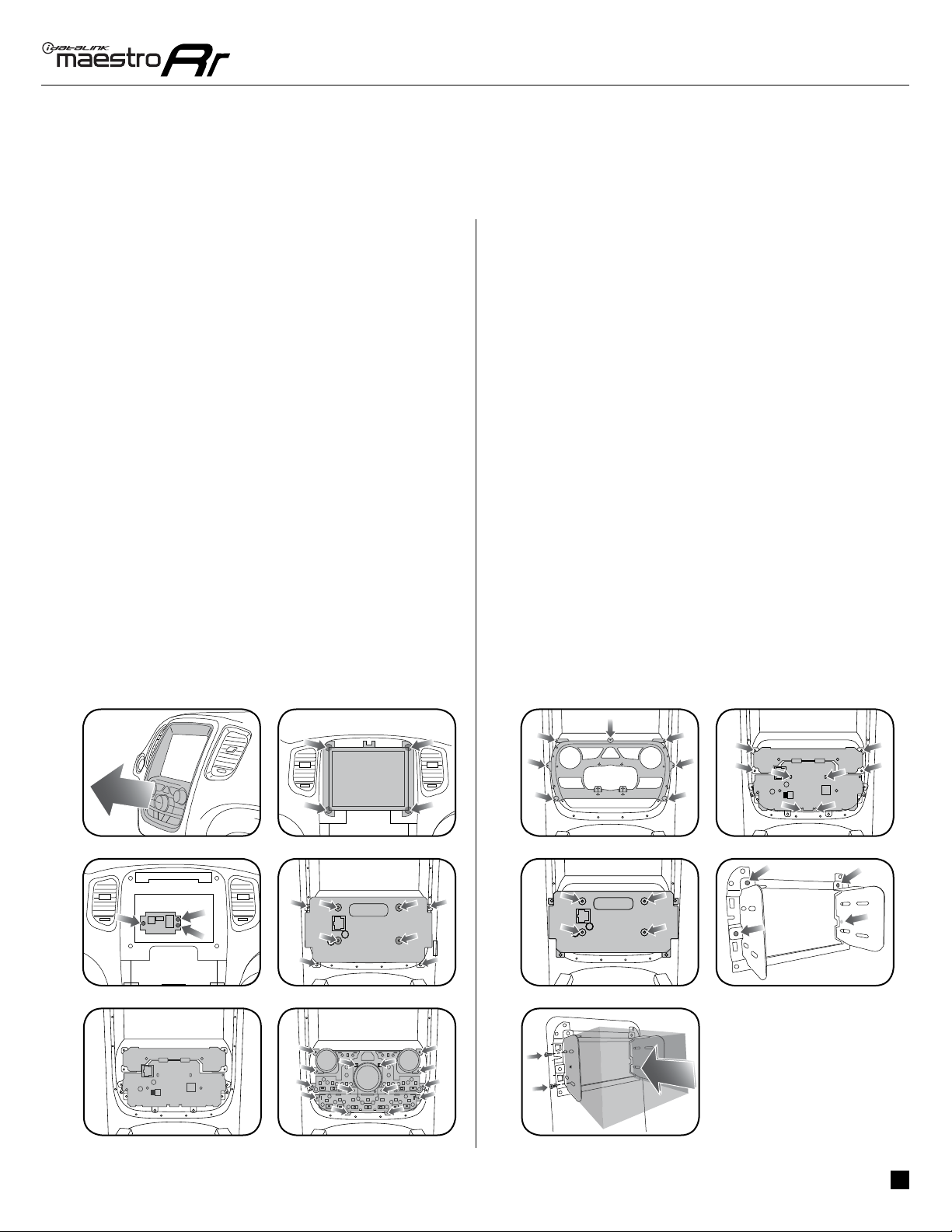
MEDIA PORT REPLACEMENT
• Pry the center console/shifter bezel upward. Disconnect
and remove.
• Remove the OEM media port by removing (4) torx screws.
Install the supplied media port and reassemble.
MAKE CONNECTIONS (refer to wiring diagram)
STEP 1
• Unbox the aftermarket radio and locate its main harness.
• Connect the wires shown on the next page from
aftermarket radio main harness to the DUR1 T-harness
and match the wire functions.
STEP 2
• Determine if the vehicle has a factory amplifier. Look for
badges on the door panels and dash that indicate the
presence of an amplifier (ex: Alpine).
If the vehicle DOES NOT have a factory amplifier:
• Plug the female GREEN connector to the male GREEN
connector of your DUR1 T-harness.
• Plug the female WHITE connector to the male WHITE
connector of your DUR1 T-harness.
If the vehicle DOES have a factory amplifier:
• Plug the female GREEN connector to the male WHITE
connector of your DUR1 T-harness.
• Plug the female WHITE connector to the male GREEN
connector of your DUR1 T-harness.
STEP 3
• Connect the factory harness to the DUR1 T-harness.
STEP 4
• Plug the aftermarket radio harnesses into the aftermarket
radio.
• Plug the backup camera RCA into the aftermarket radio (if
applicable).
• Plug the RSE cable into the aftermarket radio (AV in).
• Plug the Data cable to the data port of the aftermarket
radio.
• Insert the Audio cable into the iDatalink 3.5 mm audio jack
of the aftermarket radio.
NOTE:
Note: When using a Pioneer radio, please ensure that
there is nothing plugged into the W/R port of the radio.
STEP 5
• Connect all the harnesses to the Maestro RR module then
test your installation.
• If the vehicle is equipped with OEM parking assist, lane
departure, or other safety systems, the ADS-SP1 is
required: Plug the ADS-SP1 the Maestro RR.
If you are not using this speaker, the radio will mute when
the parking assist is active. If you are using this speaker,
the parking assist chimes will play through the external
speaker and the radio will not mute unless the settings
are changed in the radio.
STEP 6
• Install the aftermarket radio and DUR1 kit into the dash,
then test your installation.
1