ADS-RR(SR)-MA2H-DS-IG-EN maestro.idatalink.comAutomotive Data Solutions Inc. © 2023 3
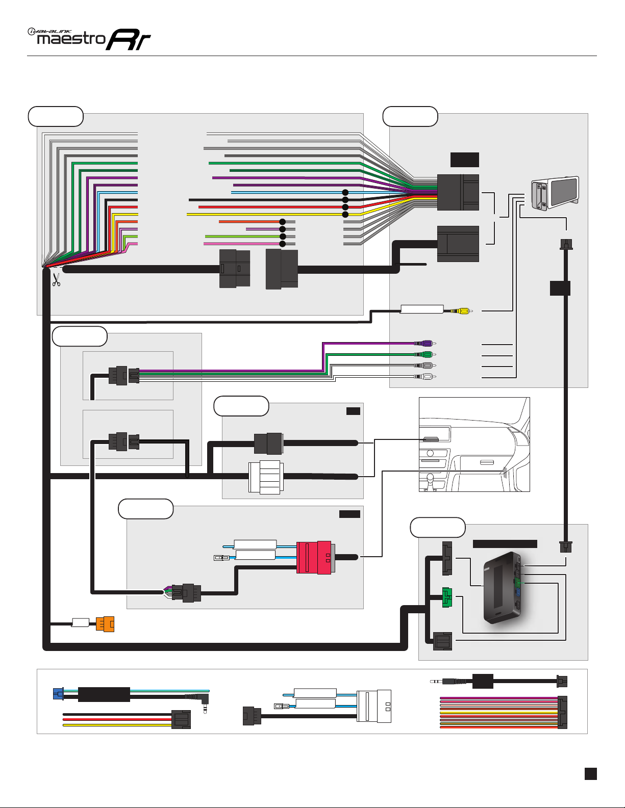
MAZDA 3 TOUCHSCREEN 20142017
STEP 1
• Disconnect the negative battery terminal (not doing so
may blow the 7.5A audio fuse 2 under hood during the
installation of the radio).
• Remove the factory radio
If using head unit adapter (sold separately), connect HRR-
MA2 harness to adapter and skip to step 2.
• Unbox the aftermarket radio and locate its main harness.
• Cut and remove the black 20 pin connector from the HRR-
MA2 T-harness and connect the wires, shown in the wiring
diagram, from aftermarket radio main harness to the HRR-
MA2 T-harness and match the wire functions.
Note: only connect purple/white wire to radio reverse input
or module damage will occur.
STEP 2
If the vehicle DOES NOT have a factory amplifier:
• Plug in the extension harness to HRR-MA2 main harness
8-pin black connector.
If the vehicle DOES have a factory amplifier:
• Plug in the extension harness to 8-pin black connector of
RCA cable.
• Connect the RCAs to the radio outputs: white/left front,
gray/right front, green/left rear, purple/right rear.
• Route the extension harness to the radio tuner in the
passenger kick panel.
STEP 3
• Connect both the 18-pin and 28-pin connectors of HRR-
MA2 T-harness to the factory radio harness (at CMU,
behind/below display).
STEP 4
• Connect the 24-pin adapter (red connector) to the factory
radio tuner in the passenger kick panel.
• Connect the adapter’s 8-pin black connector to the
extension harness.
• Plug the blue POWER ANT terminal to amplified antenna
adapter (if required).
STEP 5
• Plug the harnesses into the aftermarket radio.
• Connect the backup cam cable into the aftermarket radio
(if equipped).
• Plug the antenna adapter (if required).
• Plug the Data cable to the data port of the aftermarket
radio.
Note: On Pioneer radio, ensure that there is nothing plugged
into the W/R port.
STEP 6
• Connect all the harnesses to the Maestro RR module.
• Reconnect the negative battery terminal then test your
installation.
INSTALLATION INSTRUCTIONS P1 /1
1
-TL2 User manual")