ADS-RR(SR)-HD02-AS-IG-EN maestro.idatalink.comAutomotive Data Solutions Inc. © 2023 6
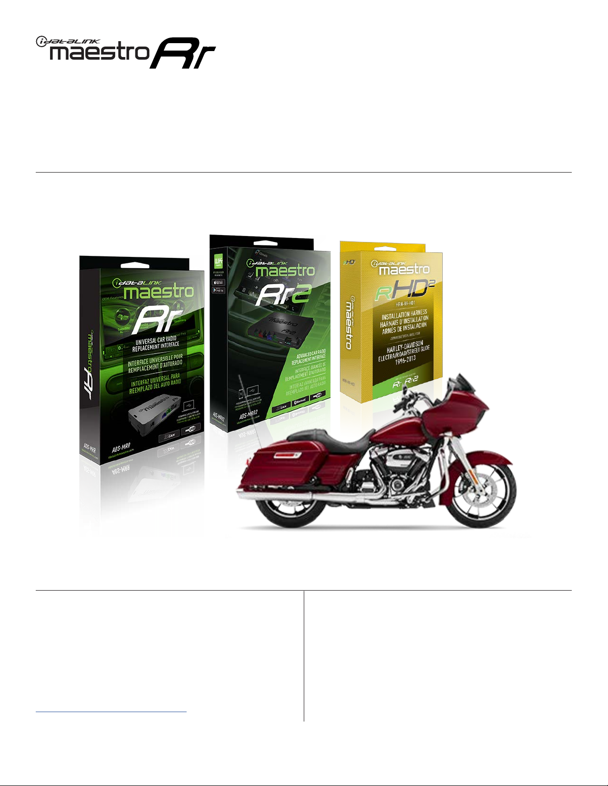
HARLEYDAVIDSON ELECTRA GLIDE 20142023
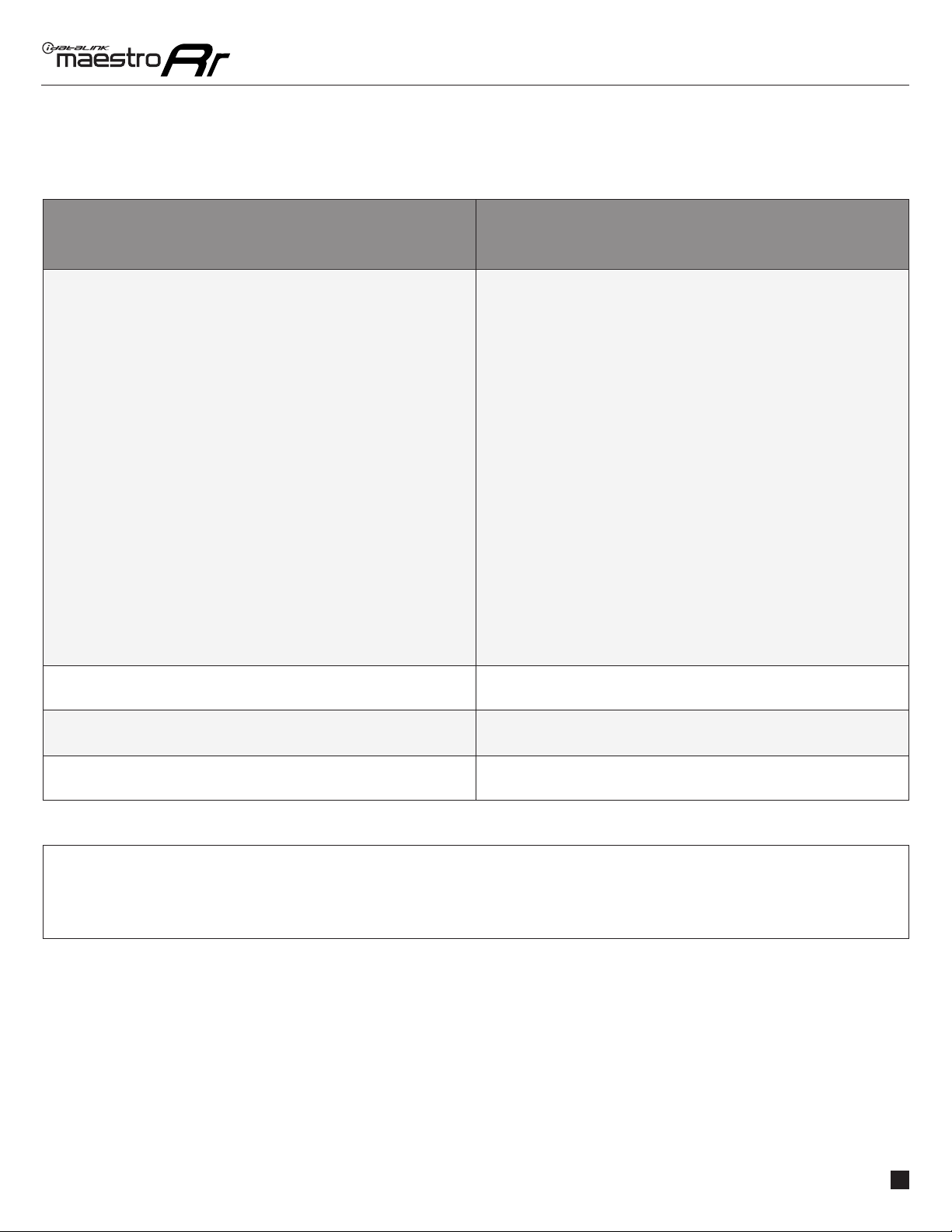
TROUBLESHOOTING TABLE
PROBLEM SOLUTION
Handle bar controls do not work but LED on the Maestro does blink when
steering wheel buttons are pressed.
Ensure the blue 4-pin steering wheel control cable is connected between the
Maestro and the radio. The radio will use either the 3.5mm jack OR the blue/
yellow wire, not both.
Connect the 3.5mm jack from the Maestro blue 4-pin cable to the radio’s
3.5mm port (labeled steering, remote, or wheel). If no such port exists, wire
the blue/yellow to blue/yellow (Kenwood/JVC) or to the radio’s Key 1 wire
(brands not listed/other) and secure the 3.5mm jack. It will not be used.
Verify the buttons are set up in the flash. If any button is set to “none” for
“press once”, it will do nothing. “Hold” column can be left as none and the
“press once” function will operate with one press and when holding the
button.
Refer to radio’s owner’s manual to verify if the radio has this function:
• JVC/Kenwood : Steering Wheel Control (ON/OFF): choose ON
• Nakamichi : if model is listed, ensure PAC mode is on. If “other”, learn the
buttons in the radio steering wheel menu.
• Sony : Steering Wheel Control (Custom/Preset): choose Preset. If phone
buttons do not operate properly, flash the module as Pioneer – 2009 and
newer with BT. Then select “custom” instead of “preset” and learn the
buttons in the radio menu.
• Other brands – radio should have a steering wheel menu to learn the
buttons. You may have to select type A/B/C/1/2/3 and try learning again
if buttons are not saving. Refer to radio manufacturer’s tech support for
further advice if not learning properly.
Sound is very quiet. Cut and remove the RCA connectors and connect the wires to the speaker
outputs of the radio.
Radio does not turn on. Test red and yellow wires for DC voltage at radio using a multimeter. Contact
support if no voltage on red or yellow.
The light on the Maestro is flashing RED ONCE. There is no firmware on the module; flash the RR module.
MAESTRO RR RESET PROCEDURE:
Turn the key to the OFF position, then disconnect all connectors from the module.
Press and hold the module’s programming button and connect all the connectors back to the module. Wait, the module’s LED will flash RED rapidly (this may
take up to 10 seconds).
Release the programming button. Wait, the LED will turn solid GREEN for 2 seconds to show the reset was successful.
TECHNICAL ASSISTANCE
Phone: 1-866-427-2999
IMPORTANT: To ensure proper operation, the aftermarket radio needs to have the latest firmware from the manufacturer. Please visit the radio
manufacturer’s website and look for any updates pertaining to your radio.


-TL2 User manual")