manuals.online logo
Brands
  1. Home
  2. •
  3. Brands
  4. •
  5. Kohler
  6. •
  7. Bathroom Fixture
  8. •
  9. Kohler URBANITY 25717T-9 User manual

Kohler URBANITY 25717T-9 User manual

1418848-2A-C 1
1418848-2A-C 8
INSTALLATION INSTRUCTIONS
URBANITY+
25717T-9 Recessed Thermostatic Dual Shower Faucet-Multifunction Showerhead
URBANITY+
SERVICE PARTS
**Color code must be specified when ordering.
BEFORE YOU BEGIN
All information is based on the latest product information available at the time of publication. Kohler Co. reserves the right
to make changes in product characteristics, packaging, or availability at any time without notice.
Please leave these instructions for the consumer. They contain important information.
OPERATION INSTRUCTIONS
1. Minimum supply pressures: 0.1MPa(1bar).
2. Recommended supply static pressures: 0.3MPa(3bar) on hot and cold water.
3. Supply pressure greater than 0.5MPa(5bar): install a pressure reducer.
4. Hot water temperatures, minimum: 50ºC, maximum: 80ºC.
5. Recommended hot water temperature: 65ºC(energy-saving).
6. Setting range, approximately: 20ºC to 49ºC.
7. Safety stop at: 37ºC.
8. Maximum mixed water temperature: 49ºC.
9. The highest environment temperature for handshower & showerhead is 60ºC. Please keep handshower, showerhead
and shower arm away from heater, or it may become damaged and cause injury to the user.
OPERATION CONDITION
25717T-9 Recessed Thermostatic Dual Shower Faucet-Multifunction Showerhead
The temperature is set by slowly turning the temperature handle(right-hand handle). For safety reasons, there is a stop
that limits temperature to 37ºC. To get a higher temperature, push the button(on right-handle) and continue turning the
temperature handle counter-clockwise.
Water flow and dispense is set by switch buttons. Press any switch button on the faucet body, the water will run from
corresponding outlet. Rotate the switch buttons counter-clockwise to reduce flow.
TOOLS AND MATERIALS (USER SUPPLIED)
Adjustable Wrench Level Drill Pencil Screwdrivers Sealant Tape
Laminar Katalyst rain
Icon description above switch button
Handshower
1069458
77420
1410662-CP
(For CY finish)
1348571**
(For other finishes)
1337970**
1081607
1337971**
1061576
1258634**
23096
833438
833730
3008304
1299843**
3008523
870721
834404
1244920
1347562
864922**
1299837
1299846
1176766
1242353
1299857
1242354
834638
1299821
55925
1377201
1423819**
870992
831752
1299825
1259076
3019692
871472
1248781**
42045
1326364
1249005
833730
1242635
1359717
1306343
1306349
833438
833438
1306348**
1092497
1424140-CP
(For CY finish)
1359706**
(For other finishes)
G1/2˝
G1/2˝
233
335
126
98 514
31~40
76
78
232
50
84
35
68
41.5
302
240
150
Ø42
40
Ø37
29~38
46
149
51×51
49
60
53
1418848-2A-C 7
1418848-2A-C 2
ROUGH-IN DIMENSIONS
The Finished Floor
Recommended Height
1100~1200
Recommended Height
2100~2200
Showerhead
Stop pin
Notch
2. Remove the screw(52) and adapter spline(53), and
then unscrew the nut(55) and stopper(54). Remove
the cartridge cautiously. Clean the thermostatic
cartridge by soaking it in warm vinegar.
2
Cartridge
3
Notch
Stop pin
5
Groove
Round mark
6
①
②
27
50
51
52
53 49
52
53
54
55
1
②
Number 37
①
27
50
51
49
3. After cleaning, install the “stop assembly” back on
the cartridge, adjust the stop pin into the notch.
4. Install the assembly cartridge and stop in the body,
adjust the stop pin into the notch.
5. NOTE: Do not turn the cartridge when reinstalling it.
If you turned it accidentally, you should adjust it and be
sure that the round mark is correctly in line with the
groove, or readjust as per the steps of verification and
setting.
6. Install the adapter spline(without turning the spindle).
Ensure the indicator line on the adapter spline align with
the indicator line on the stopper. Tighten the screw(52)
with a screwdriver. Install the temperature handle(49).
Ensure the number 37 on temperature handle is upward
vertically(After assembly, it could not be turned counter-
clockwise if not pushing the button). Tighten the screw
(50) with 2.5mm hex wrench(27). Insert the plug(51).
Clear the Thermostatic Cartridge
Very hard water can obstruct the filters on the thermostatic cartridge and reduce the water flow. Please clean the cartridge
as follows: Shut off the water supply of the faucet and turn on the water flow valve, then proceed to remove the cartridge.
The cartridge is sensitive part, please be careful.
1. Before your action, make sure the number 37 on the
temperature handle is upward vertically(It could not be
turned counter-clockwise if not pushing the button).
Remove the temperature handle(49).
Indicator line
Upward
horizontally
4
CLEANING INSTRUCTIONS
All Finishes: Clean the finish with mild soap and warm water. Wipe entire surface completely dry with clean soft cloth.
Many cleaners may contain chemicals, such as ammonia, chlorine, toilet cleaner etc. which could adversely affect the
finish and are not recommended for cleaning.
Do not use abrasive cleaners or solvents on Kohler faucets and fittings.
Clear the Filter
The filters can protect the faucet, but it may get obstructed and
reduce water flow after a long time of use. If this happens, , turn
off the water supply.
Take out the plugs(26). Unscrew two screws(25) with 3mm hex
wrench(24) to uninstall faucet. Take out the filters by hand. Clean
the filters by soaking them in warm vinegar. Reinstall in turn.
24
25
26
Filter
1
26
82
Ø8
9
8
5
11 12 10
11 12
10
3
Level
Level
8
8
4

2
2
5
4
2
1 (Not provided)
3
6
7
6
5
3
1
Kloud burst
1
Katalyst rain
1418848-2A-C 3
1418848-2A-C 6
Install the Bracket
Determine a suitable location on the finished wall to install bracket.
Ensure it should avoid buried cables and pipes in the wall.
Mark the mounting holes of the base(42) on the wall according to
the dimension. Drill two holes in the finished wall, the holes should
match the anchors(43) and be vertical. Install the anchors. Tighten
the screws(44) to fix the base on the finished wall. NOTE: The
direction of the base is shown in the figure.
Loosen the screw(47) in the bracket(46) bottom with hex wrench
(45) until the bracket can be installed into the base. Slide the
escutcheon(48) onto the bracket. Apply a ring of plumbers putty or
other sealants around the underside of the escutcheon. Move the
bracket onto the base until it is against the finished wall and
confirm the drain notch and screw hole are pointed down. Tighten
the screw(47) with hex wrench to fix the bracket and escutcheon
on the finished wall. Remove any excess putty or sealant.
Ensure that all connections are tight, the switch buttons are not
turned on. Turn on the water supply. Run water through the valve.
Check for leakage. Repair as needed.
Press the buttons separately. Check whether all connections and
water flow are well. Shut off the faucet.
Verification and Setting
Make sure that the water feeds of the faucet have reach the
highest temperature by running the water sufficiently. When the
number 37 on the temperature handle(49) is upward vertically,
the temperature of the water should be within a range of 36ºC and
38ºC, as measured by a thermometer. If not, the installer can
adjust the setting. Proceed with the setting as follows:
Remove the plug(51). Take out the screw(50) with 2.5mm hex
wrench(27) to uninstall the temperature handle. Remove the
screw(52) with a screwdriver. Remove the adapter spline(53).
Under the normal condition of water flow, slowly turn the
temperature selector(Always in the same direction) from the cold
water position until water temperature reaches 37ºC. If the
temperature goes over 37ºC, go back to the “cold” setting and
reset it. When the temperature is stable, do not turn the cartridge
spindle. Install the adapter spline. Ensure the indicator line on the
adapter spline align with the indicator line on the stopper. Tighten
the screw(52) with a screwdriver. Install the temperature handle.
Ensure the number 37 on the temperature handle is upward
vertically(After assembly, it could not be turned counter-clockwise
if not pushing the button). Tighten the screw(50) with 2.5mm hex
wrench. Insert the plug(51).
42
43
44
45
47
48
46
Drain notch
INSTALLATION CHECKOUT
27
49
50
51
52
53
Number 37
Upward
horizontally
Spindle
Indicator line
CARE AND MAINTENANCE
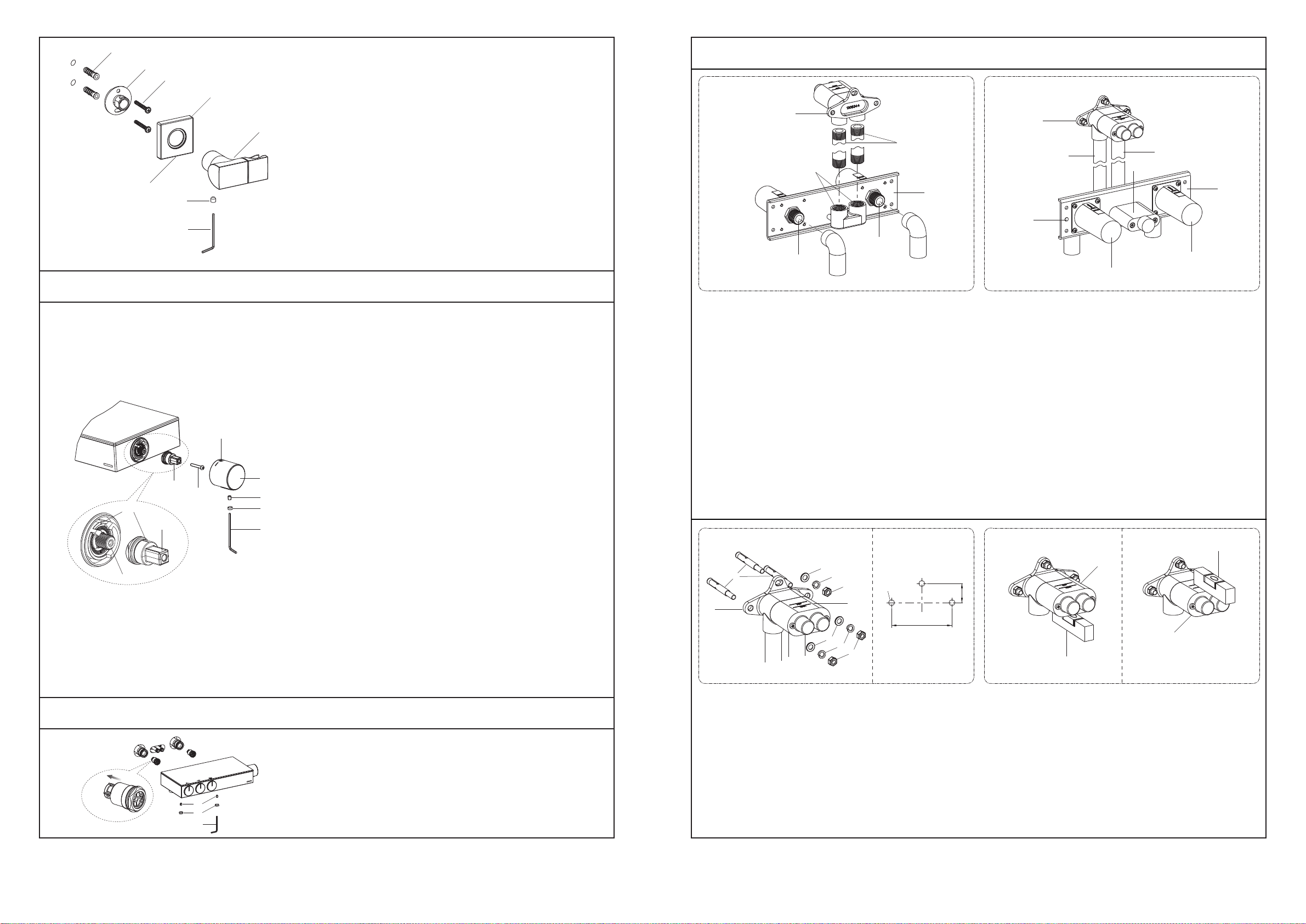
Connect the Pipes
As figure 1shown, apply enough tape or suitable sealant on threads of the showerhead outlet tubes(1, not provided) and
two connections(2). Install the
G1/2˝
hot and cold supply pipes into two connections, and make sure the hot supply should
be installed to the side with red dot of the inlet assembly(3). Connect one end of the showerhead outlet tubes with the
connector(4), and connect the other end with shower arm base(5).
As figure 2shown, ensure the showerhead outlet tubes(1) are connected correctly with shower arm base(5).
Install the Inlet Assembly
During installation, please do not remove the protectors(6, 7) until instructed to do.
Select a location in the vertical wall to install the inlet assembly(3) according to rough-in dimensions. As figure 2shown,
make sure the protectors(6, 7) face front and the inlet assembly with red dot is on the left side. NOTE: Make sure the
centerline of the inlet assembly is vertical to the wall, the upper surfaces of the protectors is horizontal.
INSTALLATION
Hot
Cold
Hot
Cold
Red dot
Install the Shower Arm Base
During installation, please do not remove the protector(8) until instructed to do.
Select a location in the vertical wall to install the base(5) according to rough-in dimensions. Make a suitable hole in the wall.
As figure 3shown, drill three holes(Ø8) as expansion screws’(9) diameter and base position in the wall. The center line
of two horizontal holes should be horizontal. Install the expansion screws. Secure the base, washers(11) and locking
gaskets(12) on the wall with the nuts(10).
As figure 4shown, ensure the bottom of the protector(8) is horizontal by level.
Install the Showerhead
Before installation, install the restrictors if needed. Install the
restrictors into the connectors on the showerhead(33).
Remove the protector caps from the shower arm outlet(34) and
showerhead. Insert the showerhead to the shower arm outlet
as shown.
Insert the pin(35) into the slot. Tighten the screw(36) with 2.5mm
hex wrench(27).
WARNING: Ensure the screw is tightened to avoid the product
falling and personal injury.
10
8 9
25
26
24
2323
21
21
29
29
27
28
27
30
31
31
32
28
30
11 12
91º
17
18
8
Slot
Protector cap
Restrictor
33
35
27 36
34
13 14
21
21 14
7
22
14
Protector cap
37
39
41
40
38
17
18
8
19
20
The finished wall
8
6
14
7
13
(Not provided)
14
15
16
6
765
18
Hot
Cold
1418848-2A-C 5
1418848-2A-C 4
Install the Faucet Body
Cut off the protectors(6) beyond the wall after the wall is finished. As figure 8shown, uninstall and discard the plugs(14)
from the connections(21) with 8mm hex wrench(13, not provided). Remove the screws(22) from the protector(7) with
screwdriver(not provided) and pull it out. Check whether the O-rings on the connections(21) and showerhead tubes(23)
are intact.
As figure 9shown, adjust two screws(25) with 3mm hex wrench(24). Install the faucet body to the connections(21) and
showerhead tubes(23) until it is against the finished wall. Tighten two screws(25) with 3mm hex wrench. Press the
plugs(26) into the faucet.
Water Pressure Test
As figure 5shown, uninstall the protectors(6) with screwdriver(not provided). Remove the plugs(14) with 8mm hex wrench
(13, not provided). Flush water supply pipes for about one minute to remove any debris. Reinstall the plugs. Remove the
protector cap(15) from the protector(7), and connect the connection(16) with one waterpipe(not provided).
As figure 6shown, remove the screws(17) from the protector(8) with screwdriver(not provided) and pull it out. Remove the
connectors(18) with 8mm hex wrench, take off the filter washers(19). Flush water supply pipes for about one minute to
remove any debris. Insert two
G1/2˝
plugs(not provided) into the connections(20).
Apply water pressure(8bar) test on the product. Check for leaks. Turn off the water supplies.
Remove two
G1/2˝
plugs from the connections(20). Reinstall the filter washers(19) and connectors(18). Remove the
waterpipe from the connection(16). Reinstall the protector cap(15) and protectors(6, 8).
As figure 7shown, ensure the out surface of the finished wall is between the MAX and MIN marks on the protectors(6, 8).
Install the Shower Arm
As figure 10 shown, when the finished wall is completed, remove the screws(17) from the protector(8) with screwdriver
(not provided) and pull it out. The angle between connectors(18) and finished wall should be 91 degrees.
As figure 11 shown, loosen the screws(28, 29) with 2.5mm hex wrench(27). Slide the escutcheon(30) onto the shower
arm(31). Install the shower arm with escutcheon onto the connectors(18), tighten the screws(29) with 2.5mm hex wrench
to secure the shower arm. Remain the protector cap(32) on the shower arm before the showerhead is installed.
As figure 12 shown, apply a ring of plumbers putty around the back surface of the escutcheon(30). Push the escutcheon
until it is against the wall. Tighten the screw(28) into the bottom of the escutcheon with 2.5mm hex wrench. Remove any
excess putty.
Install the Handshower
Remove the protector cap from the connector(37).
Put the screen washer(38) into the shower hose(39).
Connect the handshower(40) and connector(37)
with shower hose. Tighten all the connectors.
NOTE: Don’t over tighten.
Install the check valve(41) into the handshower if
needed.
13
(Not provided)
The finished wall

This manual suits for next models

1

Other Kohler Bathroom Fixture manuals

Kohler K-706152 Assembly instructions

Kohler

Kohler K-706152 Assembly instructions

Kohler 2738T User manual

Kohler

Kohler 2738T User manual

Kohler Kumin 97878 Operating manual

Kohler

Kohler Kumin 97878 Operating manual

Kohler K-8013 Assembly instructions

Kohler

Kohler K-8013 Assembly instructions

Kohler K-T12007 Assembly instructions

Kohler

Kohler K-T12007 Assembly instructions

Kohler K-16281 User manual

Kohler

Kohler K-16281 User manual

Kohler K-819 User manual

Kohler

Kohler K-819 User manual

Kohler STERLING 6500 Series User manual

Kohler

Kohler STERLING 6500 Series User manual

Kohler K-15894 User manual

Kohler

Kohler K-15894 User manual

Kohler K-113 User manual

Kohler

Kohler K-113 User manual

Kohler K-852-H2 Assembly instructions

Kohler

Kohler K-852-H2 Assembly instructions

Kohler ARCHER 6220X-4 User manual

Kohler

Kohler ARCHER 6220X-4 User manual

Kohler K-2392 Assembly instructions

Kohler

Kohler K-2392 Assembly instructions

Kohler SKYLINE K-705876T-FM-SHP User manual

Kohler

Kohler SKYLINE K-705876T-FM-SHP User manual

Kohler AWAKEN Geometric 72415T-E User manual

Kohler

Kohler AWAKEN Geometric 72415T-E User manual

Kohler K-T194 User manual

Kohler

Kohler K-T194 User manual

Kohler K-8501 User manual

Kohler

Kohler K-8501 User manual

Kohler STERLING 5400 Series Assembly instructions

Kohler

Kohler STERLING 5400 Series Assembly instructions

Kohler K-11830 Assembly instructions

Kohler

Kohler K-11830 Assembly instructions

Kohler K-9674 User manual

Kohler

Kohler K-9674 User manual

Kohler K-1110 User manual

Kohler

Kohler K-1110 User manual

Kohler K-300 Assembly instructions

Kohler

Kohler K-300 Assembly instructions

Kohler NEW PURIST K-701574T User manual

Kohler

Kohler NEW PURIST K-701574T User manual

Kohler PRESQU ILE K-8745T-U User manual

Kohler

Kohler PRESQU ILE K-8745T-U User manual

Popular Bathroom Fixture manuals by other brands

FM Mattsson 9000E Tronic instructions

FM Mattsson

FM Mattsson 9000E Tronic instructions

KWC EXOS675X Installation and operating instructions

KWC

KWC EXOS675X Installation and operating instructions

Gessi VENTI2O 65101 manual

Gessi

Gessi VENTI2O 65101 manual

eisl DX12004PLUS installation instructions

eisl

eisl DX12004PLUS installation instructions

clage END 1100-04410 Operating and installation instructions

clage

clage END 1100-04410 Operating and installation instructions

Hans Grohe MySelect S Vario 26637400 Assembly instructions

Hans Grohe

Hans Grohe MySelect S Vario 26637400 Assembly instructions

Add-A-Bathroom FP800T installation guide

Add-A-Bathroom

Add-A-Bathroom FP800T installation guide

Grohe Rainshower 28 778 manual

Grohe

Grohe Rainshower 28 778 manual

for Living 063-5799-0 Assembly instructions

for Living

for Living 063-5799-0 Assembly instructions

Hans Grohe Focus 190 31608 Series Instructions for use/assembly instructions

Hans Grohe

Hans Grohe Focus 190 31608 Series Instructions for use/assembly instructions

Hans Grohe ShowerSelect 13596 Series Assembly instructions

Hans Grohe

Hans Grohe ShowerSelect 13596 Series Assembly instructions

Gessi iPsa 33095 Bath Mixing Program

Gessi

Gessi iPsa 33095 Bath Mixing Program

Hagleitner integral 4PLUS manual

Hagleitner

Hagleitner integral 4PLUS manual

Fleurco Evolution 56307 manual

Fleurco

Fleurco Evolution 56307 manual

KWC VITA PRO 2.0 A125 12.528.041.000FL Installation and service manual

KWC

KWC VITA PRO 2.0 A125 12.528.041.000FL Installation and service manual

Dreamline PRISM PLUS installation instructions

Dreamline

Dreamline PRISM PLUS installation instructions

Kinedo 361-A PRE-INSTALLATION

Kinedo

Kinedo 361-A PRE-INSTALLATION

Triton Aria 2181557B quick start guide

Triton

Triton Aria 2181557B quick start guide

manuals.online logo
manuals.online logoBrands
  • About & Mission
  • Contact us
  • Privacy Policy
  • Terms and Conditions

Copyright 2025 Manuals.Online. All Rights Reserved.