EVSE (Electrical Vehicle Supply Equipment)
Pedestal Kit
Cat No. EVPED
For use with Cat Nos. EVR30 and EVR40
INSTALLATION INSTRUCTIONS ENGLISH
DI-000-EVPED-00B
PEDESTAL INSTALLATION
PREPARATION
WARNINGS AND CAUTIONS:
• TO AVOID FIRE, SHOCK, OR DEATH; TURN OFF POWER AT CIRCUIT BREAKER OR FUSE AND TEST THAT POWER IS OFF
BEFORE WIRING!
• READ THE INSTRUCTIONS COMPLETELY. FAILURE TO FOLLOW INSTALLATION INSTRUCTIONS MAY RESULT IN PROPERTY
DAMAGE, INJURY OR DEATH.
• IF YOU HAVE QUESTIONS ABOUT THE INSTALLATION, CONTACT YOUR SERVICE REPRESENTATIVE. DO NOT ATTEMPT TO
PERFORM A PROCEDURE YOU ARE UNSURE OF.
• THE EVSE PEDESTAL MUST BE WIRED PER THE NATIONAL ELECTRICAL CODE®(NEC) AND LOCAL CODES.
• THE EVSE CHARGING STATION AND ELECTRICAL WIRING SHOULD BE INSTALLED BY AN ELECTRICIAN IN ACCORDANCE WITH
LOCAL ELECTRICAL CODES AND REGULATIONS.
FOR CANADA ONLY
For warranty information and/or product returns, residents of Canada should contact Leviton in writing at Leviton Manufacturing of Canada Ltd to the attention of the Quality
Assurance Department, 165 Hymus Blvd, Pointe-Claire (Quebec), Canada H9R 1E9 or by telephone at 1 800 405-5320.
PATENT
This product is covered by U.S. Pat. No. 9,073,446.
For Technical Assistance Call: 1-800-824-3005 (U.S.A. Only) 1 800 405-5320 (Canada Only) www.leviton.com © 2017 Leviton Mfg. Co., Inc.
LIMITED 1 YEAR WARRANTY AND EXCLUSIONS
Leviton warrants to the original consumer purchaser and not for the benefit of anyone else that this product at the time of its sale by Leviton is free of defects in materials and workmanship under normal and proper use for one year from the purchase date. Leviton’s only obligation is to correct such defects by repair or replacement, at its option. For details visit www.leviton.com or call 1-800-824-3005. This warranty excludes and there is disclaimed liability for labor for removal of this
product or reinstallation. This warranty is void if this product is installed improperly or in an improper environment, overloaded, misused, opened, abused, or altered in any manner, or is not used under normal operating conditions or not in accordance with any labels or instructions. There are no other or implied warranties of any kind, including merchantability and fitness for a particular purpose, but if any implied warranty is required by the applicable jurisdiction, the duration
of any such implied warranty, including merchantability and fitness for a particular purpose, is limited to one year. Leviton is not liable for incidental, indirect, special, or consequential damages, including without limitation, damage to, or loss of use of, any equipment, lost sales or profits or delay or failure to perform this warranty obligation. The remedies provided herein are the exclusive remedies under this warranty, whether based on contract, tort or otherwise.
INTRODUCTION
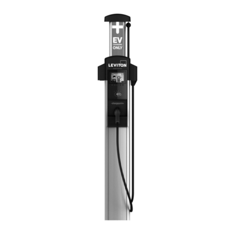
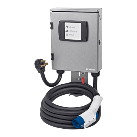
This document provides step-by-step instructions related to the installation of an EVSE Pedestal Kit for the EVR30 and EVR40 Electric Vehicle Charging Stations.
Package Includes:
• (1) 4 in. x 4 in. x 43.5 in. pedestal with cap and two docking bracket assemblies
• (1) Hardware kit - includes (4) #10/32 spanner screws and (4) external tooth-lock washers
• (1) Installation instructions
CONCRETE PAD
NOTE: The requirements below are the manufacturers minimum recommendations only. The location, dimensions and composition of the concrete pad for
supporting the pedestal should always adhere to local building codes.
• The pad must be a minimum of 18 in. square.
• The pad must be a minimum of 24 in. deep.
• Stub-up must be a minimum of 3 in. above the concrete pad.
• Anchor bolts must be a minimum of 2.25 in. above the concrete pad.
• If there is not a wheel stop, the center of the pedestal must be placed at least 36 in. behind the curb.
• If there is a wheel stop, the center of the pedestal must be placed 12 in. behind the curb.
LEVELING
Hex nuts and washers can be placed on the anchor bolts below the pedestal to adjust the vertical alignment of the pedestal should the concrete pad not be level.
When leveling nuts are used, a gap will be present between the concrete pad and pedestal base. This gap should be filled with silicone sealant. Apply silicone per
manufacturers recommendations.
GROUNDING
WARNING: THE EVSE CHARGING STATION IS TO BE CONNECTED TO A GROUNDED, METAL, PERMANENT WIRING SYSTEM. THE EVSE PEDESTAL IS
TO BE CONNECTED TO A SEPARATE GROUND CONDUCTOR RUN AND CONNECTED TO THE GROUNDING LUG AT THE PEDESTAL MOUNTING POLE.
PEDESTAL GROUND
PATH 1: The dedicated pedestal ground can be supplied by a grounding bushing at the end of the stub-up if the conduit is metal and runs back to the service
equipment.
PATH 2: If the conduit is non-conductive or does not run back to the service equipment, use of a grounding rod buried underneath the concrete pad will be required.
EVSE GROUND
The ground wire(s) connected to the EVSE charging station(s) mounted to the pedestal must be fed from the supply equipment.
WARNINGS AND CAUTIONS:
• THE EVSE CHARGING STATION IS TO BE CONNECTED TO A GROUNDED, METAL, PERMANENT WIRING SYSTEM. THE EVSE
PEDESTAL IS TO BE CONNECTED TO A SEPARATE GROUND CONDUCTOR RUN AND CONNECTED TO THE GROUNDING LUG AT
THE PEDESTAL MOUNTING POLE.
• TO ENSURE THAT THE EVSE CHARGING STATION AND PEDESTAL ARE INSTALLED PER AMERICANS WITH DISABILITIES ACT (ADA)
STANDARDS FOR ACCESSIBLE DESIGN GUIDELINES, REFER TO CODE OF FEDERAL REGULATIONS DOCUMENT 28 CFR
PART 36. SECTIONS 4.2 AND 4.4.
• INSTALLER: ENSURE THESE INSTRUCTIONS ARE LEFT WITH THE USER.
• USER: ENSURE THESE INSTRUCTIONS ARE KEPT FOR FUTURE REFERENCE.
WARNING: TO AVOID FIRE, SHOCK, OR DEATH; TURN OFF POWER AT CIRCUIT BREAKER OR FUSE AND TEST THAT POWER IS OFF BEFORE WIRING!
WARNING: READ THE INSTRUCTIONS COMPLETELY. FAILURE TO FOLLOW INSTALLATION INSTRUCTIONS MAY RESULT IN PROPERTY DAMAGE,
INJURY OR DEATH.
1. Trench and run conduit and wiring per local codes and standards. If a ground rod is required in accordance with local and current NEC electrical codes,
see GROUNDING section.
2. Install/Pour concrete pad. NOTE: Refer to the CONCRETE PAD section for pad requirements and Figure 1.
3. Immediately after pouring the concrete, use the anchor bolt template provided to place four type L or J anchor bolts in a 6 in. by 6 in. pattern until concrete
is fully set. Anchor bolts should protrude a minimum of 2.25 in. above the concrete pad. NOTE: Safety bollards may be required; consult your (AHJ) Authority
Having Jurisdiction for details. NOTE: If mounting directly to poured concrete sidewalk, size concrete expansion anchors appropriately based on sidewalk
thickness.
4. Pull conductors from the service equipment to the EVSE pedestal location leaving 5 ft. of wire exposed after the stub-up. The conductors must be long enough
to feed through the EVSE pedestal and flexible conduit with 10 in. of wire remaining to wire the charging station. NOTE: Run dedicated circuits (1 for each
EVSE charging station) as per the EVSE Charging Station Installation Instructions, NEC and local building codes.
5. Remove both outlet box covers and pull the supply conductors and ground wire for the EVSE charging station through the 1-gang opening of the EVSE
pedestal (Figure 2).
6. Position the EVSE pedestal assembly on the anchor bolts. NOTE: Hex nuts and washers can be placed on the anchor bolts below the EVSE pedestal to adjust
the vertical alignment of the EVSE pedestal should the concrete pad not be level. If leveling nuts are used, see LEVELING section and Figure 3.
7. Secure the EVSE pedestal using appropriately sized hex nuts and washers (Figure 3). Apply Anti-Seize compound (recommended for use on all bolts and
nuts) and finish with acorn nuts.
8. Connect the dedicated EVSE pedestal ground wire from the ground bushing (Path 1) or ground rod (Path 2) to the ground lug inside the EVSE pedestal
(Figure 4). This will require a flathead screwdriver entering the 1-gang opening opposite the ground lug. NOTE: Refer to the GROUNDING section and
Figure 4 to ensure both EVSE pedestal and EVSE charging station are properly grounded.
9. Cut out a 3/4 in. hole in one of the outlet box covers to accept a 90 degree liquid tight conduit fitting. Connect the fitting to the outlet box cover and secure
with a locknut (Figure 5).
10. Attach the 3/4 in. flexible liquid tight conduit (approx. 8-1/4 in.) to the conduit fitting.
11. Using a 3/4 to 1 in. reducing bushing, connect a 1 in. hub to the other end of the flexible conduit.
12. Pull supply conductors and ground wire for the EVSE charging station through the outlet box cover, flexible conduit assembly and hub; then secure both outlet
box covers back onto the EVSE pedestal (Figure 5).
13. Mount the EVSE charging station using (2) #10/32 spanner screws and toothlock washers (Figure 6).
14. Connect the flexible conduit assembly and hub to the EVSE charging station.
15. Wire the EVSE charging station (refer to the EVSE Charging Station Installation Instructions).
Additional equipment required (not included) for EVSE charging station installation:
NOTE: Double quantities below when installing two EVSE charging stations.
• (1) Leviton EVR30 and EVR40 EVSE charging stations
• (1) Circuit breaker appropriately sized for the EVSE charging station (refer to EVSE Charging Station Installation Instructions)
• (1) 1 in. hub
• (1) 1 in. to 3/4 in. reducing bushing
• (1) 3/4 in. flexible liquid tight conduit (approx. 8-1/4 in.)
• (1) 3/4 in. 90 degree flexible liquid tight conduit fitting
• (1) Anti-Seize compound (recommended for use on all bolts and nuts)
• (1) Tube of silicone sealant
Required cabling (not included) for EVSE charging station installation:
NOTE: The EVSE pedestal must be wired per NEC and local codes.
NOTE: Double quantities below when installing two EVSE charging stations.
• (2) Line conductors: Appropriately sized for the EVSE charging station current capacity and in accordance with local and current NEC electrical codes
• (1) Ground conductor: Appropriately sized for the EVSE charging station current capacity and in accordance with local and current NEC electrical codes
PREPARATION
Tools Required:
• Level
• Wire cutter
• Wire stripper
• 3/4 in. knockout cutter
• Flexible liquid tight conduit cutter
• #10 spanner driver
• Flat blade screwdriver
• Wrenches appropriately sized for anchor bolts, hex nuts,
conduit fitting and hub
Additional Equipment Required (Not Included) for Pedestal Installation:
• (4) 3/8 in. stainless steel L or J type anchor bolts
(minimum overall length 7 in., minimum thread length 2.25 in.)
• (8) 3/8 in. stainless steel hex nuts and washers
• (4) 3/8 in. stainless steel acorn nuts

