Nibe SAM 41 User guide

Installer manual
LEK
SAM 41
Supply air module
IHB GB 1635-2
331778


Table of Contents
41 Important information
4Safety information
72 Delivery and handling
7Transport
7Assembly
7Supplied components
7Removing the covers
8
3 The design of the supply air mod-
ule
104 Pipe and ventilation connections
10General pipe connections
10Symbol key
10Outline diagram
11Dimensions and pipe connections
11Mounting
12Heating medium side
14General ventilation connection
14Ventilation flow
14Adjusting ventilation
155 Electrical connections
15General
15Connections
166 Commissioning and adjusting
16Preparations
16Connecting to heating medium system
16Start-up and inspection
177 Program settings
17Start guide
17Menu system
188 Disturbances in comfort
18Info menu
18Manage alarm
18Troubleshooting
209 Accessories
2110 Technical data
21Dimensions and setting-out coordinates
22Technical specifications
23Energy labelling
24Electrical circuit diagram
25Index
3Table of Contents |SAM 41

Safety information
This appliance can be used by children
aged from 8 years and above and per-
sons with reduced physical, sensory or
mental capabilities or lack of experience
and knowledge if they have been given
supervision or instruction concerning use
of the appliance in a safe way and under-
stand the hazards involved. Children shall
not play with the appliance. Cleaning
and user maintenance shall not be made
by children without supervision.
Rights to make any design or technical
modifications are reserved.
©NIBE 2016.
Symbols
NOTE
This symbol indicates danger to machine or
person.
Caution
This symbol indicates important information
about what you should observe when maintain-
ing your installation.
TIP
This symbol indicates tips on how to facilitate
using the product.
Marking
SAM 41 is CE marked and fulfils IP21.
The CE marking means that NIBE ensures that the
product meets all regulations that are placed on it based
on relevant EU directives. The CE mark is obligatory for
most products sold in the EU, regardless where they are
made.
IP21 means that objects with a diameter larger than or
equivalent to 12.5 mm cannot penetrate and cause
damage and that the product is protected against vertic-
ally falling drops of water.
Software version
The heat pump must have software version 2653 or later.
Visit www.nibeuplink.com and click on the tab "Soft-
ware" to download the latest software to your installa-
tion or use the enclosed USB memory.
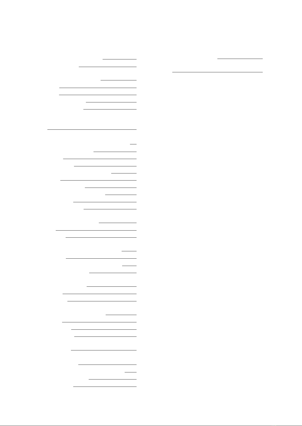
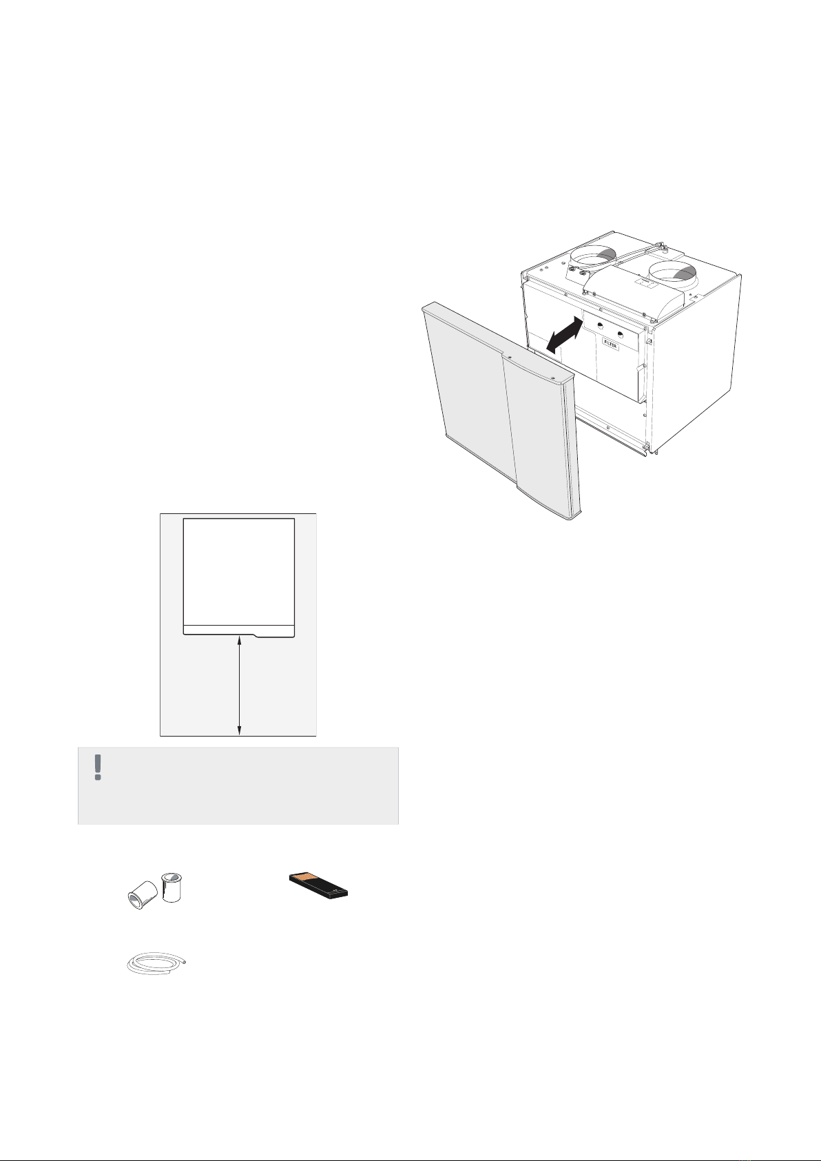
Serial number
The serial number can be found at the bottom left inside
the front cover.
LEK
Serial number
Caution
You need the product's 14 digit serial number
for servicing and support.
Recovery
Leave the disposal of the packaging to the in-
staller who installed the product or to special
waste stations.
When disposing of the product, the constituent
materials and components, such as compressors,
fans, circulation pumps and circuit boards, must be dis-
posed of at a special waste station or at a dealer who
provides this type of service.
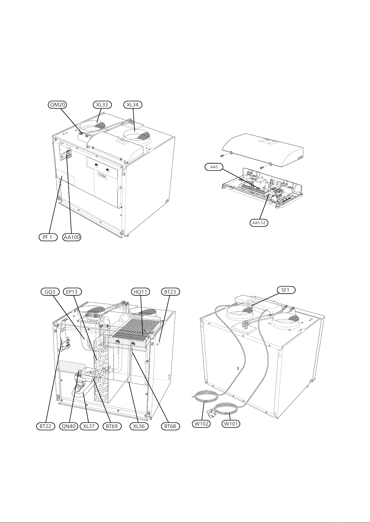
To access the separate components, refer to the section
that shows the construction of the product. No special
tools are required for access.
Improper disposal of the product by the user results in
administrative penalties in accordance with current legis-
lation.
Country specific information
Installer manual
This installer manual must be left with the customer.
SAM 41Chapter 1 | Important information4
1 Important information

Inspection of the installation
In addition, fill in the page for the installation data in the User Manual.
Current regulations require the supply air module to be inspected before it is put into service. The inspection must
be carried out by a suitably qualified person.
DateSignatureNotesDescription
✔
Ventilation (page 14)
Setting ventilation flow exhaust air
Setting ventilation flow supply air
Heating medium (page 12)
System flushed
Accessories bled
Check against output and pressure drop
diagrams
Connected according to outline diagram
Electricity (page 15)
Supply connected 230 V
Connected communication
5Chapter 1 | Important informationSAM 41

Contact information
KNV Energietechnik GmbH, Gahberggasse 11, 4861 SchörflingAT
Tel: +43 (0)7662 8963-0 Fax: +43 (0)7662 8963-44 E-mail: mail@knv.at www.knv.at
NIBE Wärmetechnik c/o ait Schweiz AG, Industriepark, CH-6246 AltishofenCH
Druzstevni zavody Drazice s.r.o, Drazice 69, CZ - 294 71 Benatky nad JizerouCZ
NIBE Systemtechnik GmbH, Am Reiherpfahl 3, 29223 CelleDE
Vølund Varmeteknik A/S, Member of the Nibe Group, Brogårdsvej 7, 6920 VidebækDK
NIBE Energy Systems OY, Juurakkotie 3, 01510 VantaaFI
NIBE Energy Systems France Sarl, Zone industrielle RD 28, Rue du Pou du Ciel, 01600 ReyrieuxFR
NIBE Energy Systems Ltd, 3C Broom Business Park, Bridge Way, Chesterfield S41 9QGGB
NIBE Energietechniek B.V., Postbus 634, NL 4900 AP OosterhoutNL
ABK AS, Brobekkveien 80, 0582 Oslo, Postadresse: Postboks 64 Vollebekk, 0516 OsloNO
NIBE-BIAWAR Sp. z o. o. Aleja Jana Pawła II 57, 15-703 BIAŁYSTOKPL
Tel: 085 662 84 90 Fax: 085 662 84 14 E-mail: sekretariat@biawar.com.pl www.biawar.com.pl
© "EVAN" 17, per. Boynovskiy, Nizhny NovgorodRU
NIBE AB Sweden, Box 14, Hannabadsvägen 5, SE-285 21 MarkarydSE
For countries not mention in this list, please contact Nibe Sweden or check www.nibe.eu for more information.
SAM 41Chapter 1 | Important information6

Transport
The supply air module must be transported and stored
dry.
Assembly
SAM 41 is mounted free-standing on brackets Noise
from the fan can be transferred to the brackets.
■Install the brackets to an outside wall, ideally in a room
where noise does not matter, in order to eliminate
noise problems. If this is not possible, avoid placing it
against a wall behind a bedroom or other room where
noise may be a problem.
■Wherever the unit is located, walls to sound sensitive
rooms should be fitted with sound insulation.
■Route pipes so they are not fixed to an internal wall
that backs on to a bedroom or living room.
Installation area
Leave a free space of 800 mm in front of the supply air
module. All service on SAM 41 can be carried out from
the front.
800
NOTE
Ensure that there is sufficient space (300 mm)
above the supply air module for installing vent-
ilation hoses.
Supplied components
USB memory
1 x
Support bushes
2 x
LEK
Vent hose
1 x
Removing the covers
Front cover
1. Remove the service cover by pulling it straight out.
LEK
7Chapter 2 | Delivery and handlingSAM 41
2 Delivery and handling

LEK
LEK
S3 AA5-S2 AA5
AA5
AA5-S2
LEK
XL34XL33QM20
PF 1 AA100
LEK
SF1
W102 W101
LEK
GQ3 EP13
QN40
BT23
XL36XL37 BT69 BT68BT22
HQ11
SAM 41Chapter 3 | The design of the supply air module8
3 The design of the supply air module

Pipe connections
Ventilation connection supply airXL33
Ventilation connection outdoor airXL34
Connection, heating medium inXL36
Connection, heating medium out 1
XL37
HVAC components
Supply air batteryEP13
Venting heating mediumQM20
Control valve heating mediumQN40
Sensors etc.
Temperature sensor, supply air1
BT22
Temperature sensor, outdoor airBT23
Temperature sensor, flow1
BT68
Temperature sensor, return1
BT69
Electrical components
Accessory cardAA5
Dip switchAA5-S2
Joint cardAA100
Switch, position 0 - 1, main switchSF1
Cord with connection plugW101
Communication cableW102
Ventilation
Supply air fanGQ3
Air filter supply airHQ11
Miscellaneous
Rating platePF1
1Not visible in the image
Designations in component locations according to
standard IEC 81346-1 and 81346-2.
9Chapter 3 | The design of the supply air moduleSAM 41

General pipe connections
Pipe installation must be carried out in accordance with
current norms and directives.
Symbol key
MeaningSymbol
Shut-off valve
Non-return valve
Level vessel
Control valve
Shunt / shuttle valve
Safety valve
Temperature sensor
Expansion vessel
Circulation pump
Fan
Compressor
Heat exchanger
Radiator system
Domestic hot water
Outline diagram
NOTE
External frost protection must be installed in the
outdoor air duct.
-EB100 -AZ2
-CP1
-EB100
-CP1
-AZ2
NOTE
If several climate systems (ECS 40/ECS 41) are
present, SAM 41 must be connected in parallel
with climate system 1. A circulation pump must
be used to ensure the flow over SAM 41.
SAM 41Chapter 4 | Pipe and ventilation connections10
4 Pipe and ventilation connections

Dimensions and pipe
connections
280
25
525
Mounting
Installing on brackets
1. Install SAM 41 on BAU 10 brackets, see images be-
low.
2. Connect heating medium pipes and ventilation
ducts. Use the enclosed support bushes.
LEK
3 - 5 mm
LEK
11Chapter 4 | Pipe and ventilation connectionsSAM 41

Heating medium side
During hot water production and when F750 is defrost-
ing, no energy is transferred to the climate system.
Therefore, for full function of the supply air module, the
stored energy must be available in the climate system
during these operating cases. Energy is stored in the cli-
mate system's water volume. For full function of SAM 41
the waterborne climate system (including the internal
volume in F750) must have a total water volume of at
least 95 litres. If this volume requirement is not met, the
system volume is increased with volume vessel (NIBE
UKV).
Dimensioning the system
1. Work from the water temperature at DUT (DVUT).
2. Work from the current supply air flow.
3. Work from the desired supply air temperature, then
calculate the output that SAM 41 must give at DUT.
4. Determine the water flow across SAM 41 from the
correct output diagram. NOTE! For supply temperat-
ures that are not in one of the diagrams, an estimate
(linear interpolation) can be carried out.
5. Work from the projected pressure drop (at the pro-
jected flow) in the water borne system, climate sys-
tem 1.
6. Check in the pressure drop diagram that the working
point is inside the grey working range.
7. Check that the pump capacity from F750 is sufficient
for both the heating system and SAM 41.
NOTE
If information regarding the present flow is
missing in the diagram there is a risk of frost
damage to the supply air coil.
Output transfer to the supply air
Supply temperature 35°C
175150 200 225 250
70 80 90 100 110 1206050
275 300 325 350 375 400 425 450
1800
2200
2600
3000
3400
3800
4200
4600
5400
5000
Framledningstemperatur 35° C, - 10°C DUT
Tilluftsflöde m3/h
600 l/h
300 l/h
175 l/h
Tilluftsflöde l/h
Effekt (w)
Power (W) Supply temperature 35°C, -10°C DOT
600 l/h
300 l/h
175 l/h
Supply air
flow
(m3/h
(l/s)
175150 200 225 250
70 80 90 100 110 1206050
275 300 325 350 375 400 425 450
2200
2600
3000
3400
3800
4200
5000
5400
5800
6200
6600
4600
Framledningstemperatur 35° C, - 20°C DUT
Tilluftsflöde m3/h
600 l/h
400 l/h
250 l/h
Tilluftsflöde l/h
Effekt (w)
Power (W) Supply temperature 35°C, -20°C DOT
600 l/h
250 l/h
Supply air flow
(m3/h
(l/s)
400 l/h
175150 200 225 250
70 80 90 100 110 1206050
275 300 325 350 375 400 425 450
3000
3400
3800
4200
4600
5400
5800
6200
6600
5000
Framledningstemperatur 35° C, - 30°C DUT
Tilluftsflöde m3/h
600 l/h
450 l/h
350 l/h
Tilluftsflöde l/h
Effekt (w)
7000
7400
7800
Power (W) Supply temperature 35°C, -30°C DOT
600 l/h
450 l/h
350 l/h
Supply air
flow
(m3/h
(l/s)
175150 200 225 250
70 80 90 100 110 1206050
275 300 325 350 375 400 425 450
3400
3800
4200
4600
5000
5800
6200
6600
7000
5400
Framledningstemperatur 35° C, - 38°C DUT
Tilluftsflöde m3/h
600 l/h
400 l/h
Tilluftsflöde l/h
Effekt (w)
7400
7800
8200
8600
9000
Power (W) Supply temperature 35°C, -38°C DOT
600 l/h
400 l/h
Supply air
flow
(m3/h
(l/s)
SAM 41Chapter 4 | Pipe and ventilation connections12

Supply temperature 45°C
175150 200 225 250
70 80 90 100 110 1206050
275 300 325 350 375 400 425 450
2000
2400
2800
3200
3600
4000
4400
4800
5600
6000
6400
6800
5200
Framledningstemperatur 45° C, - 10°C DUT
Tilluftsflöde m3/h
600 l/h
200 l/h
100 l/h
Tilluftsflöde l/h
Effekt (w)
Power (W) Supply temperature 45°C, -10°C DOT
600 l/h
200 l/h
Supply air
flow
(m3/h
(l/s)
100 l/h
175150 200 225 250
70 80 90 100 110 1206050
275 300 325 350 375 400 425 450
2600
3000
3400
3800
4200
4600
5000
5800
6200
6600
7000
7400
7800
5400
Framledningstemperatur 45° C, - 20°C DUT
Tilluftsflöde m3/h
600 l/h
200 l/h
150 l/h
Tilluftsflöde l/h
Effekt (w)
Power (W) Supply temperature 45°C, -20°C DOT
600 l/h
200 l/h
Supply air
flow
(m3/h
(l/s)
150 l/h
175150 200 225 250
70 80 90 100 110 1206050
275 300 325 350 375 400 425 450
3000
3400
3800
4200
4600
5000
5800
6200
6600
7000
7400
5400
Framledningstemperatur 45° C, - 30°C DUT
Tilluftsflöde m3/h
600 l/h
350 l/h
200 l/h
Tilluftsflöde l/h
Effekt (w)
7800
8200
8600
9000
Power (W) Supply temperature 45°C, -30°C DOT
600 l/h
350 l/h
Supply air
flow
(m3/h
(l/s)
200 l/h
175150 200 225 250
70 80 90 100 110 1206050
275 300 325 350 375 400 425 450
3600
4000
4400
4800
5200
6000
6400
6800
7200
5600
Framledningstemperatur 45° C, - 38°C DUT
Tilluftsflöde m3/h
600 l/h
400 l/h
250 l/h
Tilluftsflöde l/h
Effekt (w)
7600
8000
8400
8800
9200
9600
10000
Power (W) Supply temperature 45°C, -38°C DOT
600 l/h
400 l/h
Supply air
flow
(m3/h
(l/s)
250 l/h
Supply temperature 55°C
175150 200 225 250
70 80 90 100 110 1206050
275 300 325 350 375 400 425 450
2000
2400
2800
3200
3600
4000
4400
4800
5600
6000
6400
6800
7200
7600
8000
5200
Framledningstemperatur 55° C, - 10°C DUT
Tilluftsflöde m3/h
600 l/h
200 l/h
75 l/h
Tilluftsflöde l/h
Effekt (w)
Power (W) Supply temperature 55°C, -10°C DOT
600 l/h
200 l/h
Supply air
flow
(m3/h
(l/s)
75 l/h
175150 200 225 250
70 80 90 100 110 1206050
275 300 325 350 375 400 425 450
2800
3200
3600
4000
4400
4800
5200
5600
6400
6800
7200
7600
8000
8400
8800
6000
Framledningstemperatur 55° C, - 20°C DUT
Tilluftsflöde m3/h
600 l/h
200 l/h
125 l/h
Tilluftsflöde l/h
Effekt (w)
9600
9200
Power (W) Supply temperature 55°C, -20°C DOT
600 l/h
200 l/h
Supply air
flow
(m3/h
(l/s)
125 l/h
175150 200 225 250
70 80 90 100 110 1206050
275 300 325 350 375 400 425 450
3400
2600
3000
3400
3800
4200
5000
5400
5800
6200
6600
4600
Framledningstemperatur 55° C, - 30°C DUT
Tilluftsflöde m3/h
600 l/h
300 l/h
150 l/h
Tilluftsflöde l/h
Effekt (w)
6600
6600
6600
6600
6600
6600
6600
Power (W) Supply temperature 55°C, -30°C DOT
600 l/h
300 l/h
Supply air
flow
(m3/h
(l/s)
150 l/h
175150 200 225 250
70 80 90 100 110 1206050
275 300 325 350 375 400 425 450
3800
4200
4600
5000
5400
6200
6600
7000
7400
5800
Framledningstemperatur 55° C, - 38°C DUT
Tilluftsflöde m3/h
600 l/h
300 l/h
175 l/h
Tilluftsflöde l/h
Effekt (w)
7800
8200
8600
9000
9400
9800
10200
10600
11000
11400
Power (W) Supply temperature 55°C, -38°C DOT
600 l/h
300 l/h
Supply air flow
(m3/h
(l/s)
175 l/h
13Chapter 4 | Pipe and ventilation connectionsSAM 41

Working range SAM 41
0
5
10
15
20
25
30
35
0 100 200 300 400 500 600 700 800 900 1000
Tryckfall över SAM 40
(l/h)
Flöde
Tillgängligt tryck (kPa)
Available pressure ( kPa )
Flow
(l/s)
Required system pressure drop
The diagram shows the climate system's required pres-
sure drop. Note that the pressure drop across SAM 41 is
the same as that across the climate system 1.
Check that the working point is inside the grey range. If
the working point is inside the darker grey range to the
left in the diagram, it can give an oscillating supply air
temperature. At too low pressure drop across the climate
system 1, one risks falling within the white area. In this
range, there is a risk of too low water flow through the
supply air module and there is a risk of freezing.
NOTE
Venting may be necessary on installation and
after a period of use. Vent through vent valve
(QM20).
General ventilation connection
Ventilation installation must be carried out in accordance
with current norms and directives.
To prevent fan noise being transferred to the supply air
devices, install a silencer in the duct. This is especially
important if there are supply air inlets in bedrooms.
Connections must be made via flexible hoses, which must
be installed so that they are easy to replace. The air
should be routed to the outdoor air duct through an
outside wall grille in the facade. The outer wall grille
must be installed protected from the weather and must
be designed so that no rain water can penetrate the
facade or follow the air into the duct. The outdoor air
duct must be provided with diffusion-tight insulation
over its entire length. Ensure that the condensation insu-
lation is sealed at any joints and/or at lead-in nipples,
silencers, roof cowls or similar.
Provision must be made for inspection and cleaning of
the duct. Make sure that there are no reductions in cross-
sectional area in the form of creases etc., since this will
reduce the ventilation capacity. The air duct system must
be a minimum of air tightness class B.
When external devices that affect the ventilation are
used, for example kitchen fans and stoves, ensure that
the heat pump is operating. A heat pump that is
switched off does not heat the supply air module and
there is risk of freezing at low outdoor temperatures.
The frost protection must be dimensioned to seal against
the underpressure that can be created in the house when
a fire is lit in the stove when the supply air fan and heat
pump are switched off. An external supply air duct for
the stove is recommended.
Ø160
195
160
450
275
LEK
Supply air
Outdoor air
NOTE
External frost protection must be installed in the
outdoor air duct.
Ventilation flow
The supply air flow must be lower than the exhaust air
flow to prevent over pressure in the house.
Ensure that the ventilation openings are not blocked.
Set the ventilation capacity in the heat pump's menu
system (menu 5.1.6).
Adjusting ventilation
To obtain the necessary air exchange in every room of
the house, the exhaust air device and the supply air
device must be correctly positioned and adjusted and
the fans in the heat pump and supply air module adjus-
ted.
Immediately after installation adjust the ventilation so
that it is set according to the projected value of the
house.
A defective ventilation installation may lead to reduced
installation efficiency and thus poorer operating eco-
nomy, and may result in moisture damage to the house.
SAM 41Chapter 4 | Pipe and ventilation connections14

General
All electrical equipment is connected at the factory.
■Disconnect SAM 41 before insulation testing the house
wiring.
■For the supply air module wiring diagram, see page
24.
■Signal cables to external connections must not be laid
close to high current cables.
■If the supply cable is damaged, only NIBE, its service
representative or similar authorised person may replace
it to prevent any danger and damage.
NOTE
Electrical installation and service must be carried
out under the supervision of a qualified electri-
cian. Electrical installation and wiring must be
carried out in accordance with the stipulations
in force.
Connections
Connecting to F750
This section describes the electrical connection for con-
trolling SAM 41 from NIBE F750.
The heat pump switch must be moved to position " "
and the switch (SF1) on SAM 41 to position 0, before any
work can be started.
1. Ensure that the products are completely disconnec-
ted from the power source. Remove the front hatch
and protective cover to the input card on the heat
pump according to the instructions in its Installer's
manual.
2. Connect cable W102 to position X4 on the input
board (AA3) in the heat pump according to the wir-
ing diagram on page 24. Use the cable lead-in in the
heat pump when routing cables.
If several accessories are to be connected or are
already installed, the adjacent wiring diagram must
be followed.
3. Fix external cable routing.
4. Install the protective cover and the service cover ac-
cording to the heat pump Installation manual.
5. Connect plug W101.
1
2
3
4
5
6
7
8
AA5-X4
15
A
B
GND
A
B
GND
A
B
GND
A
B
GND
A
B
GND
14
13
AA3-X4
1
2
3
4
5
6
7
8
AA5-X4
Accessory card 1
Accessory card 2
ON
12345678
-X9
-X2
24 20212223 1516171819 1011121314 56789 1
1
N
L
PE
PE
1
2
3
4
5
6
7
8
2
3
4
5
6
7
8
9
234
-X8
-X4
-X10
-X1
AA5-X4
ON
12345678
-X9
-X2
24 20212223 1516171819 1011121314 56789 1
1
N
L
PE
PE
1
2
3
4
5
6
7
8
2
3
4
5
6
7
8
9
234
-X8
-X4
-X10
-X1
AA5-X4
EB100
LEK
F750
AA3-X4
DIP switch
The DIP-switch (S2) on the accessory board (AA5) is set
in the factory as below.
ON
12345678
ON
12345678
-X9
-X2
24 20212223 1516171819 1011121314 56789 1
1
N
L
PE
PE
1
2
3
4
5
6
7
8
2
3
4
5
6
7
8
9
234
-X8
-X4
-X10
-X1
AA5-S2
15Chapter 5 | Electrical connectionsSAM 41
5 Electrical connections

Preparations
1. Check that the switch (SF1) for F750 is in position
"
2. Check that the filling valves (QM10) and (QM11) in
the heat pump are fully closed.
Connecting to heating medium
system
1. Connect SAM 41 according to the outline diagram
on page 10.
2. Fill with water using the filler valve (QM11) in F750.
3. Vent the heating medium system with the vent
valves (QM20) above SAM 41, and the vent valves
in F750 and fill if necessary using the filler valve
(QM11) in F750.
Start-up and inspection
Caution
Check the miniature circuit-breaker (FA1) in the
heat pump. It may have tripped during transport-
ation.
Setting the ventilation
Ventilation must be set according to applicable stand-
ards. The supply air flow is adjusted so that it is 80% of
the exhaust air flow. The setting is made in menu 5.1.6.
Even if ventilation is roughly set at installation it is import-
ant that a ventilation adjustment is ordered and permit-
ted.
NOTE
Order a ventilation adjustment to complete the
setting.
Ventilation capacity
0 20 40 60 80 100 120 140 160
0
100
200
300
400
600
500
Tilluftsflöde l/s
Tryck (Pa)
Available pressure (Pa)
Airflow (l/s)
Output
0 20 40 60 80 100 120 140
0
80
200
100
Luftfl de l/s
Effekt (W)
20
40
60
180
120
140
160
Power fan (W)
Airflow (l/s)
Setting of supply air temperature
Set the supply air temperature in menu 5.3.9 (ext sup air
md).
Note that when changing the supply air temperature,
the settings for other parts of the climate system need
to be adjusted.
outdoor temp.T1
supply air temp. at T1
outdoor temp.T2
°C
°C
°C
ext sup air md 5.3.9
supply air temp. at low outd
temp.
supply air temp. at avg outdoor
temp.
SAM 41Chapter 6 | Commissioning and adjusting16
6 Commissioning and adjusting

Caution
See the documentation for the main product.
Start guide
NOTE
There must be water in the climate system be-
fore the switch in F750 is set to " ".
1. Set switch (SF1) onSAM 41 in position "1".
2. Set the heat pump's switch (SF1) to "".
3. Follow the instructions in the start guide in the heat
pump display. If the start guide does not start when
you start the heat pump, start it manually in menu
5.7.
The first time the heat pump is started a start guide is
started. The start guide instructions state what needs to
carried out at the first start together with a run through
of the heat pump’s basic settings.
The start guide ensures that start-up is carried out cor-
rectly and cannot be bypassed.The start guide can be
started later in menu 5.7.
Caution
As long as the start guide is active, no function
in the installation will start automatically.
The guide will appear at each installation restart
until it is deselected on the last page.
Menu system
If you do not make all settings via the start guide or need
to change any of the settings, this can be done in the
menu system.
Menu 5.2 -system settings
Activating/deactivating of accessories.
Select: "ext sup air md"
Caution
This accessory may require a program software
update in your F750.
The heat pump software must be version 2653
or later.
17Chapter 7 | Program settingsSAM 41
7 Program settings

In most cases, the heat pump F750 notes operational
interference (operational interference can lead to dis-
turbance in comfort) and indicates this with alarms and
shows action instructions in the display.
Info menu
All the heat pump measurement values are gathered
under menu 3.1 in the heat pump menu system. Looking
through the values in this menu can often simplify find-
ing the source of the fault. See help menu or user
manual for more information about menu 3.1.
All the heat pump measurement values are gathered
under menu 3.1 in the heat pump menu system. Looking
through the values in this menu can often simplify find-
ing the source of the fault.
Manage alarm
info / action
reset alarm
aid mode
Low pressure alarm
alarm
In the event of an alarm, some kind of malfunction has
occurred, which is indicated by the status lamp changing
from green continuously to red continuously. In addition,
an alarm bell appears in the information window.
Alarm
In the event of an alarm with a red status lamp a malfunc-
tion has occurred that the heat pump cannot remedy
itself. In the display, by turning the control knob and
pressing the OK button, you can see the type of alarm it
is and reset it. You can also choose to set the heat pump
to aid mode.
info / action Here you can read what the alarm means
and receive tips on what you can do to correct the
problem that caused the alarm.
reset alarm In most cases it is enough to select "reset
alarm" to correct the problem that caused the alarm. If
a green light illuminates after selecting "reset alarm" the
alarm has been remedied. If a red light is still visible and
a menu called ”alarm” is visible in the display, the prob-
lem that caused the alarm remains. If the alarm disap-
pears and then returns, see the troubleshooting section
(page 18).
aid mode ”aid mode” is a type of emergency mode. This
means that the heat pump produces heat and/or hot
water despite there being some kind of problem. This
can mean that the heat pump's compressor is not run-
ning. In this case the immersion heater produces heat
and/or hot water.
NOTE
To select aid mode an alarm action must be se-
lected in the menu 5.1.4.
Caution
Selecting "aid mode” is not the same as correct-
ing the problem that caused the alarm. The
status lamp will therefore continue to be red.
Troubleshooting
If the operational interference is not shown in the display
the following tips can be used:
Basic actions
Start by checking the following possible fault sources:
■That the heat pump is running or that the supply cable
to SAM 41 is connected.
■Group and main fuses of the accommodation.
■The property's earth circuit breaker.
■The heat pump's miniature circuit breaker (FA1).
■The heat pump's temperature limiter (FD1).
■Correctly set load monitor (if installed).
Low hot water temperature or a lack of hot
water
■The heat pump has temporarily prioritised supply air
ventilation to prevent too low temperatures in the
supply air coil.
Low room temperature
■Air in the heating medium system.
–Vent SAM 41 using vent valve (QM20).
■Incorrect value set in supply air automatic control sys-
tem.
–Enter menu 5.3.9 (ext sup air md) and adjust the
setting for the supply air temperature.
High room temperature
■Incorrect value set in supply air automatic control sys-
tem.
–Enter menu 5.3.9 (ext sup air md) and adjust the
setting for the supply air temperature.
Low or a lack of ventilation
■Filter (HQ11) blocked.
–Clean or replace the filter.
■The ventilation is not adjusted.
–Order/implement ventilation adjustment.
■Supply air device closed, blocked or throttled down
too much.
–Check and clean the supply air device.
■Check external frost protection.
SAM 41Chapter 8 | Disturbances in comfort18
8 Disturbances in comfort

High or distracting ventilation
■Filter (HQ11) blocked.
–Clean or replace the filter.
■The ventilation is not adjusted.
–Order/implement ventilation adjustment.
Low supply air temperature
■Air in the heating medium system.
–Vent SAM 41 using vent valve (QM20).
■Incorrect value set in supply air automatic control sys-
tem.
–Enter menu 5.3.9 (ext sup air md) and reduce the
setting for the supply air temperature.
High supply air temperature
■Incorrect value set in supply air automatic control sys-
tem.
–Enter menu 5.3.9 (ext sup air md) and adjust the
setting for the supply air temperature.
19Chapter 8 | Disturbances in comfortSAM 41

Bracket BAU 10
For wall mounting of SAM 41
Part no. 067 526
RSK no. 621 23 22
Buffer vessel UKV
UKV 40
Work tank for connection to heat pump system.
Part no. 088 470
Top cabinet
Top cabinet for concealing the ventilation ducts.
385-635 mm
Part no. 067 519
245 mm
Part no. 067 517
345 mm
Part no. 067 518
SAM 41Chapter 9 | Accessories20
9 Accessories
Other manuals for SAM 41
1
Table of contents
Other Nibe Control Unit manuals
Popular Control Unit manuals by other brands

Ferro
Ferro G18 manual

belinus
belinus GlasGlas Module installation instructions

Agilent Technologies
Agilent Technologies E2261A User's manual and programming guide

SMC Networks
SMC Networks SYJA300 Series Operation manual

PEHA
PEHA PHC 940/24 EM Installation and operating instruction

M-system
M-system R7ML-EC8D instruction manual