Ofs 432 User manual

Issue2
November 14, 2011
- 0 -
432 Outdoor Fiber
Distribution Cabinets
Installation Manual

Issue2
November 14, 2011
- 1 -
COPYRIGHT
© 2011, Furukawa Electric North America, Inc.
All Rights Reserved
Printed in the U.S.A
REVISION HISTORY
Issue 1 August 18, 2011 Original Release Date
TRADEMARK INFORMATION
OFS is trademark of Furukawa Electric North America, Inc.
DISCLAIMER OF LIABILITY
The contents of this document as of the date of publication are current. OFS reserves the
right to change the contents without prior notice. OFS in no way will be liable for any
damages resulting from loss of information, use or profits. OFS further disclaims all
liability direct or indirect, consequential or incidental for all product, publications and
services during and after the warranty period.

Issue2
November 14, 2011
- 2 -
TABLE OF CONTENTS
About this Manual 3
Product Overview 3
Product Specifications 5
Warnings 6
Inspecting Shipment 6
Replacement and Accessory Kits 6
Installation 7
Pole Mounting 7
Pad Installation 10
Grounding 14
Fiber Routing 16
Customer Information and Assistance 17

Issue2
November 14, 2011
- 3 -
About This Manual
This document details the 432Outdoor Fiber Distribution Cabinet. The details of
mounting/installation of the cabinet, fiber splitter installation, fiber jumper arrangement,
jumper tracing and general maintenance are also covered.
Product Overview
The 432 Outdoor FDC is available in a 432 port configurations. The 432 FDC cabinet
can either be pad mounted or pole mountable outdoor. The 432 FDC cabinet has overall
dimensions of 36 inches in height, 18 inches in depth, and 24 inches in width (Figure 4).
Figure 1: 432 Outdoor Fiber Distribution Cabinet
A 432 Fiber Distribution Cabinet is constructed of aluminum with a powder coat painted
finish for reduced weight and superior corrosion resistance. The front door and rear
access panel are equipped with quarter turn padlock latches. The top of the cabinet has a
double wall construction for structural integrity. A six (6”) inch high plinth and a thirty
six (36”) are provided under the equipment bay for pad mounting.

Issue2
November 14, 2011
- 4 -
Figure 3: Front View of Cabinet
The front section houses fiber optic equipment and is provided with 23” wide rack space.
The rear section is used for cable ingress and egress.
Cable entry and exit from the cabinet passes through the split seals located in the bottom
rear section of the equipment bay. Removable panels are provided at the base of the
cabinet, which allow the cabinet to be slid over the input and output cables without
threading the cables through the cabinet. Split seals can be slid over the cables without
threading the cables through the seals.
The master grounding bar is located in the rear section of the equipment bay. See the
cabinet grounding sections of this document for grounding instructions.

Issue2
November 14, 2011
- 5 -
Product Specifications
432 Fiber Distribution Cabinet
Figure 4: Rear view of cabinet showing rear panel

Issue2
November 14, 2011
- 6 -
Warnings
Important safety warnings are used throughout this manual for possible hazards to
persons and equipment. A warning identifies a possible hazard and then explains what
may happen if the hazard is not avoided. These cautions should be followed at all times.
These warnings are flagged by use of triangular alert icon (see below) and are listed in
descending order of severity of injury or damage and likelihood of occurrence.
Inspecting Shipment
Upon receipt of the equipment, following the following instructions:
(1) Inspect the shipping containers and note any signs of damage.
(2) Unpack the containers and carefully inspect the contents for damage.
(3) If the equipment has been damaged in transit, immediately report the extent
of the damage to the transportation company and to OFS. Order replacement
equipment if necessary.
(4) Check the packing list to ensure complete and accurate shipment of all listed
items.
(5) If the packing list is irregular or deficient in any way, please contact OFS as
described in the Warranty agreement.
(6) Prolonged storage of the equipment should be done the original container.
(7) Product returns should use the original packaging if available.
Replacement and Accessory Kits
See Table 1 for replacement and accessory kit details. See your local OFS account
representative for order details on the accessory kits.

Issue2
November 14, 2011
- 7 -
Description
Kit Quantity
Equipment mounting
hardware kit
1
Latch rear panel
1
Seal cabinet door
Foam tape 1/8” x ½”
Roll
Seal, 2 port, cable entry
3
Door Latch
Installation Manual
1
Table 1: Replacement and Accessory Kit Contents
Installation Instructions
432 Outdoor Fiber Distribution Cabinet can be pole mounted or pad mounted.
Pole Mounting
Figure 6: Pole Mounting Diagram

Issue2
November 14, 2011
- 8 -
Table 2: Pole Mounting Kit Bill of Materials
Figure 7: Dimensions for Pole Mounting

Issue2
November 14, 2011
- 9 -
Pole Mounting Installation Procedures
Use this procedure to mount the cabinet on an 8 to 14 inch diameter wooden pole. See
figures 6 and 7 on previous pages.
Have the following equipment ready before beginning this procedure:
-One drill
-One ¾” (19.05 mm) x 12” (30.5 cm) drill bit
-One 9/16” wrench
-Two 15/16” wrenches
-A pencil
-Optional small pole mounting kit
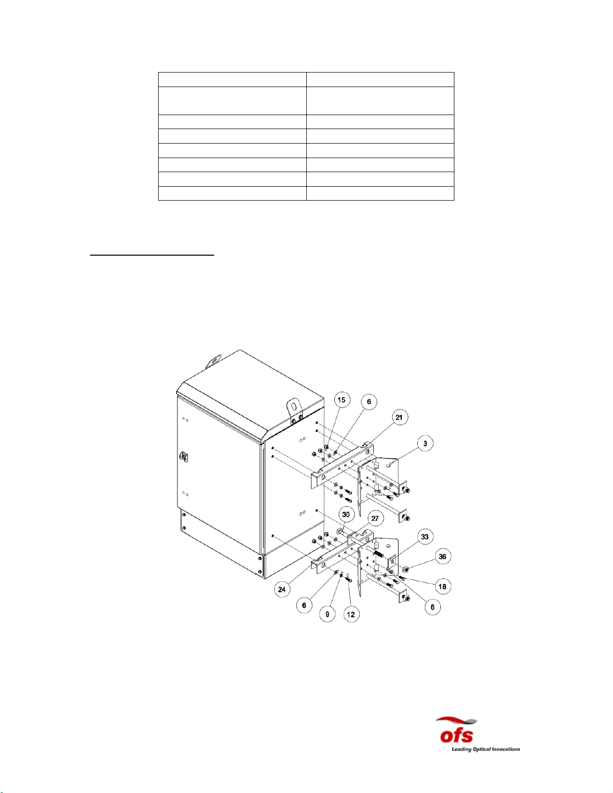
1. Pre-assemble the upper and lower horizontal brackets to the vertical brackets as
shown in the figures on the preceding pages.
2. Select a convenient mounting location on the pole.
3. Install the pole mounting template as an aid. Drill four (4) ¾” diameter holes in
the pole per the dimensions in Figure 7 for the four (4) 5/8” bolts (item 30 in
Figure 6).
4. Insert machine bolt (item 30) through mounting bracket and into the mounting
hole and press bolt and bracket flush against the pole.
5. Place round-cupped washer (item 33), with the concave side in, on bolt and finger
tighten nut.
6. Repeat step 4 and 5 for remaining bolts.
7. Secure the mounting bracket assemblies to the pole by securely tightening the
machine bolts to 40 ft-lbs for wooden posts.
8. Holes are provided in the side of the vertical brackets for lag bolt installation for
larger poles. The brackets can also be banded to metal poles.
9. Engage the four (4) 3/8” cap screws (item 12), which slide into the keyed slots
provided in the horizontal brackets, into the cabinet as shown in the diagram.
10. Using proper lifting and safety equipment, place cabinet on mounting bracket
assemblies using supplies 3/8” hardware and tighten to 45 ft-lbs. Lifting eyelets
are provided on the cabinet for hoisting it in place.

Issue2
November 14, 2011
- 10 -
11. Once cabinet is securely in place, install the remaining 3/8” cap screws (item 12)
on the upper pole mount bracket.
12. If the cable stubs connect to an underground cable, dress the cable down the pole.
If the cable stubs connect to an aerial cable, form a drip loop in the cable and
dress it up the pole to the splice case.
Pad Installation
Figure 8: 432 Cabinet Mounting Template

Issue2
November 14, 2011
- 11 -
Clearance Requirements
When selecting a location to mount the cabinet, ensure that proper clearance is available
to allow adequate ventilation and to allow the cabinet door to open fully. The cabinet
footprint with door open is shown below (from the top view).
Figure 10: Cabinet Footprint
The 432 Fiber Distribution Cabinet does not require the threading of input and output
cables through the base of the cabinet. The cable entry area can be found at the rear of
the cabinet. Removable panels are provided at the base of the cabinet, which allow the
cabinet to be slid over the input and output cables. Split seals can be slid over the cables
without threading the cables through the seals (see following figures).

Issue2
November 14, 2011
- 12 -
Figure 11: Cable Entry Area, Rear View
Figure 12: Top View of Cable Entry Area

Issue2
November 14, 2011
- 13 -
Pad Installation Procedures
Have the following equipment ready before beginning this procedure:
1. One masonry drill
2. One 5/8” (15.9 mm) masonry drill bit
3. Masonry expansion anchors
4. One 9/16” wrench
5. A pencil
6. One Hammer
Use the procedure below to mount the cabinet on an existing concrete slab.
1. Position the provided template on the slab in the desired location for the
cabinet and mark the location of the mounting holes with respect to the cable
entry area.
2. Place the template out of the way.
3. Drill 5/8” (15.9 mm) diameter by 3” (7.62 cm) deep holes at the locations
marked in step 2.
4. Insert anchor bolts into the holes in the slab and tap them firmly into the holes
with a hammer.
5. Remove the nuts and washers from the expansion anchors.
6. Remove the rear panels and seals from the cable entry area of the cabinet.
7. Remove the mounting bolt access covers from the plinth.
8. Place the cabinet over the studs and reinstall nuts and washers. Secure the
cabinet to the slab by securely tightening all anchor bolts to 40 ft-lbs or as
recommended by the expansion anchor manufacturer.
9. Reinstall the mounting bolt access covers on the plinth.
10. Remove portion of the cable entry seals corresponding to the diameters of the
cables. Install the split cable seals around the cables and slide them down the
cables to the base of the cabinet.
11. Reinstall the cable entry panels.

Issue2
November 14, 2011
- 14 -
Cabinet Grounding Information
Bonding and grounding should be done in accordance with the operating telephone
company’s standard procedures and comply with local electrical codes.
Ground Wire
The ground wire protects the electronics from voltage surges. A #6 ground wire must be
properly grounded to provide lightning surge protection for the cabinet. Please follow
this practice for attaching the ground unless local policies dictate otherwise.
For safety and performance reasons it is imperative that a cabinet be properly grounded.
The following guidelines should be used to ground the cabinet unless local practices,
rules, or regulations dictate otherwise.
Each door and equipment rack is grounded to the cabinet frame. The cabinet frame is
connected to the internal grounding bus by a stranded wire. A similar ground wire must
be used to connect the ground bus to each equipment ground lug. These ground wires
may need to be removed temporarily to troubleshoot ground faults. The wire may be
removed by unscrewing the screws that secure the green wire to the ground bus. Be sure
to reattach these wires after troubleshooting and resolving any ground conflicts.
Be sure to ground the cabinet before connecting power to the cabinet. This grounding
must be in effect at all times to safeguard personnel.

Issue2
November 14, 2011
- 15 -
Installation Procedures
Figure 13: Grounding Diagram
To ground the cabinet, use the following procedures and diagram above (Figure 13):
1. Drive the ground rods into the ground near the cabinet location.
2. Use a Megger-type Ohmeter to measure the resistance between the cabinet
ground and the ground rods. The resistance must be 25 ohms or less.
3. If the ohm requirement in step 3 is met, please proceed to step 4. Otherwise,
follow local practices to lower the resistance to ground to comply with 25
ohms before proceeding to step 4.
4. Connect a #6 ground wire to the ground rods.

Issue2
November 14, 2011
- 16 -
Fiber Routing
Fig. 14 432 Fiber Distribution Cabinet –Fiber routing
When routing the pigtails optimize the cable slack by choosing appropriate bend control
guides. Avoid cable kinking and pulling during the installation. Use the shelves and the
rings for keeping the pigtails organized.
Fiber Pass Trough
Parking

Issue2
November 14, 2011
- 17 -
Vault Options:
Consult your local distributor for various handhole/vault options.
Current compatible vaults can be found at:
Hubbell/Strongwell
PG3636Z514 Vault for 432 Fiber Distribution Cabinet
3621 Industrial Park Dr
Lenoir City, TN 37771
(865) 986-9726
Carson Industries
3048 PC- Undercover Vault for 432 Fiber Distribution Cabinet
1160 Nicole Court
Glendora, CA 91760
(909) 592-6272
Customer Information and Assistance
Ordering Entry/Customer Service 1-888-342-3743, Prompt 1
Sales Support 1-888-342-3743, Prompt 2
Technical Support 1-888-342-3743, Prompt 3
Please feel free to contact your Customer Service Representative for any product related
issues. Please make available OFS order number, part numbers, and company
information at the time of contact.
Table of contents
Other Ofs Indoor Furnishing manuals

Ofs
Ofs Heya User manual

Ofs
Ofs Riff Series User manual

Ofs
Ofs Kintra User manual

Ofs
Ofs ELEVEN COLLABORATIVE User manual

Ofs
Ofs Porter User manual

Ofs
Ofs Slate collaborative User manual

Ofs
Ofs LeanTo User manual

Ofs
Ofs Kintra User manual

Ofs
Ofs LAUNCH LA-24358CT User manual

Ofs
Ofs Electric Height Adjustable Tables User manual
Popular Indoor Furnishing manuals by other brands

Regency
Regency LWMS3015 Assembly instructions

Furniture of America
Furniture of America CM7751C Assembly instructions

Safavieh Furniture
Safavieh Furniture Estella CNS5731 manual

PLACES OF STYLE
PLACES OF STYLE Ovalfuss Assembly instruction

Trasman
Trasman 1138 Bo1 Assembly manual

Costway
Costway JV10856 manual