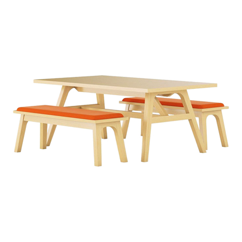
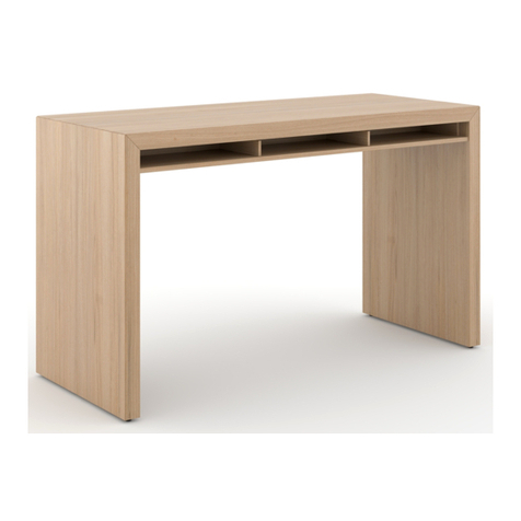
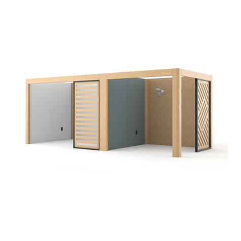
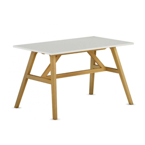
Ofs LAUNCH LA-24358CT User manual

LAUNCH
ASSEMBLY INSTRUCTIONS

Launch by OFS | 2
Checked by ______________________________ Checked by ______________________________ Checked by ______________________________
LA-24358CT TABLE COMPONENTS LA-21658CT TABLE COMPONENTS LA-18956CT TABLE COMPONENTS
Top 3 Sections Top 3 Sections Top 3 Sections
Bases (ordered separately) 2 Bases (ordered separately) 2 Bases (ordered separately) 2
Beams 2 Sets of 2 Beams 2 Sets of 2 Beams 2 Sets of 2
J-channel 2 J-channel 2 J-channel 2
Beam Brace 3 Beam Brace 2 Beam Brace 2
HK-106 (3" Lag Bolt with washer) 1 HK-106 (3” Lag Bolt with washer) 1 HK-106 (3” Lag Bolt with washer) 1
HK-6 (4"x4" Clamp Plate & Screws) 4 HK-6 (4"x4" Clamp Plate & Screws) 4 HK-6 (4"x4" Clamp Plate & Screws) 4
HK-7 (3"x3/4" Clamp Plate & Screws) 4 HK-7 (3"x3/4" Clamp Plate & Screws) 4 HK-7 (3"x3/4" Clamp Plate & Screws) 4
HK-10 (2 1/2" L-Bracket & Screws) 8 HK-10 (2 1/2" L-Bracket & Screws) 6 HK-10 (2 1/2" L-Bracket & Screws) 6
HK-68 (#8x1" Flat Head Screws) 3 HK-68 (#8x1" Flat Head Screws) 2 HK-68 (#8x1" Flat Head Screws) 2
HK-58 (#10x7/8" Pan Head Screws) 3 HK-58 (#10x7/8" Pan Head Screws) 3 HK-58 (#10x7/8" Pan Head Screws) 3
LA-24358CT POWER/DATA COMPONENTS LA-21658CT POWER/DATA COMPONENTS LA-18956CT POWER/DATA COMPONENTS
First Box Power/Data (CT4) 1 First Box Power/Data (CT4) 1 First Box Power/Data (CT4) 1
Power/Data Box (CT4) 7 Power/Data Box (CT4) 6 Power/Data Box (CT4) 5
(non CT4) (8) (non CT4) (7) (non CT4) (6)
Handy Box with plug-in cord 1 Handy Box with plug-in cord 1 Handy Box with plug-in cord 1
T-connector power cables 8 T-connector power cables 7 T-connector power cables 6
Velcro Cord Managers 10 Velcro Cord Managers 10 Velcro Cord Managers 10
Wiring harness for lights (CT4) 2 Wiring harness for lights (CT4) 2 Wiring harness for lights (CT4) 2
Transformer (CT4) 2 Transformer (CT4) 2 Transformer (CT4) 2
Transformer Power Service (CT4) 1 Transformer Power Service (CT4) 1 Transformer Power Service (CT4) 1
Light Cover Lenses (CT4) 14 Light Cover Lenses (CT4) 12 Light Cover Lenses (CT4) 10
HK-37 (#10-x 3/4” Quad Pan DT) 8 HK-37 (#10-x 3/4” Quad Pan DT) 7 HK-37 (#10-x 3/4” Quad Pan DT) 6
Checked by ______________________________ Checked by ______________________________ Checked by ______________________________
LA-16254CT TABLE COMPONENTS LA-13552CT TABLE COMPONENTS LA-10850CT TABLE COMPONENTS
Top 3 Sections Top 3 Sections Top 3 Sections
Bases (ordered separately) 2 Bases (ordered separately) 2 Bases (ordered separately) 2
Beams 2 Sets of 2 Beams 2 Beams 2
J-channel 2 Beam Brace 1 HK-106 (3” Lag Bolt with washer) 1
Beam Brace 2 HK-106 (3” Lag Bolt with washer) 1 HK-10 (2 1/2” L-Bracket & Screws) 2
HK-106 (3” Lag Bolt with washer) 1 HK-6 (4"x4" Clamp Plate & Screws) 4
HK-6 (4"x4" Clamp Plate & Screws) 4 HK-7 (3"x3/4" Clamp Plate & Screws) 4
HK-7 (3"x3/4" Clamp Plate & Screws) 4 HK-10 (2 1/2" L-Bracket & Screws) 4
HK-10 (2 1/2" L-Bracket & Screws) 4 HK-68 (#8x1" Flat Head Screws) 1
HK-68 (#8x1" Flat Head Screws) 2
HK-58 (#10x7/8" Pan Head Screws) 3
LA-16254CT POWER/DATA COMPONENTS LA-13552CT POWER/DATA COMPONENTS LA-10850CT POWER/DATA COMPONENTS
First Box Power/Data (CT4) 1 First Box Power/Data (CT4) 1 First Box Power/Data (CT4) 1
Power/Data Box (CT4) 4 Power/Data Box (CT4) 3 Power/Data Box (CT4) 2
(non CT4) (5) (non CT4) (4) (non CT4) (3)
Handy Box with plug-in cord 1 Handy Box with plug-in cord 1 Handy Box with plug-in cord 1
T-connector power cables 5 T-connector power cables 4 T-connector power cables 3
Velcro Cord Managers 10 Velcro Cord Managers 10 Velcro Cord Managers 10
Wiring harness for lights (CT4) 2 Wiring harness for lights (CT4) 1 Wiring harness for lights (CT4) 1
Transformer (CT4) 2 Transformer (CT4) 1 Transformer (CT4) 1
Transformer Power Service (CT4) 1 Transformer Power Service (CT4) 1 Transformer Power Service (CT4) 1
Light Cover Lenses (CT4) 8 Light Cover Lenses (CT4) 6 Light Cover Lenses (CT4) 4
HK-37 (#10-x 3/4” Quad Pan DT) 5 HK-37 (#10-x 3/4” Quad Pan DT) 4 HK-37 (#10-x 3/4” Quad Pan DT) 3
Launch by OFS | 3
LAUNCH
Note: Illustrations display model LA-24358CT.
Any variations in assembly for smaller models will be noted in the text.
INSTALLATION TIPS
1. Table will be too heavy to move after assembly. Be sure table base and beam
assembly is in desired location and is level. See page 4, Step 2.
2. Table section with end opening labeled “A” must be over power source when
powered through end of table. See page 5, Step 4.
3. First Box must always be installed at end of table. Match Box labeled “A” to opening
labeled “A”. See page 12, Step 1.
4. When placing Power/Data boxes into table male end of T-connector must point
towards First Box. See page 12, Step 1.
5. Power/Data boxes must be secured with brackets or warranty will be voided. See
page 12, Step 2.
6. Center powered tables requires additonal splitter. See page 14.

Launch by OFS | 4
LAUNCH
STEP 1 - BEAM ASSEMBLY
Note: Skip this step if assembling models
LA-10850CT or LA-13552CT.
1. Place beams veneer side down on soft surface (to prevent
scratching).
2. Beams should be end to end, bored ends to the outside, with
no gap between the beems.
3. Align grooves on the beams and slide the J-channel until it is
centered on the two beams.
4. Screw J-channel to beams using twenty-four (24) pan head
#10x7/8" screws (HK-58) on each J-channel.
STEP 2 - BASE PLACEMENT
1. Place bases in desired location. If assembling a table with
Power/Data option, base should be placed over Power/Data
outlets.
2. Place beams inside of opening so there is no gap between the
beam and the mending plate on the base. The J-channel edge
of the beam should be towards the floor.
3. Using a 3/16" drill bit, pre-drill holes for the lag bolts
(HK-106) through the beam into the base.
4. Drive lag bolts through the beams into the base and tighten
securely.
5. Level the base beam assembly at this time. Level should only
be placed on mending plates while leveling since a “crown” is
built into the beams.

Launch by OFS | 5
Note: Illustrations display model LA-24358CT. Any variations in assembly for smaller models will be noted in the text.
LAUNCH
STEP 3 - BRACE PLACEMENT
Note: Model LA-10850CT will not have any beam braces.
1. Place beam braces between beams so that they are spaced
out evenly. DO NOT screw into place. Braces will be adjusted
and fastened later.
STEP 4 - TOP PLACEMENT
Note: Model LA-10850CT is a one piece top.
1. Place top sections on base/beam assembly as shown.
2. If using Power/Data boxes, the table section with end opening
labeled “A” must be over power source (Does not apply to
Center Powered tables).

Launch by OFS | 6
LAUNCH
STEP 5 - BRACE ADJUSTMENT
1. Adjust location of all beam braces to rest inside of recessed
pockets on underside of top.
STEP 6 - SECURE TOP SECTIONS
Note: Model LA-10850CT is a one piece top and does not use
4"x 4"clamp plates.
1. Pull top sections together leaving no gap between top
sections.
2. Secure top sections together using four (4) 4" x 4" clamp
plates (HK-6).
3. Use eight (8) #8 x 3/4" flat head screws (HK-6) on each clamp
plate.

Launch by OFS | 7
Note: Illustrations display model LA-24358CT. Any variations in assembly for smaller models will be noted in the text.
LAUNCH
STEP 7 - TOP ADJUSTMENT
1. Adjust top location so there is an equal distance from each
base to the edge of the top.
STEP 8 - TOP PLACEMENT
1. Attach top to base by using eight (8) #8 x 1 1/2" pan head
screws (HK-15) on each base.
2. Attach top to braces by using eight (8) #8 x 1" flat head screws
(HK-68) on each brace.
Equal Distances
#8 x 1” Flat Head
#8 x 1 1/2” Pan Head

Launch by OFS | 8
LAUNCH
STEP 9 - BRACE TO BEAM ATTACHMENT
Note: Model LA-10850CT and LA-13552CT do not have J-channels
and do not require pre-drilling.
1. Where braces are located between J-channels, pre-drill with
1/8" drill bit through J-channel.
2. Attach brace to beam by using four (4) #8 x 1" flat head
screws (HK-68) on each brace.
STEP 10 - L-BRACKET ATTACHMENT
1. Space out 2 1/2" L-brackets evenly between bases and beam
braces.
2. Attach L-brackets by using four (4) #10 x 5/8" pan head
screws (HK-10) on each L-bracket.
Pre-Drill Here

Launch by OFS | 9
Note: Illustrations display model LA-24358CT. Any variations in assembly for smaller models will be noted in the text.
LAUNCH
STEP 11 - TOP ADJUSTMENT
Note: Some model LA-10850CT’s are one piece tops and do not
use 3"x 3/4"clamp plates.
1. To ensure top sections are flush to each other, use 3" x 3/4"
clamp plate (HK-7) on each joint just outside of 4" x 4" clamp
plates.
2. Attach clamp plates to top by using four (4) #8 x 5/8" pan head
screws (HK-7) on each clamp plate.

Launch by OFS | 10
LAUNCH POWER PARTS
HANDY BOX
Plugs into floor outlet. Connected to first box by T-connector cable.
Qualified electrician can remove plugs and directly hard wire unit.
FIRST BOX
For Center Powered table, see page 14.
When the power source for the table is under the base, power
from the Handy Box enters this box first. On the CT4 models, the
First Box contains the light switch. On the CT4 models, the wiring
harness for the lights always plugs into the First Box.
CT4 Model Shown T-Connector

Launch by OFS | 11
LAUNCH POWER PARTS
STANDARD POWER/DATA BOX
T-Connector cable plugs in one side, another cable plugs in the
other side and goes to the next box.
T-CONNECTOR POWER CABLE (A)
Snaps between Power/Data boxes.
TABLE LIGHT POWER SOURCE (B)
Supplies power from First Box to Transformer(s).
TRANSFORMER (CT4 MODELS ONLY) (C)
Plugs into table light power source and supplies power to wiring
harness(es).
WIRING HARNESS (CT4 MODELS ONLY) (D)
Plugs into Transformer and supplies power to all lights in table top.
-- For tables 108" to 189" --
One transformer and one harness are required for setup.
-- For tables 216" to 243" --
Two transformers and two harnesses are required for setup, one
on each side of the table top.
A
C
B
D

Launch by OFS | 12Launch by OFS | 12
LAUNCH POWER ASSEMBLY
STEP 1 - POWER/DATA BOX PLACEMENT
1. Locate First Box labeled “A” and insert in top at end of table
(opening “A”) over power source. If power source is in the
center of the table, then the First Box must still be placed
at the end of the table. T-connector MUST be positioned as
shown in the illustration.
2. When placing additional boxes into table, male end of
T-connectors MUST point towards First Box.
3. Place additional boxes into remaining openings, matching
labels on boxes to labels on openings.
STEP 2 - SECURE POWER/DATA BOXES
IMPORTANT: Brackets must be correctly installed or warranty will
be voided due to possible damage to top or Power/Data Boxes.
1. Hold Power/Data Box bracket against side of Power/Data Box
and insert machine screws (shipped with Power/Data box)
through slot and into machined hole in sides of boxes.
DO NOT tighten machine screws.
2. Slide bracket tight against underside of top and screw into
place using 2 (or 4) #10 x 3/4" quad pan head screws (HK-37)
per bracket.
3. Position box flush to worksurface and tighten machine
screws.
STEP 3 - CONNECT HANDY BOX
For Center Powered table, see page 14.
1. Place Handy Box with plug-in cords inside of base.
2. Plug male end of T-connector power cable into Handy Box.
3. Plug female end of T-connector power cable into First Box.
Table Base Other Boxes

Launch by OFS | 13
LAUNCH POWER ASSEMBLY
STEP 4 - INSTALL WIRING HARNESS (CT4 MODEL ONLY)
1. Snake wiring harness between beams and through beam
braces so single wire male connector end of harness is in
proximity of the First Box.
2. Each pair of lights plugs into a pair of matching plugs on
wiring harness(es). Connect lights to harness pushing plugs
together to lock.
STEP 5 - (CT4 MODEL ONLY)
1. Plug table light power source into switch house of First Box.
2. Plug transformer(s) into table light power source.
3. Plug wiring harness(s) into transformer(s).
STEP 6 - CONNECT POWER/DATA BOXES
1. Plug male end of T-connector power cable into First Box.
2. Plug female end of T-connector power cable into adjacent
box.
3. Continue for all Power/Data Boxes.
STEP 7
1. Plug Handy Box into floor outlet.

Launch by OFS | 14
LAUNCH POWER ASSEMBLY
FOR CENTER POWERED TABLES ONLY
1. Find the Splitter that is shipped with the Center Wire
Management Column and attach to Power/Data Box closest to
floor outlet.
2. Place Handy Box with plug-in cords inside of Center Wire
Management Column.
3. Plug male end of T-connector power cable into Handy Box.
4. Plug female end of T-connector power cable into Splitter.
5. Plug in T-connector Power Cables from center of table out to
ends of table.


01.17
an OFS Brands™company | 1204 East Sixth Street | Huntingburg, IN 47542 | 800-521-5381 | ofs.com
This manual suits for next models
5
Table of contents
Other Ofs Indoor Furnishing manuals

Ofs
Ofs Porter User manual

Ofs
Ofs Kintra User manual

Ofs
Ofs Slate collaborative User manual

Ofs
Ofs Riff User manual

Ofs
Ofs ELEVEN COLLABORATIVE User manual

Ofs
Ofs Staks benching assembly User manual

Ofs
Ofs Edward Jones BOA User manual

Ofs
Ofs Kintra User manual

Ofs
Ofs LeanTo User manual

Ofs
Ofs APTOS User manual
Popular Indoor Furnishing manuals by other brands

Furinno
Furinno NT-12034 Assembly instruction

Furniture of America
Furniture of America FOA-DK915 Assembly instructions

Costco
Costco 1500058 Assembly / care & use instructions

FIAM.
FIAM. SHELL 051 Product information

Wilhelm Schildmeyer
Wilhelm Schildmeyer 566185 Assembly instructions

Canvas
Canvas PALMA 088-0743-4 Assembly instructions