RECTANGULAR LEG
SQUARE LEG
SQUARE LEG
RECTANGULAR LEG
ELECTRIC ADJUSTABLE HEIGHT
BASE ASSEMBLY
RECTANGULAR OR SQUARE COLUMNS
Attach mounting hardware to
•
top of columns.
Use (6) M6x 12MM socket head
•
cap screws, per column, to attach
L-brackets to themotor housing
on the rectangular column.
Use (4) M6 x 16MM at head
•
cap screws, per column ,to
attach mounting plate to top
of column.
Place work surface bottom side
•
up on a non-marring surface.
Align holes on mounting plate
•
with pre-drilled holes on bottom
side of work surface.
Fasten mounting hardware to
•
worksurface using (8) #12 X 1"
truss head screws per column.
Series:
Part #:
RECTANGULAR LEG
SQUARE LEG
SQUARE LEG
RECTANGULAR LEG
ELECTRIC ADJUSTABLE HEIGHT
BASE ASSEMBLY
RECTANGULAR OR SQUARE COLUMNS
Attach mounting hardware to
•
top of columns.
Use (6) M6x 12MM socket head
•
cap screws, per column, to attach
L-brackets to themotor housing
on the rectangular column.
Use (4) M6 x 16MM at head
•
cap screws, per column ,to
attach mounting plate to top
of column.
Place work surface bottom side
•
up on a non-marring surface.
Align holes on mounting plate
•
with pre-drilled holes on bottom
side of work surface.
Fasten mounting hardware to
•
worksurface using (8) #12 X 1"
truss head screws per column.
Series:
Part #:
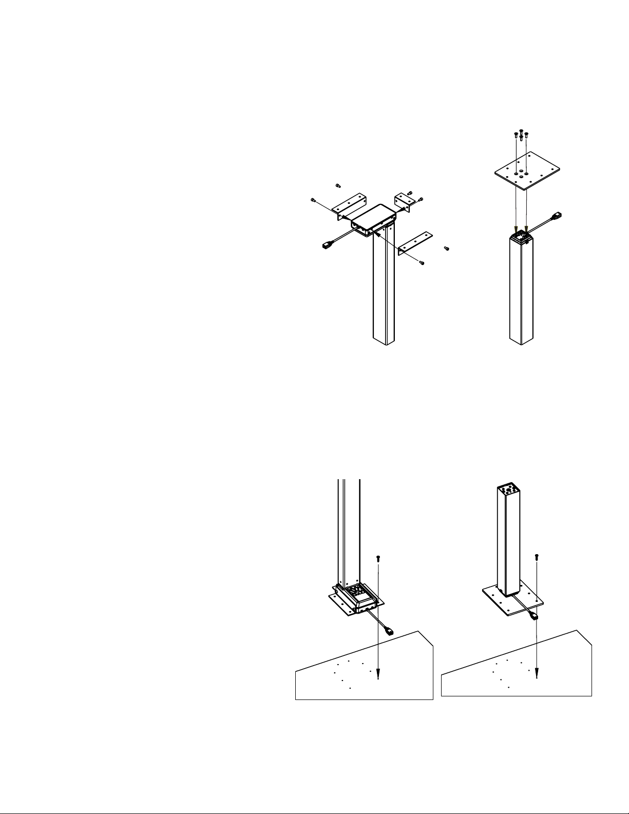
Rectangular or Square Columns
1. Attach mounting hardware to top of columns.
2. Use (6) M6 x 12MM socket head cap screws,
per column, to attach L-brackets to the motor
housing on the rectangular column using a
5mm allen wrench.
3. Use (4) M6 x 16MM flat head cap screws, per
column, to attach mounting plate to top of
column using a 5mm allen wrench.
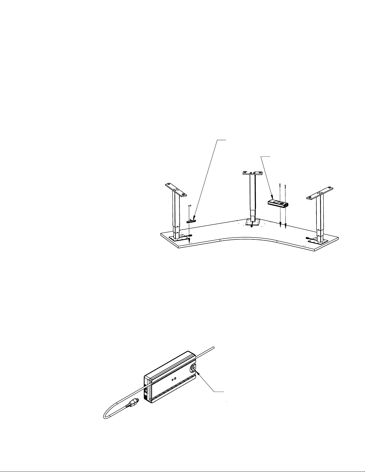
4. Place worksurface bottom side up on a non-
marring surface.
5. Align holes on mounting plate with pre-drilled
holes on bottom side of worksurface.
6. Using a phillips head on the cordless
screwdriver, fasten mounting hardware to
worksurface using (8) #12 X 1” truss head
screws per column.
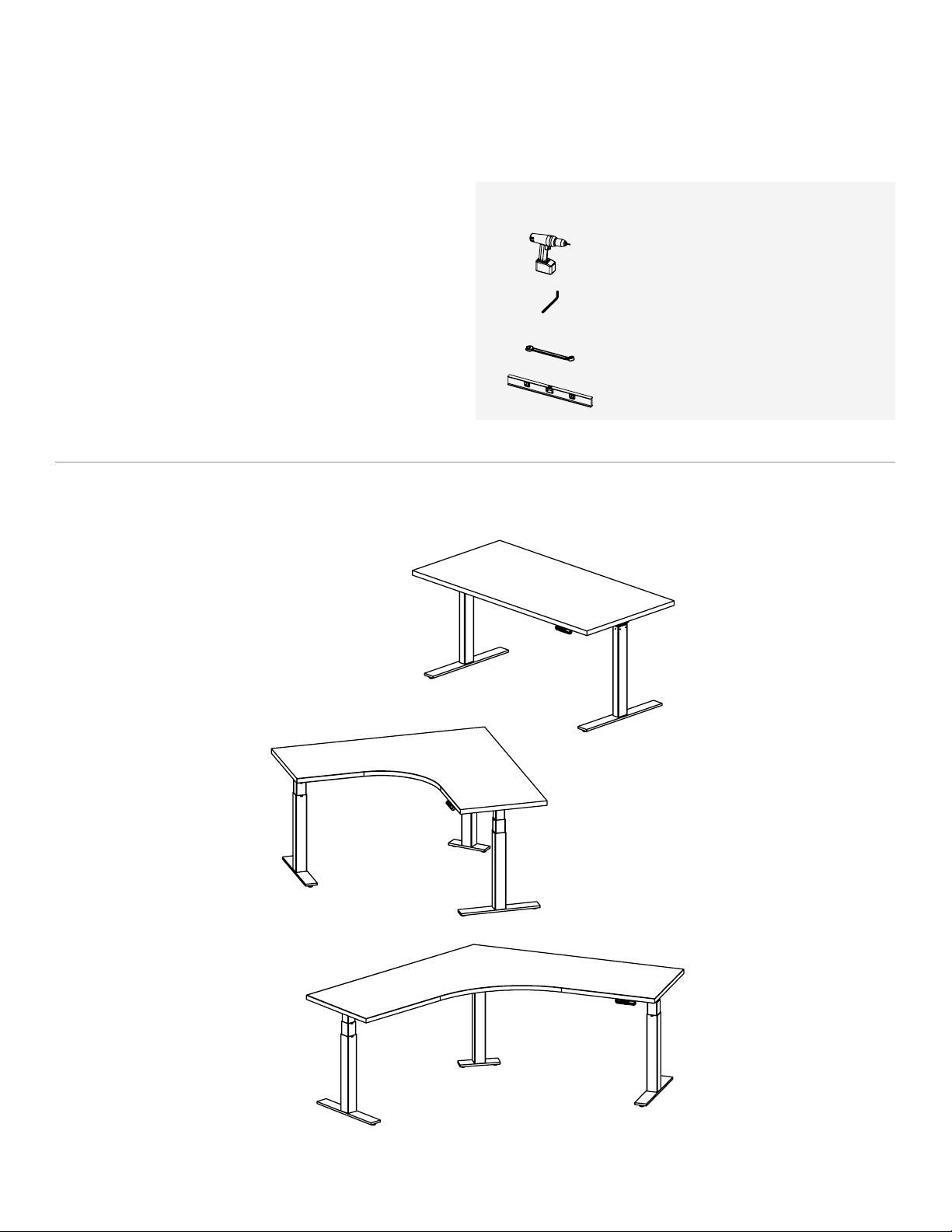
Electric Height Adjustable Tables
ASSEMBLY INSTRUCTIONS
4 | OFS BRANDS
RECTANGULAR
LEG
RECTANGULAR
LEG
SQUARE
LEG
SQUARE
LEG