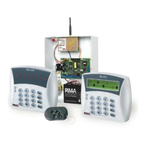
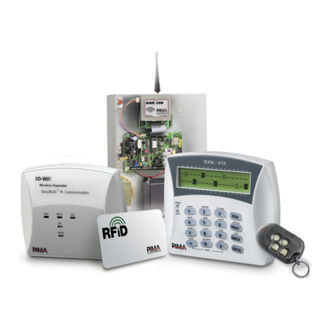
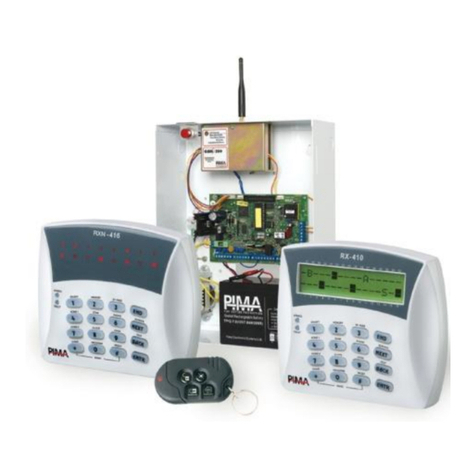
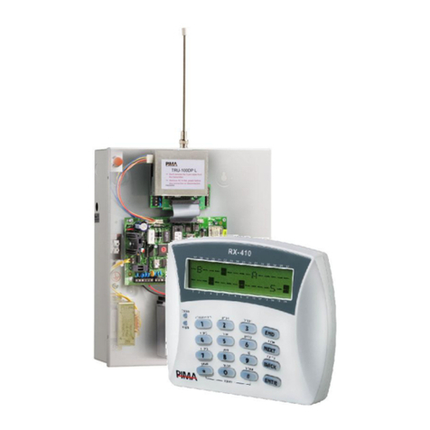
Pima CAPTAIN-i 4410061 User manual

PIMA Electronic Systems Ltd.
www.pima-alarms.com
Part No:
4410061
XX en Rev: K
October 2008
CAPTAIN-i
6ZONES INTRUDER ALARM SYSTEM
INSTALLATION GUIDE
System ver. 6.0

2 Captain-i - Installation Guide
PIMA Electronic Systems Ltd. does not represent that its Product may not be compromised
and/or circumvented, or that the Product will prevent any death, personal and/or bodily injury
and/or damage to property resulting from burglary, robbery, fire or otherwise, or that the
Product will in all cases provide adequate warning or protection. The User understands that a
properly installed and maintained equipment may only reduce the risk of events such as
burglary, robbery, and fire without warning, but it is not insurance or a guarantee that such will
not occur or that there will be no death, personal damage and/or damage to property as a result.
PIMA Electronic Systems Ltd. shall have no liability for any death, personal and/or bodily
injury and/or damage to property or other loss whether direct, indirect, incidental, consequential
or otherwise, based on a claim that the Product failed to function.
Warning: The user should follow the installation and operation instructions and among other
things test the Product and the whole system at least once a week. For various reasons,
including, but not limited to, changes in environment conditions, electric or electronic
disruptions and tampering, the Product may not perform as expected. The user is advised to
take all necessary precautions for his/her safety and the protection of his/her property.
This document may not be duplicated, circulated, altered, modified, translated, reduced to any
form or otherwise changed, unless PIMA’s prior written consent is granted.
All efforts have been made to ensure that the content of this manual is accurate. Pima retains
the right to modify this manual or any part thereof, from time to time, without serving any prior
notice of such modification.
Please read this manual in its entirety before attempting to program or operate your system.
Should you misunderstand any part of this manual, please contact the supplier or installer of this
system.
Copyright ©2008 by PIMA Electronic Systems Ltd. All rights reserved.
Contact us:
PIMA Electronic Systems LTD
Tel.: +972.3.6506414
Fax: +972.3.5500442
Email: support@pima-alarms.com
Web: http://www.pima-alarms.com
Default codes:
Master code: 5555
Technician code: 1234

Captain-i - Installation Guide 3
Table of Contents
Chap 1. Introduction..................................................................................... 5
1.1 Release Note - Version 6.0 ................................................................5
1.2 Main features...................................................................................6
1.3 The Dialer........................................................................................6
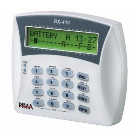
1.4 The LCD Keypad...............................................................................7
1.5 The PCB ..........................................................................................7
Chap 2. Partitions ......................................................................................... 9
Chap 3. Connecting Accessories................................................................. 10
3.1 Zone Inputs ...................................................................................10
3.2 Initial operations & Programming devices .........................................16
Chap 4. Programming Options ................................................................... 17
4.1 Remote Programming with COMAX .................................................. 17
4.2 PRG-22: Local Programmer .............................................................17
4.3 LCL-11A: Adaptor for Local Programming .........................................18
4.4 Programming with an LCD Keypad ...................................................18
Chap 5. Programming ................................................................................. 21
5.2 Communication Parameters.............................................................23
5.3 GSM-200 .......................................................................................26
5.4 Programming System Characteristics................................................29
5.5 General Issues ...............................................................................36
Chap 6. Faults and Troubleshooting........................................................... 38
6.1 General .........................................................................................38
6.2 Faults Displayed on the LCD Keypad ................................................38
6.3 Retrieving the Primary Code ............................................................39
6.4 Troubleshooting .............................................................................39
Chap 7. Accessories .................................................................................... 42
7.1 PRG-22 fast programmer.................................................................42
7.2 LCL-11A programming adaptor unit..................................................42
7.3 MIC-200 microphone unit................................................................42
7.4 VU-20N Voice unit ..........................................................................42
7.5 Long-range radio transmitter...........................................................42
7.6 GSM-200 Cellular Transmitter .......................................................... 43
7.7 Keypads ........................................................................................43
Appendix A – Default system parameters ................................................. 44
1. Zones............................................................................................44
2. Codes and delays ...........................................................................44
3. Siren outputs .................................................................................44
4. System configuration, general parameters ........................................44
5. Telephones dialer to subscriber........................................................45
6. System responses to events ............................................................45
7. Monitoring station ..........................................................................46
4 Captain-i - Installation Guide
8. Reporting codes (phone).................................................................46
9. Reporting codes (radio) ..................................................................47
Appendix B – Programming formats ......................................................... 48
1. Pulse formats.................................................................................48
2. DTMF formats ................................................................................49
Appendix C – Entering names .................................................................... 51

Captain-i - Installation Guide 5
Chap 1. Introduction
This guide provides the installation, wiring and programming instructions for PIMA’s
CAPTAIN-i intruder alarm system. CAPTAIN-i has many features that fits customer’s
individual needs, and yet it remains easy to install and simple to program and use,
both by the end-user and the installer.
CAPTAIN-i is secured against radio-frequency (RF) interferences and electro-magnetic
interferences (EMI).
Safety Instructions
Your CAPTAIN-i Alarm System has been registered in accordance with EN60950
and its rules. EN 60950 requires us to advise you the following information:
1. In this alarm system hazards of fire and electric shock exist. To reduce the risk of
fire or electric shock, do not expose this alarm system to rain or moisture. Pay
attention: Telephone cords could be a good conductor for lightings energy.
2. Do not open the door of the alarm system. Dangerous high voltages are present
inside of the enclosure. Refer servicing to qualified personnel only.
3. This alarm system should be used with AC 230V/110V, 50Hz, protected by anti
electric shock breaker. To prevent electric shocks and fire hazards, do NOT use
any other power source.
4. Do not spill liquid of any kind onto the unit. If liquid is accidentally spilled onto the
unit, immediately consult a qualified service.
5. Install this product in a protected location where no one can trip over any line or
power cord. Protect cords from damage or abrasion.
6. Disconnect all sources of power supply before proceeding with the installation. Pay
attention: do not install low voltage wires near by AC power wires they should be
separated.
7. Connect the AC transformer output to the terminal block on the control panel as
marked.
8. Connect the AC line cord to line power terminals as marked. (GND; N; L)
Important! Regarding parameters such as Date and Time, User codes and
Telephone numbers, refer to the CAPTAIN-i’s User Guide.
1.1 Release Note - Version 6.0
<New> PCB with a new jumper - JP3 - that is set according to the EOLs
<New> GSM-200 module connectivity
<New> VU-20N voice unit

6 Captain-i - Installation Guide
1.2 Main features
♦6 zone intruder alarm panel
♦Can be divided to 2 partitions
♦Up to 4 telephone numbers to the Monitoring Station and 3 to private numbers
♦Easy to install and simple to program and use
♦Various ways for arming and disarming: keypad, key, remote control &
auto-arming
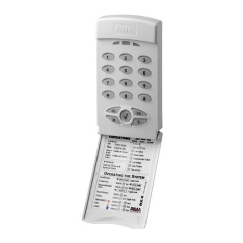
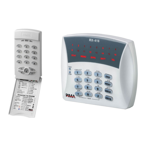
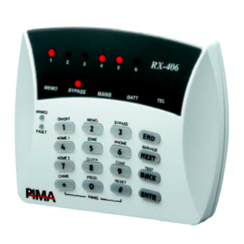
♦Two types of keypads: LCD (RXN-400/410), LED (RX-6/406)
♦Can monitor up to 6 keypads
♦Two operating modes: Full or Home
♦System events are registered in non-volatile memory
♦Various operating codes: Master Codes, 8 User codes, Short code for arming
♦User Code #8 can serve as Panic code
♦Temporary bypass of zones
♦“Chime” mode per zone: the keypad buzzer indicates when a zone is opened
♦Monitoring Station communicator: built-in dialer, integrated long-range radio
transmitter and cellular transmitter
♦Inhibits system from arming in case of failure
♦Two keys combination for DURESS and FIRE codes
1.3 The Dialer
CAPTAIN-i includes alarm dialer that is capable of calling 3 private numbers
(programmed by the customer) via PSTN network or GSM transmitter1.
Note: It is advisable to assign a name, e.g. “Alarm at XXX” when calling a telephone
with caller ID.
The dialer calls these numbers to report on alarms, faults etc. It calls each subscriber
twice and sounds an alarm tone. If the system includes a voice unit the dialer will not
sound an alarm tone, but a recorded voice message.
The dialer terminates the calling cycle in the following circumstances:
The system was disarmed
All calls to the subscribers were completed (two calls to each subscriber)
1Private dialer via GSM-200 transmitter is supported with CAPTAIN-i version 5.5 and up.

Captain-i - Installation Guide 7
1.4 The LCD Keypad
CAPTAIN-i is fully controlled by the LCD keypad.
1.5 The PCB
CAPTAIN-i PCB
1.5.1 Fuses
♦F1 - Siren power supply (0.9A)
♦F2 - Keypad and detectors power supply (750mA). This fuse protects all
the (+V) outputs
♦F3 - Battery
♦F4 - Transformer
1.5.2 Connection terminals
♦AC Voltage Input: 14-16 VAC (+/- 10%) input from the transformer. The cross-
section area of the main AC cable must be at least 0.75mm2
♦Connection to Backup Battery: Red wire for the positive (+) contact; Black
wire for the negative (-) contact.
IMPORTANT! Wrong connection of battery contacts can damage the PCB

8 Captain-i - Installation Guide
♦Z1-Z6: Zones Inputs: Inputs for dry contact detectors from any zone, including
EOL protected.
♦(+V): Detectors Voltage: Power supply output for PIR detectors, ultrasonic
detectors, etc. The output is protected by F2 thermal fuse (protects the keyboard
too)
♦SMOKE: Voltage Output for Smoke Detectors: The output is switched to
minus (-) when smoke alarm occurs, for resetting the smoke detectors. When a
zone programmed to “Fire” response is activated, its power is temporarily
disconnected.
To manually reset the output, press long .
SMOKE output can be programmed to work inversely, i.e. disconnected in normal
mode and switched to (–) when activated.
♦PGM: Auxiliary Output: This output can be programmed either to be
disconnected or to be switched to GND, in case of alarm (see sections 5.4.4 and
5.4.6 ). MIC-200 microphone or VU-20N voice Unit can be connected to this
output.
♦SRN: Siren Output: Two sirens (with or without a driver) can be connected to
this output in parallel (See section 3.1.5). F1 thermal fuse protects it.
♦KEYPAD: Keypads Connection: The output has four terminals: (+V), (–), IN
(data), OUT (data). F2 thermal fuse protects the voltage supply (together with
detectors voltage).
The system can have up to 6 keypads connected to it.
Notes:
All PIMA LED keypads can be connected to the system.
Do not connect anything but keypads to the keypad power source
connectors
♦SRN: Siren Output: Two sirens (with or without driver) in parallel can be
connected to this output (See section “3.1.5”). F1 thermal fuse protects it.
♦AUD: Connection to Microphone or Voice Unit: See sections 3.1.8, 3.1.9 and
5.1.3.
♦LINE: Connections to Telephone Line: It is recommended to connect the
inputs as close as possible to the line source to prevent tampering
♦SET: Connections to Telephone Sets: Terminals for connecting fax, answering
machine, telephones etc.
♦P1: Transmitter: A quick connector for RF and GSM transmitters
♦P2: Keypad: A quick connector to connect a technician keypad
For setting the jumpers, see page 12.

Captain-i - Installation Guide 9
Chap 2. Partitions
CAPTAIN-i can be configured into 2 partitions with the following settings:
1. Each zone and each user can be assigned to one of the two partitions or both
2. Each partition can have a different subscriber (account) ID
3. All keypads connected to the system show the same display, regardless their
partition.
For additional information:
To assign zones to partitions: see section 5.1.3
To program subscriber (account) ID: see section 5.2.5
To assign users to partitions: see section 5.4.11
See “CAPTAIN-i User Guide” for information on keypads display and partitions

10 Captain-i - Installation Guide
Chap 3. Connecting Accessories
IMPORTANT! Disconnect all power supply before installation
Connecting accessories scheme (optional)
3.1 Zone Inputs
Any zone connected to the system can be set as EOL zone.
Note: CAPTAIN-i can only be set as an EOL (one or two) protected system, and not
each zone separately, i.e., all zones are set as EOL zones.
3.1.1 Zones without EOL
+
TAMPER RELAY
Detector
Zone
Control
Panel ()
+
TAMPER RELAY
Detector
Tamper
Switch
()
Zone
()
Tamper connected in
serial to the zone relay
The PIR relay and the tamper are
connected separately; Tamper is
connected to 24H Zone
3.1.2 Single EOL protected zones
EOL resistor values in the following schemes are:
R1: 13KΩ or 6.8KΩ
R2: 10KΩ
R3: 5.1KΩ
All resistors are of ¼W

Captain-i - Installation Guide 11
3.1.2.1 N.C. PIR
N.C.
Detector
R1 or R3
Tamper
switch
Zone Control
Panel ()
+
TAMPER RELAY
Detector
Zone
Control
Panel ()
R1 or
R3
EOL connected to
N.C PIR
EOL in serial to a relay
(zone) and a tamper
The relay and the tamper are
connected, each with an EOL;
The tamper is connected to
24h Zone
3.1.2.2 N.O. PIR
Zone (-)
N.O. detector
Tamper
switch
R1 or R3
R1 or R3
+
TAMPER RELAY
Detector
Tamper
Switch
Control
Panel ()
R1 or R3
R1 or R3
+
TAMPER RELAY
Detector
Tamper
Switch
Zone
Control
Panel ()
Control
Panel ()
EOL connected to
N.O PIR
EOL connected in parallel to
the a relay (zone) and in
serial to a tamper
The relay and the tamper are
connected, each with an EOL;
The tamper is connected to
24h Zone
3.1.3 Two EOLs protected zones
3.1.3.1 N.C. PIR
Two EOL connected to
N.C PIR
Two EOLs connected to the relay
(zone) and in serial to the tamper

12 Captain-i - Installation Guide
3.1.4 Arming with key/Remote control
Connect the key or relay output of the remote control receiver to Zone 6 and GND.
Zone 6 must be programmed as normally open and as Key input (see section 5.4.4).
For better protection it is recommended to connect a 10KΩEOL resistor. The key can
be of momentary or latch position type (see section 5.4.4).
GND
Electrical Diagram
N.O. connection
Without EOL
resistor N.C. connection
R2
Key wiring
Notes:
When using EOL resistors, the input must be programmed accordingly (see section
5.1.2).
The key for the properties of Zone 6 may be set as either N.O. or N.C.
3.1.5 Sirens & Jumpers
3.1.5.1 Jumpers
♦JP1: Sets whether the output, when triggered, is switched to (V+) or (GND)
♦JP2: Sets whether the power source is stabilized or unregulated
♦JP3: Is set according to the EOL values
JP 1 & 2:
Jumper Pins Connection
JP1 Is switched to GND (-) (default)
Horn
siren
JP2 Has no effect (is bypassed)
JP1 Is switched to positive (+)
Stabilized up to 13.8V (default)
DC
siren JP2
Unregulated up to 20V
Protected with
0.9A thermal
fuse
JP3:
Pins Values
10k, 13k (default)
10k, 10k
Connected
EOLs
5.1k, 6.8k

Captain-i - Installation Guide 13
3.1.5.2 Horn
♦Connect the horn to the SRN and common (-) terminals
♦Program the siren tone (see section 5.4.1)
Horn (speaker siren)
3.1.5.3 Low current up to 200mA DC Siren
♦Connect the siren’s GND end to the SRN terminal and siren’s power to the
(+)V terminal
♦Program siren tone 9 (see section 5.4.1 on page 29)
Piezoelectric
siren
+V SMOKEPGM SRN
OUTPUTS
-+V IN OUT
KEYPAD
DC Siren
3.1.5.4 High current DC Siren
♦Connect the siren’s power end to the SRN terminal and the siren’s GND to the
common (-) terminal
♦Program tone 9 for the siren as described in 5.4.1.
-
6
+V SMOKEPGM SRN
OUTPUTS
-+V IN
O
KEYPAD
High Current Siren
Note: Unregulated siren consumes current from the control panel’s battery

14 Captain-i - Installation Guide
3.1.6 Keypad connection
Connect all 4 wires coming from the keypad ([-], +V, IN, OUT) to the keypad terminal
block.
IMPORTANT!
The keypad power should not be shared with any other device!
The keypad wires should not be passed through the same cable as
the telephone wires. Doing this may cause the keypad signal to
interfere with the telephone signal
3.1.7 Telephone
Connect the pair of wires coming from the telephone line to the LINE connection
terminals. Connect a telephone set to the SET terminals
Telephone Wiring
3.1.8 Microphone unit MIC-200
MIC-200 Wiring
1. In the “Zone Responses” screen (see page 22), program (+) under PGM for each
zone that will activate the MIC-200.
2. In the “System Configuration 3” (page 31) program (+) under the letter G (PGM
delayed).
Note: Do not program delayed PGM and delayed SMOKE for the same time. In case
both features are programmed together, the system will ignore delayed SMOKE

Captain-i - Installation Guide 15
3.1.9 Programming the VU-20N
1. Navigate to “System config 3” menu (#8) and mark ‘+’ under ‘V - Voice’ unit
and under ‘G - Delayed PGM
2. In Zone responses menu (#3), click the desired zone and mark ‘+’ under ‘P -
PGM’, so that the zone will trigger the PGM output (to which the VU-20N
connects) in alarm.
Captain-i
V
(+)
AUDIO
IN
VU-20N
GND
(-)
PGM
Blue
Red
Black
Green
Yellow
Loose
3.1.10 GSM-200 Cellular module
OUT LINE
AUD
IN
Orange
Yellow
TRANSMITTER
Captain-i
To connect GSM-200:
1. Connect the yellow wire to
AUD IN
2. Connect the orange wire to
AUD OUT
3.1.10.1 Connecting VU-20N with GSM-200 Cellular Transmitter
To connect VU-20N together with GSM-200, connect a 5.1 kΩresistor to one of the
VU-20N blue Audio wires (The second should remain loose).
3.1.11 Mains voltage
Notes:
The cross-section area of the AC main cable must be at least 0.75 mm2
The hole through which the main cable passes must have either a grommet or
bushing
The wires of the main cable must be tied together with cable tie. The flammability
of the cable tie must be UL 94 V-2 or better
The system should be connected to an automatic circuit breaker that cuts off the
power supply when necessary

16 Captain-i - Installation Guide
Connect the 3 wires to the connection terminals of the transformer housing. Be sure to
connect them in the correct order. Check for continuity between the control unit
grounding point and the electrical plug grounding point with an ohmmeter. The
resistance must be less than 1Ω.
3.1.12 Battery
The CAPTAIN-i is designed to operate with a rechargeable 12-V battery.
The charging voltage is 13.8 V.
The system performs a load battery test each time:
♦The system is armed
♦Every 1 hour
♦Upon connecting to power
If the test fails, the system will respond as programmed in the failures responses
(sounding sirens, dialing the Monitoring Station, etc.).
3.2 Initial operations & Programming devices
Check that all the connections are as described previously and then connect the system
to mains. After a few seconds, the following screens are displayed (in
RXN-400/410 LCD Keypads):
Keypad Ver. 1.15
Keypad ID:0
...
Starting
Please wait...
…
1 JAN 07 00:00
Clock not set
Several seconds after power connection, the hour 00:00 and the status of the zones
are displayed. In addition, the red Fault LED will be flashing (Other faults, if exist, will
also be displayed).
Connect the battery to the black and red fast-connect terminals: the red wire to the
(+) and the black wire to the (-). Be sure to connect the wires correctly!
Note: If the battery is connected before mains, “AC Fault” is triggered, until the mains
is connected
At this point, enter the Primary Code (factory default Primary (Master) Code is 5555)
and set the correct hour and date as follows:
[Primary Code [[
HOUR
0 :0 Enter current time (HH:MM);
[[
YEAR MONTH DAY
0 1 1 Enter current date (YY MM DD); [.

Captain-i - Installation Guide 17
Chap 4. Programming Options
CAPTAIN-i is supplied with pre-programmed default parameters (see section “0” on page
44). In general, for a standard installation, there is no need to change these parameters,
except for those that are user-specific, such as telephone numbers. Some of the default
parameters are:
♦Zone #1 delayed
♦Zone #2 entry delay
♦Entrance delay of 20 seconds and exit delay of 60 seconds
Default parameters can be changed in one of 4 ways:
1. Manual programming using the LCD keypad;
2. Quick loading from the PRG-22 programmer, which connects to an
RXN-400/410 keypad and lets you program one of four different, predefined
parameter groups;
3. COMAX Up/Download remote programming with a PC and modem;
4. Local loading with a computer and COMAX.
4.1 Remote Programming with COMAX
The CAPTAIN-i can be programmed remotely via a telephone line using PIMA’s COMAX
software.
COMAX is upload/download & control software and it enables programming of all
parameters, memory check, arming, disarming, etc. A complete description and
explanations are in the COMAX separate guide.
4.2 PRG-22: Local Programmer
This type of programming can be done only via the installer menu and an LCD Keypad.
Connect the PRG-22 to the designated connector according to the following drawing. In
RXN-400/410 LCD keypad models the RJ-11 connector is internal, on the PCB’s upper
left side.
IMPORTANT! Do not connect the PRG-22 to a LED keypad. It may damage the
programmer
-V
+V
IN
OUT
TMPR
2
TMPR
1
ON/
OFF
ALARM
KEYBOARD
JP5
KEY -S1S2CN.ON.C
-
SIR EN RELAY SMOKE
-+IN
OUT
F4F3
PRG-22
Connecting PRG-22

Captain-i, Installation Guide18
Note: To connect TC-3 with an LCD keypad to the RXN-406 or to connect PRG-22 to
RXN-400/410, the keypad’s cover should be first removed as the RJ-11 connector is
internal.
4.3 LCL-11A: Adaptor for Local Programming
The LCL-11A unit is used for programming CAPTAIN-i using PC and COMAX
Upload/Download software. The unit provides the technician with an easy-to-use tool
for quick programming..
Note: The LCL-11A can be connected only to an LCD keypad (RXN-400/410 with TC-3
Technician Cable). If the customer has a LED keypad, connect it to the technician’s
LCD keypad, which you connect to the PC.
Connecting COMAX using LCL-11A with Serial-to-USB converter
4.4 Programming with an LCD Keypad
The CAPTAIN-i is operated and programmed by means of two menus: A User menu
and a Technician menu. To access the User menu enter the Primary Code. The
Technician menu can be accessed in two ways:
Enter Primary Code, press and then enter Technician Code
OR
Access directly by entering the Technician Code (CAPTAIN-i Ver 5 and up only).
At the Technician Menu, various options can be selected by pressing the number keys.
Each key leads directly to a required menu.
In certain cases, it is necessary to press afterwards. If you do not remember the
key for the required operation, simply press one of the keys, use and until
you reach the display for the required menu. Always press to confirm entered
data.
The is used to exit from any state without saving the entered data.

Captain-i Installation Guide 19
The following pages provide detailed instructions of each function.
CAPTAIN-i factory default codes are as follows:
Primary (Master) Code: 5555
Technician Code: 1234
Some of the screens appear as an “options bar” in which you must determine whether
certain option will be enabled (+) in the system or disabled (-).
For example:
BOFHIDE Bypass
---++-- Zn.Char1
♦Use or to scroll between the options on the same screen
♦Use to enable (mark “+”) or disable (mark “-“) an option. The key has a
toggle function
♦To save the screen, press
♦When the cursor is blinking, a description of the option appears at the top right
side of the screen (Bypass in the above example)
♦During programming of zone characteristics, the zone number appears at the
bottom right side of the screen, for example Zn.Char4. To jump directly from one
zone to another, press keys 1-6 to obtain the zone number or to advance
the zone numbers without saving.
4.4.1 Key functions in the technician menu
Following entry of the correct technician code, the system enables modification and
execution of functions that cannot be accessed by the end user. In this case, each
key enables a specific function. The following are the keys and the function screens
accessed from each. In some cases more than one function is allocated for one key,
and in this case press or for the next function of that key.
Key Function Page
Zone sensitivity 21
Zone characteristics (24 hours, delayed, EOL, etc.) 21
Zone responses (siren, PGM, communication, SMOKE, partition) 22
Zone names 22

Captain-i, Installation Guide20
Key Function Page
Subscriber ID (telephone and radio, station format, auto tests) 23
GSM Unit 26
Report codes (telephone) 27
Report codes (radio) 27
Monitoring Station telephone numbers 28
Telephone line connection characteristics (number of
rings)
29
Siren and SMOKE output parameters (type of ring and time of
siren)
29
System configuration (6 screens) 29
Config 1 – telephone, automatic bypass, etc. 29
Config 2 – zone reset, tone dial, etc. 30
Config 3 – line snapping, voice unit, zone 6 key, etc. 31
Config 4 – line test in mode ON/OFF, double report, etc. 32
Config 5 –
bypass report, keypad type, bypass request, etc.
33
Config 6 –
Panic, and disable arming during system failure.
34
System responses to faults and events 34
Delay times (Enter, Exit) 35
User partitions 36
Technician code 36
System initialization – default parameters 37
Fast Load (1-4) 37
Table of contents
Other Pima Security System manuals

Pima
Pima hunter-pro User manual

Pima
Pima Sentinel Operator's manual

Pima
Pima Captain 8 Hunter-Pro 832 User manual

Pima
Pima FORCE Operating instructions

Pima
Pima FORCE Series User manual

Pima
Pima VISION User manual

Pima
Pima SRO143 User manual

Pima
Pima RPB User manual

Pima
Pima Captain 6 User manual

Pima
Pima AlarmView User manual

Pima
Pima VISION User manual

Pima
Pima hunter-pro User manual

Pima
Pima HUNTER-PRO 32 RXN-9/416 User manual

Pima
Pima Hunter-Pro Series User manual

Pima
Pima FORCE User manual

Pima
Pima HUNTER-PRO RSA User manual

Pima
Pima Hunter-Pro Series User manual

Pima
Pima hunter-pro User manual

Pima
Pima Hunter-Pro 32 User manual

Pima
Pima Hunter-Pro 832 User manual