manuals.online logo
Brands
  1. Home
  2. •
  3. Brands
  4. •
  5. Protech Systems
  6. •
  7. Touch Panel
  8. •
  9. Protech Systems SP-S211 User manual

Protech Systems SP-S211 User manual

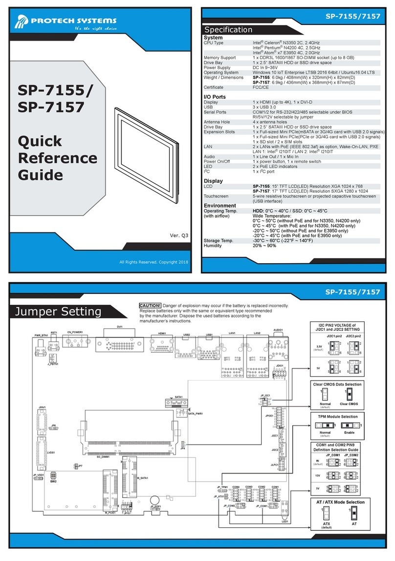
Ver. Q1
All Rights Reserved. Copyright 2019
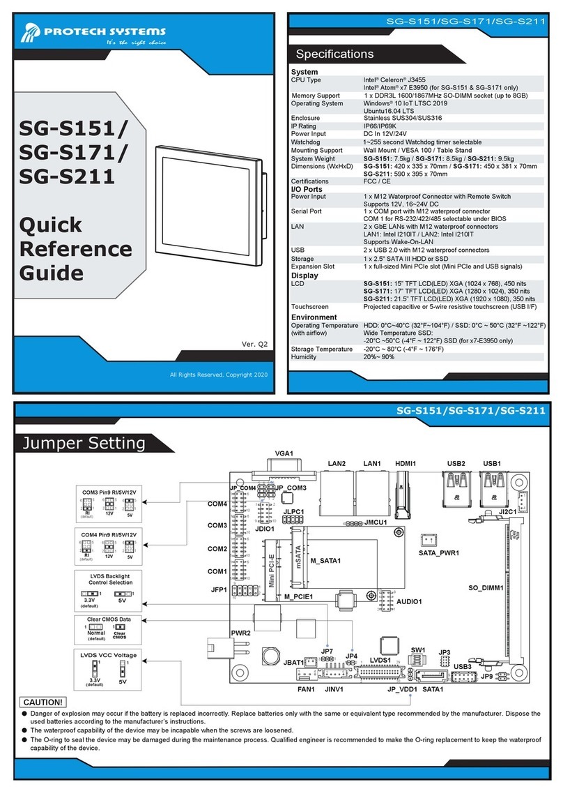
Specification
SP-S211
SP-S211
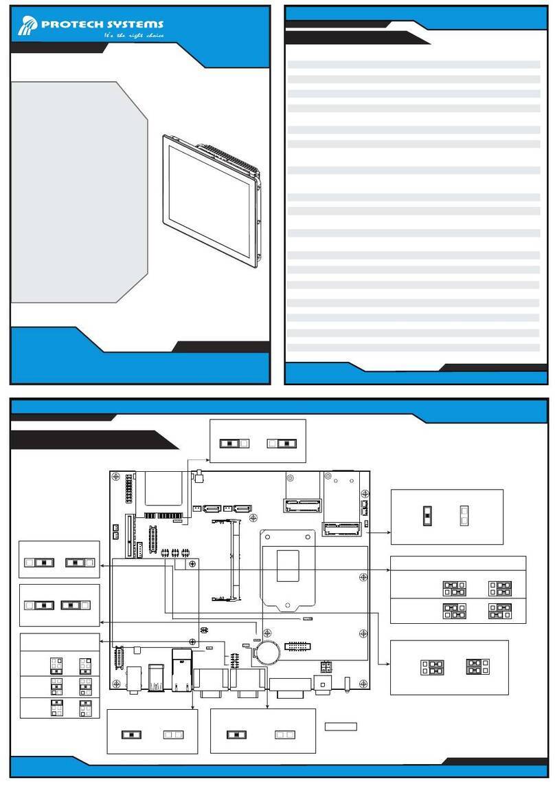
Jumper Setting
SP-S211
Quick
Reference
Guide
System
CPU Type Intel®Celeron®J3455 4C, 2.3GHz
Memory Support 1 x DDR3L 1600/1867 SO-DIMM socket (up to 8 GB)
Drive Bay 1 x 2.5” SATAIII HDD or SSD drive space
Front Bezel Stainless steel (SUS 304)
IP65 Yes (for front panel only)
Power Supply DC In 9~36V
Operating System Windows 10 loT Ent. 2019 LTSC/LTSB 2016 64bit/Ubuntu16.04 LTS
System Weight 10kg
Dimensions (WxHxD) 585 x 377 x 91.6mm
Mounting Support Wall Mount / VESA 100 / Panel Mount
Watchdog 1~255 seconds watchdog timer selectable
Certifications FCC/CE
I/O Ports
Display 1 x HDMI (up to 4K), 1 x DVI-D
USB 3 x USB 3.0
Serial Ports COM1/2 for RS-232/422/485 selectable under BIOS
RI/5V/12V selectable by jumper
Antenna Holes 4 x antenna holes
Drive Bay 1 x 2.5” SATAIII HDD or SSD drive space
Expansion Slots 1 x full-sized Mini PCIe(mSATA or 3G/4G card with USB 2.0 signals)
1 x full-sized Mini PCIe(PCIe or 3G/4G card with USB 2.0 signals)
1 x SD slot / 2 x SIM slots
LAN 2 x LANs with PoE (IEEE 802.3af) as option, Wake-On-LAN, PXE
LAN 1: Intel®I210IT / LAN 2: Intel®I210IT
Audio 1 x Line Out / 1 x Mic In
Power On/Off 1 x power button, 1 x remote switch
LED 2 x PoE LED indicators
I2C 1 x I2C port
Display
LCD 21.5” True Flat TFT LCD(LED) resolution FHD (16:9) 1920x1080
Touchscreen Projected capacitive touchscreen (USB interface)
Environment
Operating Temp. HDD: 0°C ~ 40°C(32°F~104°F)
(with airflow) SSD: 0°C ~ 45°C (32°F~122°F)
Storage Temp. -20°C ~ 80°C (-4°F ~ 176°F)
Humidity 20% ~ 90%
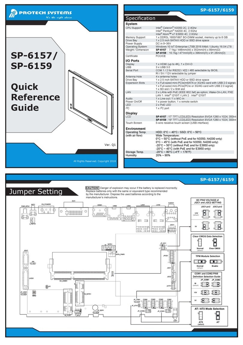
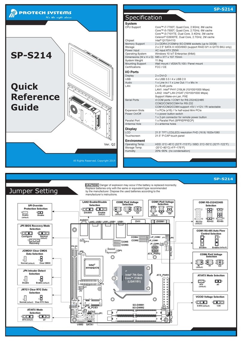
CAUTION! Danger of explosion may occur if the battery is replaced incorrectly.
Replace batteries only with the same or equivalent type recommended
by the manufacturer. Dispose the used batteries according to the
manufacturer’s instructions.
COM1 and COM2 PIN9
Definition Selection Guide
JP_COM2JP_COM1
RI
12V
5V
51
6 2
2
(default)
1
2
5
6
1
2
5
6
51
6 2
2
1
2
5
6
1
2
5
6
Clear CMOS Data Selection
Normal Clear CMOS
(default)
11
TPM Module Selection
Normal Enable
(default)
11
I2C PIN2 VOLTAGE of
JI2C1 and JI2C2 SETTING
5
1
6
2
5
1
6
2
5
1
6
2
JI2C2 pin2JI2C1 pin2
3.3V
5V
(default)
5
1
6
2
AT / ATX Mode Selection
ATX AT
(default)
11
JP_VDD1
31
JP7
1
2
LVDS1
20 19
12
JINV1
1
3
JP6
PWR_BTN1
RST1 CN_POWER1
DVI1
HDMI1 USB2 USB1 LAN1 LAN2
AUDIO1
JDIO1
JP_I2C1
JPOE1
JI2C1
JI2C2
JLPC1
COM4 COM1
COM2COM3
LED1
JP_COM1
JP_COM2
JP_ATX1
JP_TPM1
JP10
SO_DIMM1
M_SATA1
M_PCIE1
JP4
SATA_PWR1
SATA1
1
2
16
18
52 51
17
15
16
18
52
2
1
17
15
51 1
3
1
2
1
2
5
6
666
1161 1
10 510 10 10
5 5 5
1
6
5
2
2
1
3 4
1
1
1
1
9
1
2
7
8
10
4
4
2
2
1516
12
5 6
1
2
9
10
1
2 3 54
25
22
R16
R14
R16
R14
R15
R13
R15
R13
R1
R7
R6
R12 R1
R7
R6
R12
L1 L2 L3 L4 L2 L3L1 L4
A1
A9
B1
B9
A4
A5
B4
B5
1
9
4
5
119
1
9
17
8
16
24
1
2
3
3
1
1
2
2
4
4
J_PBTN1
1
2
1
272
71
74
73
204
203
1
2
1
2
1
3
JP_EDP1
SW2
30 29
2 1
17
(Unit: mm)
The following messages are reminders for safety on how to protect your system from damages and extend the life cycle.
1. Check the Cable Voltage
• The range of operating voltage should be DC 9~36V. Otherwise, the system could be damaged.
2. Environmental Conditions
• Place your SP-S211 on a sturdy, level surface. Be sure to allow enough space to have easy access around the device.
• Avoid extremely hot or cold place to install SP-S211.
• Avoid exposure to sunlight for a long period of time or in an airtight space.
• Avoid the device from any heating device or using SP-S211 when it’s been left outdoors in a cold winter day.
• Avoid moving SP-S211 rapidly from a hot place to a cold place and vice versa because condensation may come from
inside of the device.
• Don’t place SP-S211 close to any radio-active device in case of signal interference.
3. Handling
• Avoid putting heavy objects on top of the device.
• If water or other liquid spills into this product, unplug the power cord immediately.
4. Good Care
• When the outside of the case is stained, remove the stain with a neutral washing agent with a dry cloth.
• Never use strong agents such as benzene and thinner to clean the device.
• If heavy stains are present, moisten a cloth with diluted neutral washing agent or with alcohol and then wipe thoroughly with a dry cloth.
• If dust has been accumulated on the outside, remove it by using a special vacuum cleaner for computers.
CAUTION! Danger of explosion if battery is incorrectly replaced. Replace only with the same or equivalent type recommended by the
manufacturer. Dispose of used batteries according to the manufacturer’s instructions.
WARNING! Some internal parts of the system may have high electrical voltage. And therefore we strongly recommend that qualified engineers
can open and disassemble the device. Please handle LCD and Touchscreen with extra care as they are easily breakable.
Safety Precaution
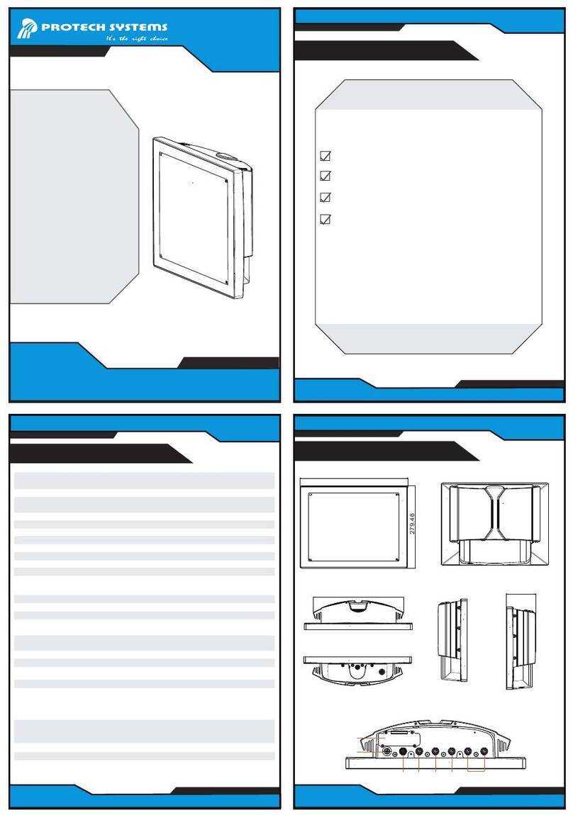
SP-S211 Overview
Installing Hooks
Step 1. Install 12 hooks into the mounting holes on
the four sides of the system using 12 x screws (M3x5mm).
Step 3. Install 12 mounting brackets onto the hooks on the four sides
of Panel PC and fasten the mating screws to secure firmly.
Step 2. Mount the system equipped with 12 hooks onto the
wall firmly.
Front View Rear View
Side View
Side View
Wall Mount Cut-Out
Quick Setup
SP-S211 Overview
(Normal Type)
(Sunlight Readable Type)
Front View Rear View
585
377
4-R2
100(VESA)
C.L.100(VESA)
138
Rear I/O View
549.20
532
184
368
341.20
324
171.20
Ø
20- 3.50
4-R3
LAN1
USB
Connector
DC-IN
9~36V
VCCGND
COM2
RESET
DC IN 9-36V DVI-D
I2C
HDMI
COM1
Remote SW
1 2
LAN1 LAN2
PoE ON
DVI-D
HDMI
LAN2
Power
Button
COM Connector Line Out
Mic In
COM
Connector
Remote
Switch
I
2
C
Reset
585
377
4-R2
28.60
91.60
44.60
14.80
319.80
89.60104.60
28.60
91.60
44.60
14.80
319.80
89.60104.60
C.L.100(VESA)
100(VESA) 138
HDD Easy Maintenance
Pull out HDD tray.
Step 1.
mark should
Heed the
be directed upwards when
you push back HDD tray.
Release the four screws
of HDD tray.
Step 3.
Release the two
screws of HDD tray.
Step 2.
Installing Memory Heatsink
Step 2. Put the click on to secure.
Step 1. Attach the adhesive tapes on both sides of the
memory module.
Memory module
Adhesive tape
click
Installing VESA Mount
Installing Panel Mount
Tighten the screws into the 20 mounting holes of the wall
fixture as shown, and then secure the panel PC onto the wall
firmly.
Wall
Install the hooks onto the
four sides of the Panel PC.
Wall
1. Install the bracket.
2. Tighten the screw.
HDD & Memory & VESA Mount
Accessories
Memory Heatsink x 2
HDD Tray
Screw
M3 x 5 mm Screw x 4
Memory Heatsink VESA Mount
VESA Mount Kit x 1
Wall
Top View
527.80
217.50
Bottom View
Top View
Bottom View
527.80
217.50
LAN2 LAN1 HDMI
12
PoEON
COM1
Remote SW
DVI-D
I2C
GND
VCC
DC IN 9-36V
COM2
RESET

Other Protech Systems Touch Panel manuals

Protech Systems PPC-1208F User manual

Protech Systems

Protech Systems PPC-1208F User manual

Protech Systems SP-7155 User manual

Protech Systems

Protech Systems SP-7155 User manual

Protech Systems SP-6265 User manual

Protech Systems

Protech Systems SP-6265 User manual

Protech Systems SP-6140 User manual

Protech Systems

Protech Systems SP-6140 User manual

Protech Systems SP-6130 User manual

Protech Systems

Protech Systems SP-6130 User manual

Protech Systems SP-6565 User manual

Protech Systems

Protech Systems SP-6565 User manual

Protech Systems SP-7117 User manual

Protech Systems

Protech Systems SP-7117 User manual

Protech Systems SP-6267 User manual

Protech Systems

Protech Systems SP-6267 User manual

Protech Systems SP-6157 User manual

Protech Systems

Protech Systems SP-6157 User manual

Protech Systems SG-S156 User manual

Protech Systems

Protech Systems SG-S156 User manual

Protech Systems SP-7165 User manual

Protech Systems

Protech Systems SP-7165 User manual

Protech Systems SG-S151 User manual

Protech Systems

Protech Systems SG-S151 User manual

Protech Systems PPC-7400 User manual

Protech Systems

Protech Systems PPC-7400 User manual

Protech Systems SP-6558 User manual

Protech Systems

Protech Systems SP-6558 User manual

Protech Systems PPC-7528F User manual

Protech Systems

Protech Systems PPC-7528F User manual

Protech Systems SP-6110 User manual

Protech Systems

Protech Systems SP-6110 User manual

Protech Systems PPC-7365F User manual

Protech Systems

Protech Systems PPC-7365F User manual

Protech Systems SP-6205 User manual

Protech Systems

Protech Systems SP-6205 User manual

Protech Systems SG-G151 User manual

Protech Systems

Protech Systems SG-G151 User manual

Protech Systems SP-7755 User manual

Protech Systems

Protech Systems SP-7755 User manual

Protech Systems SP-7256 User manual

Protech Systems

Protech Systems SP-7256 User manual

Protech Systems SP-6555 User manual

Protech Systems

Protech Systems SP-6555 User manual

Protech Systems SP-S214 User manual

Protech Systems

Protech Systems SP-S214 User manual

Popular Touch Panel manuals by other brands

Pro-face GP3000 Series Maintenance and troubleshooting

Pro-face

Pro-face GP3000 Series Maintenance and troubleshooting

Contec PT-E831H user manual

Contec

Contec PT-E831H user manual

protech prox SP-S154 Quick reference guide

protech

protech prox SP-S154 Quick reference guide

Heal-Tech GIpro X-type G2 user guide

Heal-Tech

Heal-Tech GIpro X-type G2 user guide

PowerAcoustik PDN-721HB owner's manual

PowerAcoustik

PowerAcoustik PDN-721HB owner's manual

Pro-face SP5000 Series installation guide

Pro-face

Pro-face SP5000 Series installation guide

red lion APLR Series manual

red lion

red lion APLR Series manual

Paradox TM40 Quick user guide

Paradox

Paradox TM40 Quick user guide

Contro l4 C4-TSWM10-E-W installation guide

Contro l4

Contro l4 C4-TSWM10-E-W installation guide

Pro-face GP577R-SC11 Replacement guide

Pro-face

Pro-face GP577R-SC11 Replacement guide

Contec IPC-PT/MV10 Series Software manual

Contec

Contec IPC-PT/MV10 Series Software manual

Pro-face PS-3600G Series user manual

Pro-face

Pro-face PS-3600G Series user manual

Pro-face GP-377RT Replacement  guidebook

Pro-face

Pro-face GP-377RT Replacement guidebook

Pro-face PS-3600G Series installation guide

Pro-face

Pro-face PS-3600G Series installation guide

Cal-Royal PL2S-2 user guide

Cal-Royal

Cal-Royal PL2S-2 user guide

Pro-face GP377-LG Series Replacement guide

Pro-face

Pro-face GP377-LG Series Replacement guide

protech PPC-7615 user manual

protech

protech PPC-7615 user manual

Yamatake DIGITRONIK SDC40A user manual

Yamatake

Yamatake DIGITRONIK SDC40A user manual

manuals.online logo
manuals.online logoBrands
  • About & Mission
  • Contact us
  • Privacy Policy
  • Terms and Conditions

Copyright 2025 Manuals.Online. All Rights Reserved.