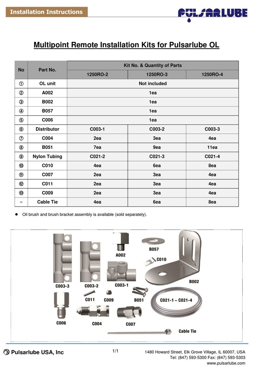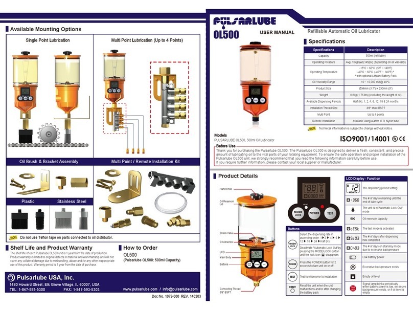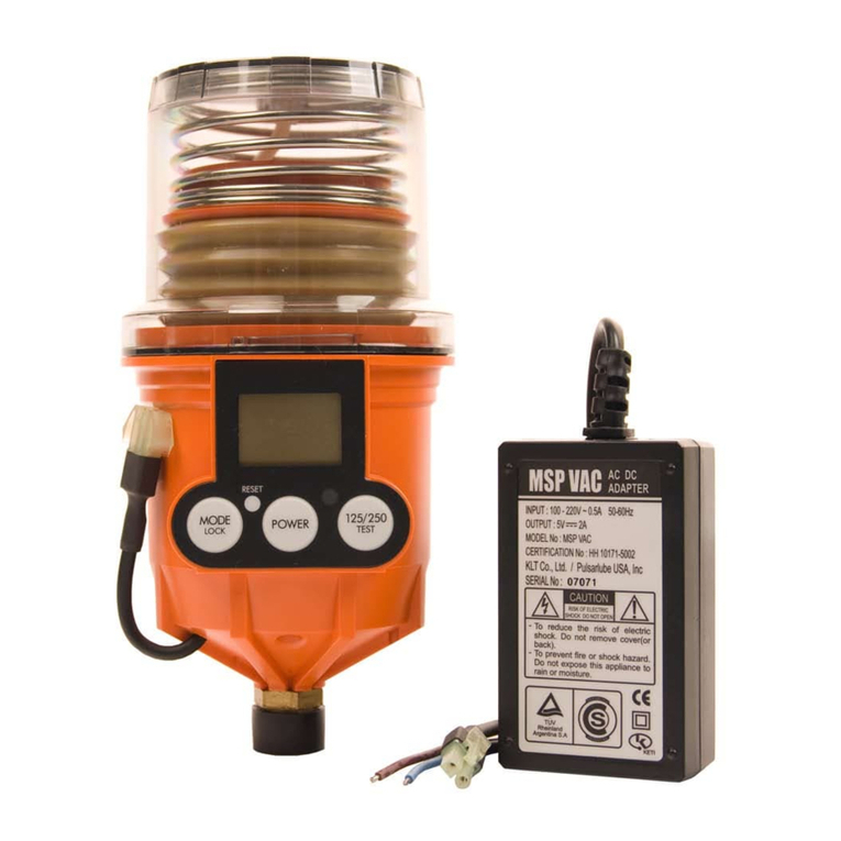
Kit No. 1250RO-2 ~1250RO-4
Warning
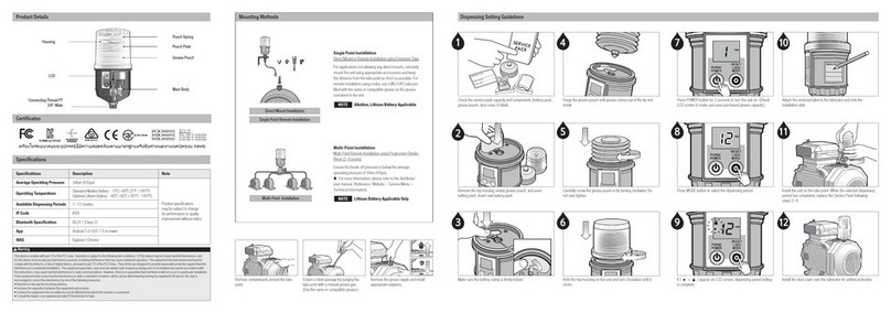
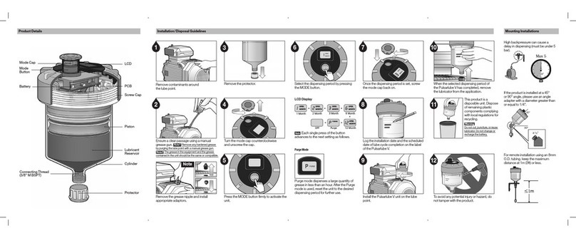
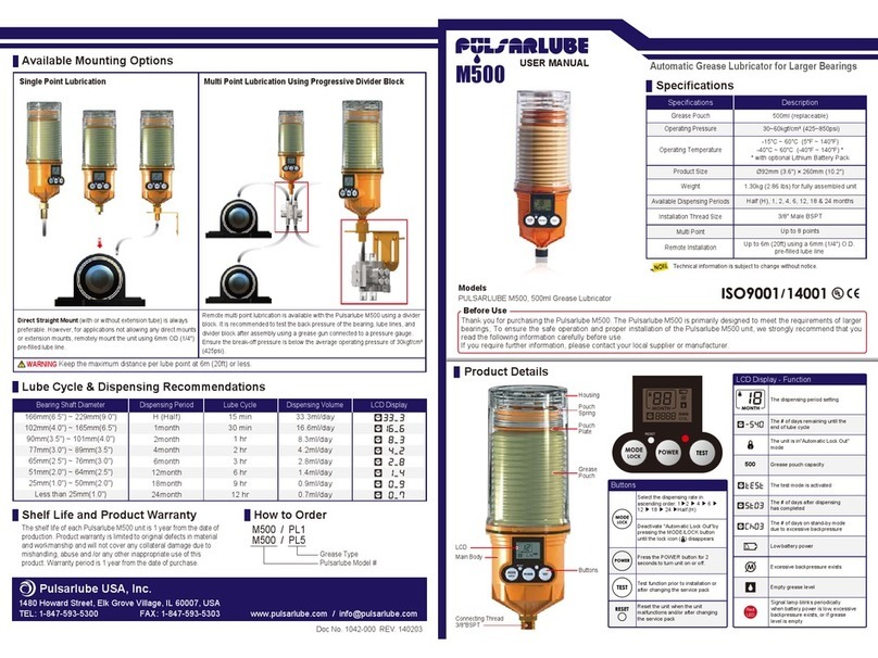
For oils below ISO VG 100, place the oilers below the lube points
and twist the lube lines a couple of times to avoid oil leaks caused
by gravity.
For oils below ISO VG 100 – OL500 products should be installed
below the lube points.
INSTALLATION INSTRUCTION
DETAILED PARTS AND ASSEMBLY PROCEDURE
www.pulsarlube.com
Multipoint Remote Installation Kit for Pulsarlube OL
Rev.00
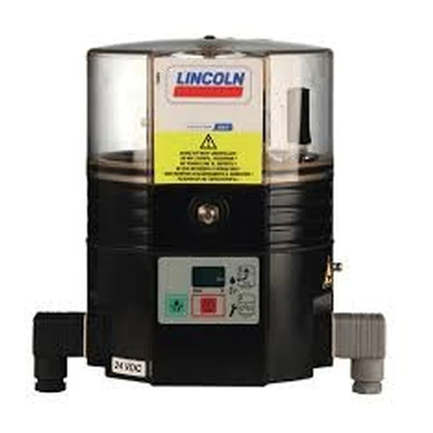
OL500 Unit
B057
C006
C003-1
C003-2
A002
B002
C021-2 C021-3
B051
C003-3
C009
C004
C004
C004
Reducer, PT 1/8"F X M8 X 1P
Distributor, 3(1P) M8 x 1P
Distributor, 4(2P) M8 x 1P
C010
Tube Clamp,
Dia. 4mm x 1R
Distributor, 5(3P) M8 x 1P
Resistance Valve, #1 Distributor Spray
C007
Tube Fitting,
Dia. 4mm x PT1/8"M
Washer
Pulsarlube OL500
Reducer, 3/8"F X 1/8"M Adaptor
Mounting Bracket, "L"Shape
Distribution Tubing,
O.D. 4mm x I.D. 2.5mm
Nylon Tubing 20ft (6m)
Ø4 X Ø2.5 Insert
Sleeve Ring, Dia. 4mm
Distribution Tubing,
O.D. 4mm x I.D. 2.5mm
Nylon Tubing 30ft (9m)
C021-4
Distribution Tubing,
O.D. 4mm x I.D. 2.5mm
Nylon Tubing 40ft (12m)
Self Drilling Screw, #8 X 20
11
11
C011
12
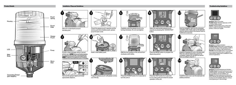
ASSEMBLY PROCEDURE
1. Install the mounting bracket ( ) at a proper location using
screws ( ) to allow for easy installation and filling of oil.
Apply PTFE Tape around the thread on fittings ( ) and ( )
and on the tip of the lubricator.
Do not use PTFE Tape on parts ( ) , ( ) , or ( ) .
Output volume may vary depending on oil viscosity, length of
lube line, ambient temperature, etc.
2. Install the lubricator using the reducer ( ), washer ( ),
and reducer ( ).
3. Remove the oil reservoir lid and fill the cartridge with oil to
the 500ml level on the label. Turn the hand knob counter
clockwise 1~2 turns before closing the lid to open the vent
and relieve vacuum pressure.
4. Press the “TEST” button for 2 seconds to run test mode.
Confirm that the unit is dispensing oil properly.
5. Assemble the reducer ( ) and the fitting connector ( ).
6. Connect one end of the tubing to the resistance valve ( )
and the other end of the tubing to the fitting connector ( ).
Assemble the insert ( ) and sleeve ring ( ) in order, as
shown in the circled image on the left.
( If an oil brush and bracket assembly is to be used, connect
brush to a fitting connector ( ) at the end of lube line using
an appropriate socket. )
7. Use the tube clamps ( ) and screws ( ) to affix the tubing
( ) to a wall.
8. Install lubricator and follow lubricator operation insturctions
on user manual.
COMMENTS
ox
NOTE : All parts above are Metric thread.
