REMS Ax-Press 25 22 V ACC User manual

AXIAL
PRESSES
INSTRUCTION MANUAL
REMS Ax-Press 25 22 V ACC
REMS Ax-Press 25 L 22 V ACC
REMS Ax-Press 30 22 V
REMS Ex-Press 22 V ACC
REMS Power-Ex-Press P-CEF ACC

2
Fig.
4
Fig.
3
Fig.
1
6123
4
9
7
8
13
13
2
2
4
4
12
12
10
10
3
3
1
1
611
9
7
8
5
Fig.
2
13
2
4
12
10
3
1
5
2

3
Fig.
5
Li-Ion
Li-Ion Plus
Li-Ion 22 V
NiMH
220 – 240 V, 12,0 V, 25A
220 – 240 V, 14,4 V, 33A
100 –120 V, 14,4 V, 18A
220 – 240 V, 21,6 V, 15A
220 – 240 V, 21,6 V, 40A
10,8 V, 1,5Ah
14,4 V, 1,5Ah
14,4 V, 3,0Ah
18,0 V, 3,0Ah
21,6 V, 1,5Ah
21,6 V, 2,5Ah
21,6 V, 5,0Ah
21,6 V, 9,0Ah
12,0 V, 2,0Ah
18,0 V, 2,0Ah
Typ Akku-Werkzeug
844510
571545
571555
565225
571570
571571
571581
571583
571510
565210
571535
571565
571565
571567
571578
560007
Akku-Cat ANC VE
18,0 V
●
560009
Akku-Cat ANC VE
18,0 V
●
580001
Akku-Curvo
18,0 V
●
580002
Akku-Curvo
18,0 V
●
575003
Akku-Ex-Press Cu
12,0 V
●
●
575002
Akku-Ex-Press Mini Q&E
12,0 V
●
●
575004
Akku-Ex-Press Q&E
14,4 V
●
●
●
575001
Akku-Ex-Press Q&E
12,0 V
●
●
575005
Akku-Ex-Press Q&E ACC
14,4 V
●
●
●
●
575006
Akku-Ex-Press Cu ACC
14,4 V
●
●
●
●
575008
Akku-Ex-Press P ACC
14,4 V
●
●
●
●
175200
Akku-LED-Lampe
14,4 V
●
●
●
●
571000
Akku-Press
12,0 V
●
●
571003
Akku-Press 14 V
14,4 V
●
●
●
576000
Akku-Press 22 V ACC
21,6 V
●
●
●
●
●
576003 Akku-Press 22 V ACC Connected 21,6 V ●●●● ●
571001
Akku-Press ACC
12,0 V
●
●
571004
Akku-Press 14 V ACC
14,4 V
●
●
●
579001
Akku-Press XL 45 kN 22 V ACC
21,6 V
●
●
●
●
530004
Amigo 22 V
21,6 V
●
●
573002
Ax-Press 15
14,4 V
●
●
●
573001
Ax-Press 15
12,0 V
●
●
573020
Ax-Press 25 22 V ACC
21,6 V
●
●
●
●
●
●
573003
Ax-Press 25 ACC
14,4 V
●
●
●
●
573021
Ax-Press 25 L 22 V ACC
21,6 V
●
●
●
●
●
●
573004
Ax-Press 25 L ACC
14,4 V
●
●
●
●
573008
Ax-Press 30 22 V
21,6 V
●
●
●
●
●
●
573005
Ax-Press 40
12,0 V
●
●
573006
Ax-Press 40
14,4 V
●
●
●
560010
Cat 22 V VE
21,6 V
●
●
●
845007
Cento 22 V
21,6 V
●
●
●
347005
Collum 22 V
21,6 V
●
●
580004
Curvo 22 V
21,6 V
●
●
●
575010
Ex-Press 22 V ACC
21,6 V
●
●
●
●
●
●
190000
Helix VE
14,4 V
●
●
●
●
153419
Hydro-Swing 22 V
21,6 V
●
●
●
●
●
●
175210 Lumen 2800 22 V 21,6 V ●●●●
578002
Mini-Press 22 V ACC
21,6 V
●
●
●
●
●
●
578000
Mini-Press ACC
12,0 V
●
●
578001
Mini-Press 14 V ACC
14,4 V
●
●
●
●
578003
Mini-Press S 22 V ACC
21,6 V
●
●
●
●
●
●
844001
Nano 11 V
14,4 V
●
560011
Tiger 22 V VE
21,6 V
●
●
571560
Schnellladegerät 220–240 V, 50–60 Hz, 65 W
●
●
●
●
●
●
571560
Schnellladegerät 100–120 V, 50 –60 Hz, 65 W
●
●
●
●
●
●
571575
Schnellladegerät 220 – 240 V, 50 –60 Hz, 70 W
●
●
●
●
571575
Schnellladegerät 100 –120 V, 50–60Hz, 70 W
●
●
●
●
571585
Schnellladegerät 100 – 240 V, 50 –60 Hz, 90 W
●
●
●
●
571587
Schnellladegerät 100 – 240 V, 50 –60 Hz, 290 W
●
●
●
●
333

4
eng eng
Translation of the Original Instruction Manual
The respective latest REMS sales literature applies for the use of REMS pressing
heads and REMS expanding heads for the different pipe connection systems, see
also www.rems.de → Downloads → Product Catalogues, Brochures.
If the system
manufacturer alters components of pipe connection systems or markets new ones,
their current application status must be enquired about at REMS (Fax +49 7151 17
1
Housing grip
2
Safety inching switch
3
Pistol grip
4
Reset button
5
Pressing heads
6
Expander
7
Expanding head
8
Expanding jaws
9
Expanding mandrel
10
Machine status check
11
Locking nut
12
Battery
13
Graduated charging level indicator
Fig. 1 –
4
Guidelines for use of REMS cordless tools, batteries, rapid chargers,
power supply units
Fig.
5
General power tool safety warnings
WARNING
WARNING
Read all safety warnings, instructions, illustrations and specifi cations provided
with this power tool.
Failure to follow all instructions listed below may result in
electric shock, fi re and/or serious injury.
Save all warnings and instructions for future reference.
The term “power tool” in the warnings refers to your mains-operated (corded) power
tool or battery-operated (cordless) power tool.
1) Work area safety
a) Keep work area clean and well lit.
Cluttered or dark areas invite accidents.
b) Do not operate power tools in explosive atmospheres, such as in the pres-
ence of fl ammable liquids, gases or dust.
Power tools create sparks which
may ignite the dust or fumes.
c) Keep children and bystanders away while operating a power tool.
Distrac-
tions can cause you to lose control.
2) Electrical safety
a) Power tool plugs must match the outlet. Never modify the plug in any way.
Do not use any adapter plugs with earthed (grounded) power tools.
Unmodi-
fi ed plugs and matching outlets will reduce risk of electric shock.
b) Avoid body contact with earthed or grounded surfaces, such as pipes,
radiators, ranges and refrigerators.
There is an increased risk of electric shock
if your body is earthed or grounded.
c) Do not expose power tools to rain or wet conditions.
Water entering a power
tool will increase the risk of electric shock.
d) Do not abuse the cord. Never use the cord for carrying, pulling or unplug-
ging the power tool. Keep cord away from heat, oil, sharp edges or moving
parts.
Damaged or entangled cords increase the risk of electric shock.
e) When operating a power tool outdoors, use an extension cord suitable for
outdoor use.
Use of a cord suitable for outdoor use reduces the risk of electric
shock.
f) If operating a power tool in a damp location is unavoidable, use a residual
current device (RCD) protected supply.
Use of an RCD reduces the risk of
electric shock.
3) Personal safety
a) Stay alert, watch what you are doing and use common sense when oper-
ating a power tool. Do not use a power tool while you are tired or under
the infl uence of drugs, alcohol or medication.
A moment of inattention while
operating power tools may result in serious personal injury.
b) Use personal protective equipment. Always wear eye protection.
Protec-
tive equipment such as a dust mask, non-skid safety shoes, hard hat or hearing
protection used for appropriate conditions will reduce personal injuries.
c) Prevent unintentional starting. Ensure the switch is in the off-position before
connecting to power source and/or battery pack, picking up or carrying the
tool.
Carrying power tools with your fi nger on the switch or energising power
tools that have the switch on invites accidents.
d) Remove any adjusting key or wrench before turning the power tool on.
A
wrench or a key left attached to a rotating part of the power tool may result in
personal injury.
e) Do not overreach. Keep proper footing and balance at all times.
This enables
better control of the power tool in unexpected situations.
f) Dress properly. Do not wear loose clothing or jewellery. Keep your hair and
clothing away from moving parts.
Loose clothes, jewellery or long hair can be
caught in moving parts.
g) If devices are provided for the connection of dust extraction and collec-
tion facilities, ensure these are connected and properly used.
Use of dust
collection can reduce dust-related hazards.
h) Do not let familiarity gained from frequent use of tools allow you to become
complacent and ignore tool safety principles.
A careless action can cause
severe injury within a fraction of a second.
4) Power tool use and care
a) Do not force the power tool. Use the correct power tool for your application.
The correct power tool will do the job better and safer at the rate for which it was
designed.
b) Do not use the power tool if the switch does not turn it on and off.
Any power
tool that cannot be controlled with the switch is dangerous and must be repaired.
c) Disconnect the plug from the power source and/or remove the battery pack,
if detachable, from the power tool before making any adjustments, changing
accessories, or storing power tools.
Such preventive safety measures reduce
the risk of starting the power tool accidentally.
d) Store idle power tools out of the reach of children and do not allow persons
unfamiliar with the power tool or these instructions to operate the power
tool.
Power tools are dangerous in the hands of untrained users.
e) Maintain power tools and accessories. Check for misalignment or binding
of moving parts, breakage of parts and any other condition that may affect
the power tool’s operation. If damaged, have the power tool repaired before
use.
Many accidents are caused by poorly maintained power tools.
f) Keep cutting tools sharp and clean.
Properly maintained cutting tools with
sharp cutting edges are less likely to bind and are easier to control.
g) Use the power tool, accessories and tool bits etc. in accordance with these
instructions, taking into account the working conditions and the work to be
performed.
Use of the power tool for operations different from those intended
could result in a hazardous situation.
h) Keep handles and grasping surfaces dry, clean and free from oil and grease.
Slippery handles and grasping surfaces do not allow for safe handling and control
of the tool in unexpected situations.
5) Battery tool use and care
a) Recharge only with the charger specifi ed by the manufacturer.
A charger
that is suitable for one type of battery pack may create a risk of fi re when used
with another battery pack.
b) Use power tools only with specifi cally designated battery packs.
Use of any
other battery packs may create a risk of injury and fi re.
c) When battery pack is not in use, keep it away from other metal objects, like
paper clips, coins, keys, nails, screws or other small metal objects, that
can make a connection from one terminal to another.
Shorting the battery
terminals together may cause burns or a fi re.
d) Under abusive conditions, liquid may be ejected from the battery; avoid
contact. If contact accidentally occurs, fl ush with water. If liquid contacts
eyes, additionally seek medical help.
Liquid ejected from the battery may cause
irritation or burns.
e) Do not use a battery pack or tool that is damaged or modifi ed.
Damaged or
modifi ed batteries may exhibit unpredictable behaviour resulting in fi re, explosion
or risk of injury.
f) Do not expose a battery pack or tool to fi re or excessive temperature.
Exposure to fi re or temperature above 130 °C may cause explosion.
g) Follow all charging instructions and do not charge the battery pack or
tool outside the temperature range specifi ed in the instructions.
Charging
improperly or at temperatures outside the specifi ed range may damage the battery
and increase the risk of fi re.
6) Service
a) Have your power tool serviced by a qualifi ed repair person using only
identical replacement parts.
This will ensure that the safety of the power tool
is maintained.
b) Never service damaged battery packs.
Service of battery packs should only
be performed by the manufacturer or authorized service providers.
Safety notes for cordless axial presses
and pipe expanders
WARNING
WARNING
Read all safety warnings, instructions, illustrations and specifi cations provided
with this power tool.
Failure to follow all instructions listed below may result in
electric shock, fi re and/or serious injury.
Save all warnings and instructions for future reference.
●
Do not use the power tool if it is damaged.
There is a danger of accident.
●
Hold the power tool fi rmly by the housing grip (
1
) and pistol grip (
3
) and
make sure you are standing fi rmly when working.
The power tool produces
a very high pressing force. It is safer to hold the tool with both hands. Therefore
be
very careful. Keep children and bystanders away while operating the power tool.
●
Do not reach into moving parts in the pressing area/expanding area.
There
is a risk of injury by crushing fi ngers or han
ds.
●
On
ly operate the axial press with pressing heads fully inserted.
Failure to
do so could lead to fracture and fl ying parts can cause serious injuri
es.
●
Al
ways screw expanding heads as far as they will go onto the expander.
Failure to do so could lead to fracture and fl ying parts can cause serious injuries.
●
Use only undamaged pressing heads, expanding heads. Damaged pressing
heads, expanding heads can jam or fracture and/or the press fi tting will be faulty.
Do not attempt to repair pressing heads, expanding heads. Failure to do so could
lead to fracture and fl ying parts can cause serious injuries.
●
Pull out the mains plug or remove the battery before assembly/disassembly
of pressing heads, expanding heads. There is a risk of injury.
●
Comply with the maintenance regulations for the power tool and follow the
maintenance instructions for pressing heads, expanding heads. Following
the maintenance instructions will have a positive effect on the life expectancy of
the power tool, pressing heads and expanding heads.
10

5
eng eng
●
Never let the power tool operate unattended. Switch off the power tool
during longer work breaks, pull out the mains plug/battery.
Electrical devices
can cause hazards which lead to material damage or injury when left unattend
ed.
●
Ch
eck the power cable, extension leads of the power tool and the power
supply regularly for damage.
Have these renewed by qualifi ed experts or an
authorised REMS customer service workshop in case of damage.
●
Only allow trained persons to use the power tool.
Apprentices may only use
the power tool when they are over 16, when this is necessary for their training
and when they are supervised by a trained operative.
●
Children and persons who, due to their physical, sensory or mental abilities
or lack of experience and knowledge are unable to operate the power tool
safely may not use this power tool without supervision or instruction by a
responsible person.
Otherwise there is a risk of injury due to false operation.
●
Only use approved and appropriately marked extension leads with a suffi -
cient cable cross-section.
Use extension leads up to a length of 10 m with
cable cross-section 1.5 mm², from 10 – 30 m with cable cross-section 2.5 m
m².
Sa
fety notes for batteries, rapid chargers,
power supply units
WARNING
WARNING
Read all safety warnings, instructions, illustrations and specifi cations provided
with this power tool.
Failure to heed the instructions can result in electric shock,
fi re and/or severe injuries.
Save all warnings and instructions for future reference.
See also www.rems.de → Downloads → Operating Instructions and
www.rems.de → Downloads → Safety Data Sheets → Batteries.
Explanation of symbo
ls
WARNING
WARNING Da
nger with a medium degree of risk which could result in
death or severe injury (irreversible) if not heeded.
CAUTION
CAUTION
Danger with a low degree of risk which could result in minor
injury (reversible) if not heeded.
NOTICE
Material damage, no safety note! No danger of inju
ry.
Do
not reach inside
Read the operating manual before starting
Use eye protection
Use ear protection
Electrical device complies with protection class II
Not suitable for using outdoors
Switched-mode power supply (SMPS)
Short-circuit-proof safety transformer (SCPST)
Environmental friendly disposal
CE conformity mark
1. Technical Data
Intended u
se
WARNING
WARNING
REMS cordless axial presses are intended for the purpose of making compression
sleeve connections.
REMS pipe expanders are intended for the purpose of expanding and calibrating pipes.
REMS batteries, rapid chargers, power supply units are intended for use in accord-
ance with the guidelines for use (fi g.
5
).
All othe
r uses are
not for the intended purpose and are prohibited.
1.1. Scope of Supply
REMS Power-Ex-Press P-CEF ACC:
Drive unit, operating instructions, steel ca
se
Cordless axial presses/pipe expanders: Drive unit, Li-Ion battery, rapid charger,
operating instructions, steel case
1.2. Article nu
mbe
rs
RE
MS Ax-Press 25
22 V
ACC drive unit 573020
REMS Ax-Press 25 L 22V ACC drive unit 573021
REMS Ax-Press 30 22 V drive unit 573008
REM
S E
x-Press 22 V ACC drive unit 575010
REMS Power-Ex-Press P-CEF ACC drive unit 5750
07
Ex
pander device Cu (REM
S E
x-Press 22 V ACC) 575252
Expander device P (REM
S E
x-Press 22 V ACC) 575253
Expander device P-CEF (REM
S E
x-Press 22 V ACC) 575256
Expanding device 16 – 40 mm, ½ – 1½"
(REMS Power-Ex-Press P-CEF ACC) 575100
Expanding device 50 – 63 mm, 2"
(REMS Power-Ex-Press P-CEF ACC) 5751
01
RE
MS battery Li-Ion 21.6 V, 1.5 Ah 571570
REMS battery Li-Ion 21.6 V, 2.5 Ah 571571
REMS battery Li-Ion 21.6 V, 5.0 Ah 571581
REMS battery Li-Ion 21.6 V, 9.0 Ah 5715
83
R
apid charger Li-Ion 220 – 240 V, 70 W 571575
Rapid charger Li-Ion 100 – 240 V, 90 W 571585
Rapid charger Li-Ion 100 – 240 V, 290 W 5715
87
Vo
ltage supply 220 – 240 V, instead of 21.6 V, 15A batteries 571567
Voltage supply 220 – 240 V, instead of 21.6 V, 40A batteries 5715
78
She
et steel case, REMS Ax-Press 25 22 V ACC /
Ax-Press 25 L 22V ACC 578290
Sheet steel case, REMS Ax-Press 30 22 V 573282
Sheet steel case, REM
S E
x-Press 22 V ACC 578290
Sheet steel case, REMS Power-Ex-Press P-CEF ACC 575278
REMS CleanM,
Machine cleaner
140119
Machine cleaner 140119Machine cleaner
1.3. Capac
ity
RE
MS Ax-Press 25 22 V ACC / 25 L 22V ACC
axial press for making compression sleeve joints
(sliding sleeve joints) on plastic pipes, composite pipes Ø 12 – 40 mm
See also www.rems.de
→
Products
→
Axial Presses
→
REMS pressing heads
→
Catalogue excerpt (PDF)
REMS Ax-Press 30 22 V
axial press for making compression sleeve joints
(sliding sleeve joints) with pinch sleeve on plastic pipes,
composite pipes Ø 12 – 32 mm
See also www.rems.de
→
Products
→
Axial Presses
→
REMS Ax-Press 30 22 V
→
Catalogue excerpt (PDF)
REM
S E
x-Press 22 V ACC
cordless pipe expander with Cu expander
for expanding
cordless pipe expander with Cu expander
for expanding
cordless pipe expander with Cu expander
and calibrating soft copper pipes s ≤ 1.5 mm, soft aluminium
pipes s ≤ 1.2 mm, soft precision steel pipes s ≤ 1.2 mm,
soft stainless-steel pipes s ≤ 1 mm Ø 8 – 42 mm
Ø ⅜ – 1¾"
See also www.rems.de
→
Products
→
Expanding, Necking
→
REMS Cu expanding heads
→
Catalogue excerpt (PDF)
REM
S E
x-Press 22 V AC
C
cordless pipe expander w
ith P expander
for expanding plastic pipes, composite pipes Ø 12 – 40 mm
See also www.rems.de
→
Products
→
Expanding, Necking
→
REMS P expanding heads
→
Catalogue excerpt (PDF)
REM
S E
x-Press 22 V AC
C
cordless pipe expander w
ith P-CEF expander for
expanding plastic Cold Expansions Fittings (P-CEF) Ø 16 – 40 mm
Ø ½ – 1½"
s ≤ 4.95 mm
See also www.rems.de
→
Products
→
Expanding, Necking
→
REMS P-CEF expanding heads
→
Catalogue excerpt (PDF)
11

6
eng eng
REMS Power-Ex-Press P-CEF ACC
pipe expander for expanding plastic
Cold Expansions Fittings (P-CEF) Ø 16 – 63 mm
Ø ½ – 2"
s ≤ 6,3 mm
See also www.rems.de
→
Products
→
Expanding, Necking
→
REMS Power-Ex-Press P-CEF ACC
→
Catalogue excerpt (PDF)
Operating tem
perature range
REMS cordless presses –10 °C – +60 °C (14 °F – +140 °F)
Battery –10 °C – +60 °C (14 °F – +140 °F)
Rapid charger 0 °C – +40 °C (32 °F – +
104
°F)
Voltage supply –10 °C – +45 °C (14 °F – +113 °F)
Mains operated presses –10 °C – +60 °C (14 °F – +140 °F)
Storage temperature range > 0°C (32 °F)
1.4.
Thrust force, stroke
Thrust force
(rated for
ce)
RE
MS Ax-Press 25
22 V
ACC 20 kN
REMS Ax-Press 25 L 22 V ACC 13 kN
REMS Ax-Press 30 22 V 30 kN
REM
S E
x-Press 22 V ACC 20 kN
REMS P
ower-Ex-Press P-CEF ACC 34 kN
Stro
ke
RE
MS Ax-Press 25 22 V ACC,
Ax-Press 25 L 22V ACC 41 mm
Ax-Press 30 22 V 23 mm
REM
S E
x-Press 22 V ACC 24 mm
REMS Power-Ex-Press P-CEF ACC 44 mm
1.5. Electric Dat
a
R
EMS Power-Ex-Press P-CEF ACC 230 V~; 50– 60 Hz; 450 W
110 V~; 50 – 60 Hz; 450 W
S3 20% (AB 2/10 min)
all-insulated, interference-
suppress
ed
RE
MS Ax-Press 25 22 V ACC /
21.6 V
–
---
; 1.5 Ah
REMS Ax-Press 25 L 22V ACC 21.6 V
–
---
; 2.5 Ah
REMS Ax-Press 30 22 V 21.6 V
–
---
; 5.0 Ah
REM
S E
x-Press 22 V ACC
REMS Ax-Press 25 L 22V ACC 21.6 V
REMS Ax-Press 30 22 V 21.6 V
21.6 V
–
---
; 9.0
Ah
Ra
pid charger Li-Ion Input
220 – 240
V~; 50 – 60 Hz; 70 W
Output
21.6
V
–
---
all-insulated, interference-suppressed
Input 100 – 120 V~; 50 – 60 Hz; 70 W
Output 21.6 V
–
---
all-insulated, interference-suppressed
Rapid charger Li-Ion Input 100 – 240 V~; 50 – 60 Hz; 90 W
Output 21.6 V
–
---
all-insulated, interference-suppressed
Rapid charger Li-Ion Input 100 – 240 V~; 50 – 60 Hz; 290 W
Output 21.6 V
–
---
all-insulated, interference-suppress
ed
Vo
ltage supply Input
220 – 240
V~; 50 – 60 Hz
Output 21.6 V
–
---; ≤ 15 A
–
---; ≤ 15 A
–
all-insulated, interference-suppressed
Voltage supply Input 220 – 240 V~; 50 – 60 Hz
Output 21.6 V
–
---; 40 A
–
---; 40 A
–
all-insulated, interference-suppressed
1.6. Dimen
sio
ns
RE
MS Ax-Press 25 22 V ACC 280×260×75 mm (11.0"×10.2"×3.0")
REMS Ax-Press 25 L 22V ACC 305×260×75 mm (12.0"×10.2"×3.0")
REMS Ax-Press 30 22 V 275×290×75 mm (10.8"×11.4"×3.0")
REM
S E
x-Press 22 V ACC 200×250×75 mm (7.9"×9.8"×3.0")
REMS Power-Ex-Press P-CEF
ACC 420×245×81 mm (16.5"×9.6"×3.2")
1.7. Weig
h
ts
RE
MS Ax-Press 25
22V
ACC drive unit without battery 2.6 kg (5.6 lb)
REMS Ax-Press 25 L
22V
ACC drive unit without battery 2.8 kg (6.1 lb)
REMS Ax-Press 30
22V
drive unit without battery 4.2 kg (9.3 lb)
REM
S E
x-Press
22V
ACC drive unit without battery
22V ACC drive unit without battery22V
without expander 2.0 kg (4,4 lb)
Expander Cu (REM
S E
x-Press 22 V ACC) 0.3 kg (0,7 lb)
Expander P (REM
S E
x-Press 22 V ACC) 0.3 kg (0,7 lb)
Expander P-CEF (REM
S E
x-Press 22 V ACC) 0.3 kg (0,7 lb)
REMS Power-Ex-Press P-CEF ACC drive unit 5.6 kg (12.2
lb)
RE
MS battery Li-Ion 21.6 V, 1.5 Ah 0.4 kg (0.9 lb)
REMS battery Li-Ion 21.6 V, 2.5 Ah 0.4 kg (0.9 lb)
REMS battery Li-Ion 21.6 V, 5.0 Ah 0.8 kg (1.8 lb)
REMS battery Li-Ion 21.6 V, 9.0 Ah 1.1 kg (2.4
lb)
Pr
essing heads (pair, average) 0.3 kg (0.7 lb)
REMS expander (average) 0.2 kg (0.4 lb)
REMS P-CEF expanding head (average) 0.2 kg (0.4
lb)
1.
8. Noise information
Emission at workpla
ce
RE
MS Ax-Press 25 22 V ACC /
L 22 V ACC L
pA
= 73 d
pA
= 73 d
pA
B(A)
L
WA
LWA
L
= 84 d
WA = 84 d
WA
B(A)
K = 3 d
B(A)
REMS Ax-Press 30 22 V L
pA
= 74 d
pA
= 74 d
pA
B(A)
L
WA
LWA
L
= 85 d
WA = 85 d
WA
B(A)
K = 3 d
B(A)
REM
S E
x-Press 22 V ACC
L
pA
= 73 d
pA
= 73 d
pA
B(A)
L
WA
LWA
L
= 84 d
WA = 84 d
WA
B(A)
K = 3 d
B(A)
REMS
Power-Ex-Press P-CEF ACC
L
pA
=
pA
=
pA
81 dB(A) L
WA
= 92 dB(A) K = 3
WA = 92 dB(A) K = 3 WA
d
B(A)
1.9. Vibrations
Weighted effective value of acceleration < 2,5 m/s² K = 1,5 m/s²
The specifi ed vibration emission value was measured according to a standard
test method and can be used for comparison with another power tool. The
specifi ed vibration emission value can also be used for an initial estimation of
the cut-out.
CAUTION
CAUTION
The vibration emission value may differ from the specifi ed value during actual
use of the power tool depending on the manner in which the power tool is used.
Dependent upon the actual conditions of use (periodic duty) it may be necessary
to establish safety precautions for the protection of the operator.
2. Preparations for Use
CAUTION
CAUTION
After the drive unit has been in storage for a long period of time, the overpres-
sure valve must be actuated fi rst by pressing the reset button (
4)
before putting
back into operation. If it is stuck or stiff, it may not be pressed. The drive unit
must be handed over to an authorized REMS customer service workshop for
inspection.
The respective latest REMS sales literature applies for the use of REMS pres-
sing heads and REMS expanding heads for the different pipe connection
systems, see also www.rems.de → Downloads → Product Catalogues, Brochures.
If the system manufacturer alters components of pipe connection systems or
markets new ones, their current application status must be enquired about at
REM
and error.
2.1. Electrical connection
WARNING
WARNING
Note the mains
voltage!
Before con
necting the drive unit, the rapid charg
er
or the power supply unit, check whether the voltage given on the rating plate
corresponds to the mains voltage.
On building sites, in a wet environment,
indoors and outdoors or under similar installation conditions, only operate the
power tool on the mains with a fault current protection switch (FI switch) which
interrupts the power supply as soon as the leakage curre
nt to earth excee
ds
30 mA for 200 ms.
Rechargeable batteri
es
To
tal disch
arging by undervo
ltage
The Li-Ion batteries may not drop below a minimum voltage because otherwise
the battery could be damaged by total discharge. The cells of the REMS Li-Ion
battery are delivered pre-charg
ed to approx. 40 %. Therefore the Li-Ion batteries
must be charged before use and recharged regularly. Failure to observe this
regulation of the cell manu
facturer can lead to damage to the Li-Ion battery by
total discharging.
Total discharging d
ue to storage
If a relatively low charged Li-Ion battery is stored, self discharging can lead to
total discharge damage of the batt
ery after longer storage. Li-Ion batteries must
therefore be charged before storing and recharged every six months at the
latest and charged again
before use.
NOTICE
Charge the batte
ry before use. Recharge Li-Ion batteries regularly to avoid
their total discharge. The rechargeable battery will be damaged by total
discharge.
Only use approved REMS rapid chargers for charging the REMS battery, see
Guidelines for use, fi g.
5
.
New Li-Ion batteries and Li-Ion batteries w
hich have
not b
een used for a long time only reach full capacity after several charg
es.
Rapid charger Li-Ion (Art. No. 57
1575, 571585, 571587)
The left control lamp lights up and remains green when the mains plug is
plugged in. If a b
att
ery is inserte
d in the rapid charger, the green control lamp
fl ashes to indicate that the battery is charging.
The green light stops fl ashing
and remain
s on to signal that the battery is fully charged. If the red control lamp
fl ashes, the battery is defective. If the red control lamp comes on and remains
on, this indicates that the temperature of the rapid charger and / or the battery
is outside the permi
ssible
operating range of the rapid charger of 0°C to +40°C.
NOTICE
The rapid chargers are not suit
able for outdoor u
se.
12

7
eng eng
2.2.
Installing (
changing) the pressing heads (
5
) in axial presses (Figs.
1, 2
)
Remove the battery. Only use system-specifi c pressing heads. REMS press ing
heads have a letter to
identify the compression sleeve syste
m and a number
to identify the size. Read and observe the
installation and assembly instructions
of the manufacturer/supplier of the used compression sleeve system. Never
use non-matching pressing heads (compression sleeve system, size) for
pressing work. The press joint could be unserviceable, and both the machine
and the pressing heads might be damaged.
Push the selected pressing heads (
5
) right in, if necessary turning them until
they engage (ball catch). Keep the pressing heads and locating hole inside the
pressing device clea
n.
2.
3
. Installing (c
hanging) the expanding head (
7
) in REMS Power-Ex-Press
P-CEF ACC (Fig.
4
)
Pull out the mains plug. Read and observe th
e installation and assembly
instructions of the manufacturer/supplier of the used system. Never use non-
matching expanding heads (s
ystem, size) for expansion work. The joint could
be unserviceable, and both the machine and the expanding heads might be
damaged. Grease the cone of the expanding mandrel (
9
) lightly. Screw the
selected expanding head as far as it will go onto the expander. Read and
observe the installation and assembly instructions of the manufacturer/supplier
of the used system.
REMS P and Cu expanding heads are unsuitable for the
REMS Power-Ex-Press P-CEF ACC and may therefore not be used..
Changing the expanding device on the REMS Power-Ex-Press P-CEF ACC
Pull out the mains plug. Unscrew the expanding device
(6)
from the REMS
Power-Ex-Press P-CEF ACC. Screw on the selected ex
pander as far as it will
go
and tighten by
hand.
2.
4
. Assembly (changing) of the expander
(6)
, the expanding head
(7)
on REM
S
E
x-Press 22 V ACC (Fig.
3
)
Choose an expander
(6)
to match the expanding head
(7)
. Use the expander
Cu for the REMS Cu expanding heads. Use the expander P for the REMS P
expanding heads. Use the P-CEF expander for the REMS expanding heads.
Only use system-specifi c expanding heads. REMS P and REMS P-CEFexpanding
heads are labelled with letters to identify the compression sleeve system and
a number to identify the size, REMS Cu expanding heads only with a number
to identify the size. Read and observe the installation and assembly instructions
of the manufacturer/supplier of the used system. Never expand with an unsuit-
able expander, unsuitable expanding heads (system, size). The joint could be
useless and the machine and expanding heads could be damaged.
Grease
the cone of the expanding mandrel
(9)
lightly.
Changing the P and Cu expander
Screw the s
elected expanding head onto the expanding device
(6)
to the stop.
The expanding device must now be set so t
hat the thrust of the drive machine
is taken up by the drive machine and not the expanding head at the end of the
expanding. Unscrew the expanding device
(6)
complete with screwed on
expanding head from the drive machine for this. Let the feed piston run forward
as far as possible without
the machine switching into reverse. In this position
the expander with screwed-on expanding head must be screwed onto the drive
unit until the expanding jaws
(8)
of the expanding head
(7)
are fully open. The
expanding head must be
secured with the locking nut
(11)
in this position.
NOTICE
Make sure that the compression sleeve is far enough away from the expanding
head
(7)
in the expanding process because otherwise the expanding jaws
(8)
can bend or bre
ak.
Changing the P-CEF expander
Remove the battery. Screw on the locking nut
(11)
and the selected expander
(6)
up to the stop. Screw the selected expanding head
(7)
onto the expander
up to the stop.
3. Operation
CAUTION
CAUTION
After the drive unit has been in storage for a long period of time, the overpressure
valve must be actuated fi rst by pressing the reset button (13) before putting back
into operation. If it is stuck or stiff, it may not be pressed. The drive unit must be
handed over to an authorized REMS customer service workshop for inspectio
n.
3.1. A
xial press
es (Figs.
1, 2
)
Note the different working range of the axial presses. The respectively latest
REMS sales literature applies, see also
www.rems.de
→ Downloads → Product
Catalogues, Brochures. Make sure that the pressing heads (
5
) are inserted
into the drive unit in such a way that the pressing can be made in one stroke
if possible. This is not possible in some cases and pre-pressing and fi nish
pressing is necessary. For this, one pressing head or both pressing heads must
be inserted turned 180° before the second pressing process so that they are
closer together.
Working procedure
CAUTION
CAUTION
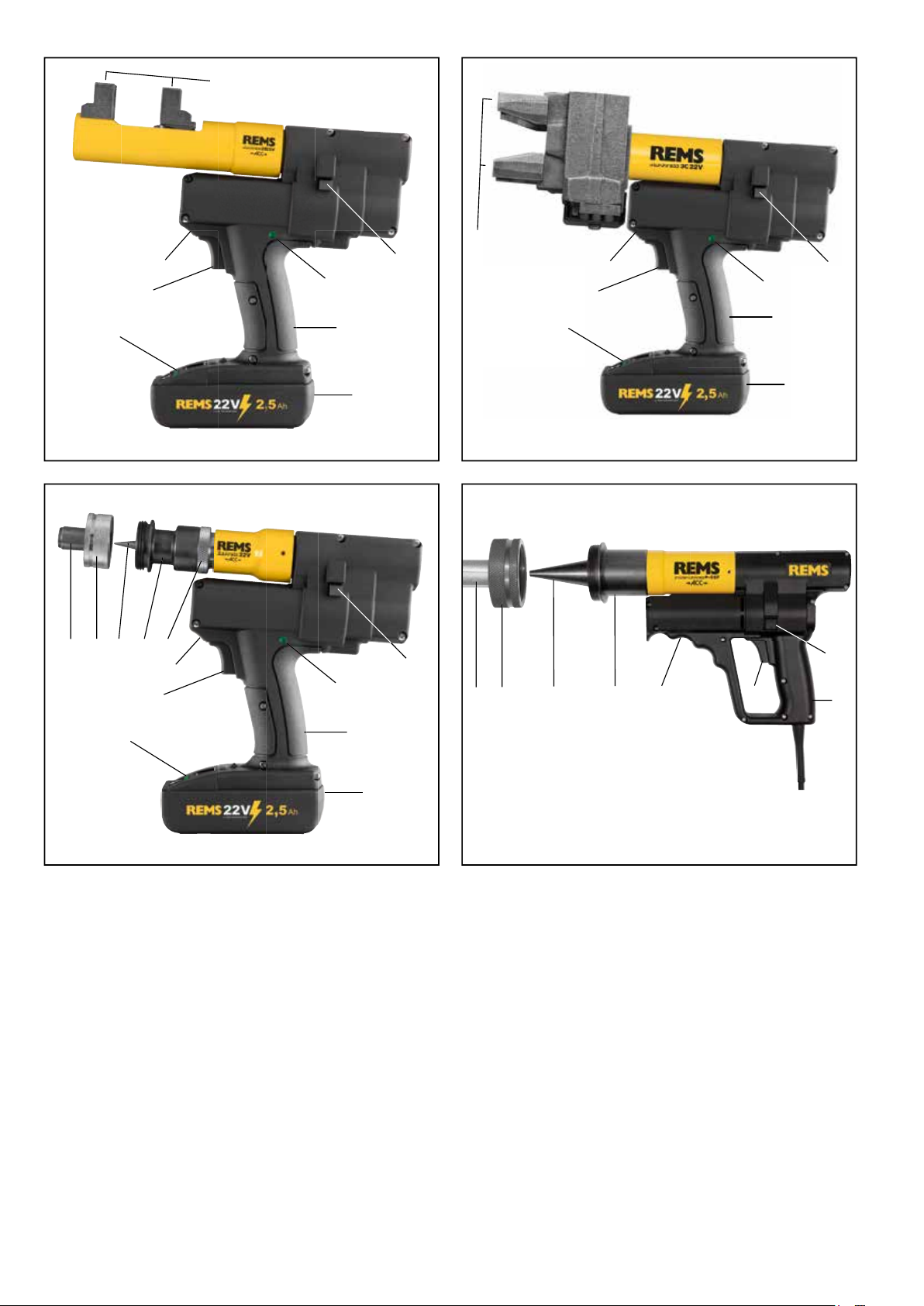
Danger of cru shing! Keep your hands away from the moving pressing
heads (5)!
In REMS Ax-Press 30 22 V (Fig. 2) , place the preassembled compression
sleeve fi tting inside the pressing heads (5). Hold the drive unit by the housing
grip (1) and the pistol grip (3), and keep the safety inching switch (2) pressed
until the compression sleeve is in contact with the collar of the compression
sleeve fi tting This is indicated by an acoustic signal (click). Hold the reset button
(4) until the pressing heads (5) have moved back completely.
In REMS Ax-Press 25 22 V ACC, REMS Ax-Press 25 L 22 V ACC (Fig. 1), place
the preassembled compression sleeve fi tting inside the pressing heads (5).
On
the REMS Ax-Press 25 L ACC the closer distance of the pressing heads may
have to be achieved by m
oving the outer pressing head into the centre pressing
head position. Hold the drive machine either with one hand on the switch handle
(3)
or two hands on the housing handle
(1)
and the switch handle
(3)
. Keep the
safety inching switch
(2)
pressed until the compression sleeve is touching the
collar of the compression sleeve connector. The drive machine then switches
automatically to return (forced return).
If there is a noticeable gap between the compression sleeve and the collar of
the compression sleeve connector after closing the compression heads, the
pressing may be faulty or leaking (see 5. Faults). Read and observe the instal-
lation and assembly instructions of the manufacturer/supplier of the pressing
sleeve system to be pressed.
With the compression sleeve system IV, various pressing heads are needed
for one pipe size. Consult and comply with the instructions for installation and
fi tting of the system’s man
ufacturer.
3.
2
. Pipe expanders
Working procedure
In REMS Ex-Press 22 V ACC with expander Cu (Fig. 3), insert the expanding
head into the pipe up to the stop and press the expanding head/drive unit
against the pipe.
Switch on the drive unit. If the expanding head is open, the
drive unit switches automatically to return and the expanding head is closed
again. Read and observe the installation and assembly instructions of the
manufacturer/supplier of the used system.
In REMS Ex-Press 22 V ACC with expander P (Fig. 3), push the compression
sleeve over the pipe, insert the expanding head into the pipe up to the stop
and press the expanding head/drive unit against the pipe.
Switch on the drive
unit. Make sure that the compression sleeve is far enough away from the
expanding head in the expanding process because otherwise the expanding
jaws
(8)
can bend or break. Keep the safety inching switch
(2)
pressed until
the pipe is expanded. This is indicated by an acoustic signal (click). Expand
several times if necessary. Turn the pipe slightly. Read and observe the instal-
lation and assembly instructions of the manufacturer/supplier of the used system.
In REMS Ex-Press 22 V ACC with expander P-CEF, REMS Power-Ex-Press
P-CEF ACC (Fig. 3, 4), p
ush a ring of the appropriate size onto the pipe. Insert
the expan
sion head into the pipe and press the expanding head/drive unit
against the pipe. Switch on the drive unit. When the expanding head is opened,
the dri
ve unit switches automatically to return and the expanding head is closed
again. Keep holding the safety inching switch
(2)
down in the REM
S E
x-Press
22 V
ACC and push the expanding head/drive unit further. Turn the pipe slig
htly.
Keep repeating the expansion process until the expanding jaws
(8)
are slid all
the way into t
he pipe.
On REMS Power-Ex-Press P-CEF ACC, release the
safety inching switch
(2)
after every expanding process, wait until the expanding
mandrel has moved back completely, turn the pipe, then press the safety inching
switch
(2)
again. Repeat the expanding process until the expanding jaws
(8)
are pushed into the pipe up to the stop. Read and observe the installation and
assembly instructions of the manufacturer/supplier of the used system.
3.3. Safety during operation
Functional safety
REMS Ax-Press 30 22 V ends the pressing operation automatically, emitting
an acoustic signal (clicking).
REMS Ax-Press 25 22 V ACC, REMS Ax-Press 25 L 22V ACC and REMS
Ex-Press 22 V ACC end the pressing operation automatically, emitting an
acoustic signal (clicking) and return automatically (automatic circuit control).
Working safety
To ensure safe working, the drive units are equipped with a safety inching switch
(2). This permits immediate switching off of the drive units at any time, particu-
larly if a potential hazard arises. The drive units can be switched to the return
function in any position.
3.4.
Machine status check with fl at battery protection
All REMS Akku presses have been equipped with an electronic machine status
check with charging level indicator (10) with a 2-coloured green/red LED since
01/01/2011.
The LED lights green when the battery is fully or still suffi ciently
charged. The LED lights red when the battery must be charged. If this condition
occurs during pressing and the pressing process is not fi nished, the pressing
must be completed with a fully charged Li-Ion battery. If the drive unit is not
used, the LED goes out after approx. 2 hours but comes on again when the
drive unit is switched back on.
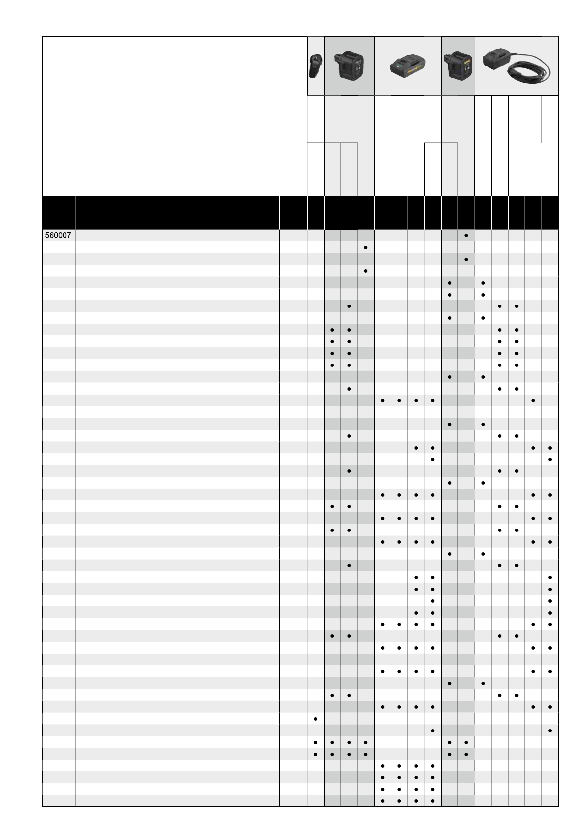
3.5. Graduated charging level indicator
(13)
of the Li-Ion 21.6 V battery
The graduated charging level indicator show
s the charging level of the battery
with 4 LEDs. At least one LED lights for a few seconds after pressing the key
with the battery symbol. The more
LEDs that light green, the higher the charging
level of the battery. If a LED fl ashes
red, the bat
tery
must be recharg
ed.
13

8
eng eng
3.6.
Power supply unit (accessory art. no.
571567, 571578
)
The power supply units are intended for mains operation of the cordless tools in
place of the battery. See the guidelines for use (Fig.
5
) for the intended use. The
power supply units are equipped with overvoltage and temperature protection.
The operating state is indicated by a LED. A lit LED indicates that the device is
ready for operation. If the LED goes out or fl ashes, this indicates an overcurrent
or impermissible temperature. The drive unit cannot be used during this time.
After a dwell time, the LED lights again and work can be continued.
NOTICE
The power supply units are not suitable for outdoor use.
4. Maintenance
Notwithstanding the servicing listed below it is recommended to send in the
REMS drive units together with all the tools (e.g. pressing heads, expanding
heads) and accessories (e.g. batteries, rapid chargers, power supply units) at
least once a year to an authorised REMS customer service station for inspec-
tion and repeated inspection of electrical equipment.
In Germany, such periodic
testing of electrical devices should be performed in accordance with DIN VDE
0701-0702 and also prescribed for mobile electrical equipment according to
the accident prevention rules DGUV, regulation 3 "Electrical Systems and
Equipment". In addition, the respective national safety provisions, rules and
regulations valid for the application site must be considered and observed.
WARNING
WARNING
Notwithstanding the servicing listed below it is recommended to send in the
REMS drive units together with all the tools (e.g. pressing tongs, pressing tongs
Mini, pressing rings with adapter tongs, a
dapter tongs Mini, compression heads,
expanding heads) and accessories (e.g. batteries, rapid chargers) at least once
a year to an authorised REMS customer service station for inspection and
repeated inspection of electrical equipment
in accordance with EN 62638:2010-08
(VDE 0702).
4.1. Servicing
WARNING
WARNING
Before
service work, pull the mains plug or remove the battery!
Keep pressing heads and expanding heads, and particularly their receptacles,
clean.
Clean heavily soiled metal parts with the REMS CleanM (Art. No. 140119)
cleaner, for example, and then protect against rust
.
Clean plastic parts (e.g. housing, batteries) only with the REMS CleanM (Art. No.
140119) or a mild soap and a damp cloth. Do not use domestic cleaning agents.
These
frequently contain chemicals that can attack plastic parts. On no account
use petrol, turpentine oil, thinners or similar products to clean plastic parts.
Make sure that liquids never get inside the power tool. Never immerse the
power tool in liquid.
Axial presses
Keep the compression heads (5) and mounting bores in the pressing device
and the pressing device itself clean.
Pipe expanders
Keep the expander (6), expanding heads (7) and expanding mandrel (9) clean.
Grease the expanding mandrel (9) lightly from time to time.
4.2. Inspection/repair
WARNING
WARNING
Before any repair work, pull the mains plug or remove the battery!
This
work may only be performed by qualifi ed personnel.
The motor of REMS Power-Ex-Press P-CEF ACC has carbon brushes. These
wear and must therefore be checked and renewed from time to time. Only use
original REMS carbon brushes. In the battery-operated drive units, the carbon
brushes of the motor are subject to wear. These cannot be replaced; the DC
motor must be replaced. The sealing rings (O-rings) wear in all electro-hydraulic
drive units. These must therefore be checked and renewed from time to time.
If the pressing power is insuffi cient or oil is lost, the drive unit must be inspected
and if necessary repaired by an authorised REMS customer service station.
NOTICE
Do not attempt to repair damaged or worn pressing heads and expanding
heads.
5. Troub
le
CAUTION
CAUTION
Af
ter the drive unit has been in storage for a long period of time, the overpressure valve must be actuated fi rst by pressing the reset button (
After the drive unit has been in storage for a long period of time, the overpressure valve must be actuated fi rst by pressing the reset button (Af
4
) before putting back
into operation. If it is stuck or stiff, it may not be pressed. The drive unit must be handed over to an authorized REMS customer service workshop for inspection.
5.1.
Fault:
Drive unit does not work.
Cause:
Remedy:
●
Worn carbon brushes.
●
Have the carbon brushes or DC motor changed by qualifi ed personnel or an
authorised REMS customer service workshop.
●
Mains lead defecti
ve (RE
MS Power-Ex-Press P-CEF ACC).
●
Have the mains lead replaced by qualifi ed personnel or an authorised REMS
customer service workshop.
●
Battery depleted or defective (REMS cordless drive units).
●
Charge the battery with the rapid charger or change the battery.
●
Drive unit defective.
●
Have the drive unit checked/repaired by an authorised REMS customer service
workshop.
5.2.
Fault:
The pipe is crushed between the press fi tting and the fi tting joint in axial pressing.
Cause:
Remedy:
●
Expansion too long.
●
Check whether the right expanding head was used. Pipe expanded several
times, observe the installation and assembly instructions of the manufacturer/
supplier of the press fi tting system to be pressed.
●
Pipe pushed too wide onto the support sleeve of the press fi tting.
●
Check whether the right expanding head was used. Pipe expanded several
times, observe the installation and assembly instructions of the manufacturer/
supplier of the press fi tting system to be pressed.
●
Wrong expanding head (press fi tting system, size) inserted.
●
Change expanding head.
●
Unsuitable matching of press fi tting, pipe and support sleeve.
●
Check the compatibility of the press fi tting, pipe and support sleeve and contact
the manufacturer/supplier of the press fi tting system to be pressed if necessary.
5.3.
Fault:
A prominent gap is left between the press fi tting and the fi tting joint after closing the pressing heads in axial pressing.
Cause:
Remedy:
●
Pipe crushed between the compression sleeve and the fi tting coll
ar
●
See fault 5.2.
●
Wrong compression head (compression sleeve system, size) used.
●
Change pressing head.
●
Battery depleted or defective (REMS cordless drive units).
●
Charge the battery with the rapid charger or change the battery.
●
Drive unit defective.
●
Have the drive unit checked/repaired by an authorised REMS customer service
workshop.
14

9
6. Disposal
The drive units, batteries, rapid chargers and power supply units may not be
thrown in the household waste at the e
nd of their useful lives.
They must be
disposed of properly by law.
Lithium batteries and battery packs of
all battery
systems may only be disposed of in the discharged state, all contacts of incom-
pletely discharged lithium batteries and battery packs mus
t be covered
with
insulating tape.
7. Manufacturer’s Warranty
The warranty period shall be 12 mon
ths from delivery of the new product to the
fi rst user. The date of delivery shall be documented by the submission of the
original purchase documents, which must include the date of purchase and the
designation of the product. All functional defects occurring within the warranty
period, which are clearly the consequence of defects in production or materials,
will be remedied free of charge. The remedy of defects shall not extend or
renew the warranty period for the product. Damage attributable to natural wear
and tear, incorrect treatment or misuse, failure to observe the operational
instructions, unsuitable operating materials, excessive demand, use for unau-
thorized purposes, interventions by the customer or a third party or other
reasons, for which REMS is not responsible, shall be excluded from the warranty.
Services under the warranty may only be provided by customer service stations
authorized for this purpose by REMS. Complaints will only be accepted if the
product is returned to a customer service station authorized by REMS without
prior interference and in a fully assembled condition. Replaced products and
parts shall become the property of REMS.
The user shall be responsible for the cost of shipping and returning the product.
A list of the REMS-authorized customer service stations is available on the
Internet under www.rems.de. For countries which are not listed, the product
must be sent to the SERVICE-CENTER, Neue Rommelshauser Strasse 4,
71332 Waiblingen, Deutschland. The legal rights of the user, in particular the
right to make claims against the seller in case of defects as well as claims due
to wilful violation of obligations and claims under the product liability law are
not restricted by this warranty.
This warranty is subject to German law with the exclusion of the confl ict of laws
rules of German International Private Law as well as with the exclusion of the
United Nations Convention on Contracts for the International Sales of Goods
(CISG). Warrantor of this world-wide valid manufacturer’s warranty is REMS
GmbH & Co KG, Stuttgarter Str. 83, 71332 Waiblingen, Deutschland.
8. Extension of the manufacturer’s guarantee to 5 years
For the drive units listed in these operating instructions it is possible to extend
the guarantee time of the above manufacturer guarantee to 5 years by registering
the drive unit under www.rems.de/service within 30 days of handover to the
fi rst user. Claims from the extension of the manufacturer guarantee can only
be made by the registered fi rst users on condition that the rating plate on the
drive unit is not removed or changed and the data are legible. Cession of the
claims is excluded.
9. Spare parts lists
For spare parts lists, see
www.rems.de
→ Downloads → Parts lists.
eng eng
5.4.
Fault:
Expander does not complete the expanding, expanding head does not open fully.
Cause:
Remedy:
●
Drive unit overheated (REMS Power-Ex-Press P-CEF ACC).
●
Let the drive unit cool down for about 10 minutes.
●
Worn carbon brushes.
●
Have the carbon brushes or DC motor changed by qualifi ed personnel or an
authorised REMS customer service workshop.
●
Battery depleted or defective (REMS cordless drive units).
●
Charge the battery with the rapid charger or change the battery.
●
Drive unit defective.
●
Have the drive unit checked/repaired by an authorised REMS customer service
workshop.
●
Wrong expanding head (press fi tting system, size) inserted.
●
Change expanding head.
●
Expanding head stiff or defective.
●
Do not use the expanding head anymore! Clean the expanding head and
grease lightly with machine oil or change.
●
Expander set incorrectly (REMS Ex-Press Cu 22 V ACC,
REMS Ex-Press P 22V ACC).
●
Reset the expander, see
2.4.
●
Distance from the press fi tting to the expanding head too small.
●
Increase the distance between the press fi tting and the expanding head.
15
Other manuals for Ax-Press 25 22 V ACC
1
This manual suits for next models
4
Table of contents
Other REMS Tools manuals

REMS
REMS Amigo User manual

REMS
REMS Ax-Press 25 22 V ACC User manual

REMS
REMS Curvo User manual

REMS
REMS Swing User manual

REMS
REMS Magnum 2000 RG-T User manual

REMS
REMS Eskimo User manual

REMS
REMS Eco-Press User manual

REMS
REMS Mini Cobra User manual

REMS
REMS Akku-Press 22 V ACC Connected User manual

REMS
REMS Hot Dog 2 User manual