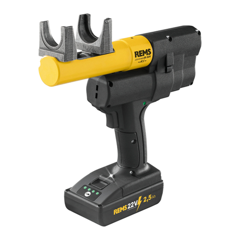
REMS Ax-Press 25 22 V ACC User manual

R
EMS Ax-Press 25 22V ACC
REMS Ax-Press 25 L 22V ACC
REMS Ax-Press 30
22V
REM
S E
x-Press 22V ACC
REMS Power-Ex-Press P-CEF ACC
REMS GmbH & Co KG
Maschinen- und Werkzeugfabrik
Stuttgarter Straße 83
71332 Waiblingen
Deutschland
Telefon +49 7151 1707-0
Telefax +49 7151 1707-110
www.rems.de
for Professionals
deu Betriebsanleitung
..............................................
4
eng Instruction Manual
...........................................
10
fra Notice d’utilisation
...........................................
16
ita Istruzioni d’uso
.................................................
22
spa Instrucciones de servicio
................................
28
nld Handleiding
.......................................................
34
swe Bruksanvisning
................................................
40
nno Bruksanvisning
................................................
46
dan Brugsanvisning
................................................
52
fi n Käyttöohje
.........................................................
58
por Manual de instruções
.......................................
64
pol Instrukcja obsługi
.............................................
71
ces Návod k použití
.................................................
78
slk Návod na obsluhu
............................................
84
hun Kezelési utasítás
..............................................
90
hrv Upute za rad
......................................................
96
srp Uputstvo za rad
..............................................
102
slv Navodilo za uporabo
......................................
108
ron Manual de utilizare
.........................................
114
rus Руководство по эксплуатации
...................
120
ell Οδηγίες χρήσης
..............................................
127
tur Kullanım kılavuzu
...........................................
134
bul Ръководство за експлоатация
...................
140
lit Naudojimo instrukcija
....................................
147
lav Lietošanas instrukcija
....................................
153
est Kasutusjuhend
...............................................
159

Fig.
4
Fig.
3
Fig.
1
6123
4
9
7
8
13
13
2
2
4
4
12
12
10
10
3
3
1
1
611
9
7
8
5
Fig.
2
13
2
4
12
10
3
1
5
2

Fig.
5
Li-Ion
Li-Ion Plus
Li-Ion 22V
NiMH
220–240V, 12,0V, 25A
220–240V, 14,4V, 33A
100–120V, 14,4 V, 18A
220–240V, 21,6V, 15A
220–240V, 21,6V, 40A
10,8V, 1,5Ah
14,4V, 1,5Ah
14,4V, 3,0Ah
18,0V, 3,0Ah
21,6V, 1,5Ah
21,6V, 2,5Ah
21,6V, 5,0Ah
21,6V, 9,0Ah
12,0V, 2,0Ah
18,0V, 2,0Ah
Typ Akku-Werkzeug
844510
571545
571555
565225
571570
571571
571581
571583
571510
565210
571535
571565
571565
571567
571578
560007
Akku-Cat ANC VE
18,0V
●
560009
Akku-Cat ANC VE
18,0V
●
580001
Akku-Curvo
18,0V
●
580002
Akku-Curvo
18,0V
●
575003
Akku-Ex-Press Cu
12,0V
●
●
575002
Akku-Ex-Press Mini Q&E
12,0V
●
●
575004
Akku-Ex-Press Q&E
14,4V
●
●
●
575001
Akku-Ex-Press Q&E
12,0V
●
●
575005
Akku-Ex-Press Q&E ACC
14,4V
●
●
●
●
575006
Akku-Ex-Press Cu ACC
14,4V
●
●
●
●
575008
Akku-Ex-Press P ACC
14,4V
●
●
●
●
175200
Akku-LED-Lampe
14,4V
●
●
●
●
571000
Akku-Press
12,0V
●
●
571003
Akku-Press 14V
14,4V
●
●
●
576000
Akku-Press 22 V ACC
21,6V
●
●
●
●
●
576003 Akku-Press 22V ACC Connected 21,6V ●●●● ●
571001
Akku-Press ACC
12,0V
●
●
571004
Akku-Press 14 V ACC
14,4V
●
●
●
579001
Akku-Press XL 45 kN 22V ACC
21,6V
●
●
●
●
530004
Amigo 22V
21,6V
●
●
573002
Ax-Press 15
14,4V
●
●
●
573001
Ax-Press 15
12,0V
●
●
573020
Ax-Press 25 22V ACC
21,6V
●
●
●
●
●
●
573003
Ax-Press 25 ACC
14,4V
●
●
●
●
573021
Ax-Press 25 L 22 V ACC
21,6V
●
●
●
●
●
●
573004
Ax-Press 25 L ACC
14,4V
●
●
●
●
573008
Ax-Press 30 22V
21,6V
●
●
●
●
●
●
573005
Ax-Press 40
12,0V
●
●
573006
Ax-Press 40
14,4V
●
●
●
560010
Cat 22V VE
21,6V
●
●
●
845007
Cento 22V
21,6V
●
●
●
347005
Collum 22V
21,6V
●
●
580004
Curvo 22V
21,6V
●
●
●
575010
Ex-Press 22 V ACC
21,6V
●
●
●
●
●
●
190000
Helix VE
14,4V
●
●
●
●
153419
Hydro-Swing 22V
21,6V
●
●
●
●
●
●
175210 Lumen 2800 22V 21,6V ●●●●
578002
Mini-Press 22 V ACC
21,6V
●
●
●
●
●
●
578000
Mini-Press ACC
12,0V
●
●
578001
Mini-Press 14 V ACC
14,4V
●
●
●
●
578003
Mini-Press S 22V ACC
21,6V
●
●
●
●
●
●
844001
Nano 11V
14,4V
●
560011
Tiger 22V VE
21,6V
●
●
571560
Schnellladegerät 220– 240 V, 50–60 Hz, 65 W
●
●
●
●
●
●
571560
Schnellladegerät 100–120 V, 50–60Hz, 65 W
●
●
●
●
●
●
571575
Schnellladegerät 220–240 V, 50–60Hz, 70W
●
●
●
●
571575
Schnellladegerät 100–120V, 50–60Hz, 70W
●
●
●
●
571585
Schnellladegerät 100–240 V, 50–60Hz, 90W
●
●
●
●
571587
Schnellladegerät 100–240 V, 50–60Hz, 290W
●
●
●
●
333

Originalbetriebsanleitung
Für die Verwendung de
r R
EMS Pressköpfe, REMS Aufweitköpfe für die verschie-
denen Rohrverbindungs-Systeme gelten die jeweils aktuellen REMS Verkaufsun-
terlagen, siehe auch
www.rems.de
→ Downloads → Produktkataloge, -prospekte.
Werden vom Systemhersteller Komponenten von Rohrverbindungs-Systemen
geändert oder neu in den Markt gebracht, muss deren aktueller Anwendungsstand
Änderungen und Irrtümer vorbehalten.
1
Gehäusegriff
2
Sicherheits-Tippschalter
3
Schaltergriff
4
Rückstelltaste
5
Pressköpfe
6
Aufweitvorrichtung
7
Aufweitkopf
8
Aufweitbacken
9
Aufweitdorn
10
Maschinenzustandskontrolle
11
Kontermutter
12
Akku
13
Gestufte Ladezustandsanzeig
e
Fig. 1–
4
Verwendungsübersicht REMS Akku-Werkzeuge, Akkus, Schnellladegeräte,
Spannungsversorgungen
Fig.
5
Allgemeine Sicherheitshinweise für Elektrowerkzeuge
WARNUNG
WARNUNG
Lesen Sie alle Sicherheitshinweise, Anweisungen, Bebilderungen und tech-
nischen Daten, mit denen dieses Elektrowerkzeug versehen ist.
Versäumnisse
bei der Einhaltung der nachfolgenden Anweisungen können elektrischen Schlag,
Brand und/oder schwere Verletzungen verursachen.
Bewahren Sie alle Sicherheitshinweise und Anweisungen für die Zukunft auf.
Der in den Sicherheitshinweisen verwendete Begriff „Elektrowerkzeug“ bezieht sich
auf netzbetriebene Elektrowerkzeuge (mit Netzleitung) oder auf akkubetriebene
Elektrowerkzeuge (ohne Netzleitung).
1) Arbeitsplatzsicherheit
a) Halten Sie Ihren Arbeitsbereich sauber und gut beleuchtet.
Unordnung oder
unbeleuchtete Arbeitsbereiche können zu Unfällen führen.
b)
Arbeiten Sie mit dem Elektrowerkzeug nicht in explosionsgefährdeter Umgebung,
in der sich brennbare Flüssigkeiten, Gase oder Stäube befi nden.
Elektrowerk-
zeuge erzeugen Funken, die den Staub oder die Dämpfe entzünden können.
c) Halten Sie Kinder und andere Personen während der Benutzung des Elektro-
werkzeugs fern.
Bei Ablenkung können Sie die Kontrolle über das Elektrowerkzeug
verlieren.
2) Elektrische Sicherheit
a) Der Anschlussstecker des Elektrowerkzeugs muss in die Steckdose passen.
Der Stecker darf in keiner Weise verändert werden. Verwenden Sie keine
Adapterstecker gemeinsam mit schutzgeerdeten Elektrowerkzeugen.
Unveränderte Stecker und passende Steckdosen verringern das Risiko eines
elektrischen Schlages.
b) Vermeiden Sie Körperkontakt mit geerdeten Oberfl ächen wie von Rohren,
Heizungen, Herden und Kühlschränken.
Es besteht ein erhöhtes Risiko durch
elektrischen Schlag, wenn Ihr Körper geerdet ist.
c) Halten Sie Elektrowerkzeuge von Regen oder Nässe fern.
Das Eindringen von
Wasser in ein Elektrowerkzeug erhöht das Risiko eines elektrischen Schlages.
d) Zweckentfremden Sie die Anschlussleitung nicht, um das Elektrowerkzeug
zu tragen, aufzuhängen oder um den Stecker aus der Steckdose zu ziehen.
Halten Sie die Anschlussleitung fern von Hitze, Öl, scharfen Kanten oder
sich bewegenden Teilen.
Beschädigte oder verwickelte Anschlussleitungen
erhöhen das Risiko eines elektrischen Schlages.
e) Wenn Sie mit einem Elektrowerkzeug im Freien arbeiten, verwenden Sie
nur Verlängerungsleitungen, die auch für den Außenbereich geeignet sind.
Die Anwendung einer für den Außenbereich geeigneten Verlängerungsleitung
verringert das Risiko eines elektrischen Schlages.
f) Wenn der Betrieb des Elektrowerkzeugs in feuchter Umgebung nicht
vermeidbar ist, verwenden Sie einen Fehlerstromschutzschalter.
Der Einsatz
eines Fehlerstromschutzschalters vermindert das Risiko eines elektrischen
Schlages.
3) Sicherheit von Personen
a) Seien Sie aufmerksam, achten Sie darauf, was Sie tun, und gehen Sie
mit Vernunft an die Arbeit mit einem Elektrowerkzeug. Benutzen Sie kein
Elektrowerkzeug, wenn Sie müde sind oder unter dem Einfl uss von Drogen,
Alkohol oder Medikamenten stehen.
Ein Moment der Unachtsamkeit beim
Gebrauch des Elektrowerkzeugs kann zu ernsthaften Verletzungen führen.
b) Tragen Sie persönliche Schutzausrüstung und immer eine Schutzbrille.
Das Tragen persönlicher Schutzausrüstung, wie Staubmaske, rutschfeste
Sicherheitsschuhe, Schutzhelm oder Gehörschutz, je nach Art und Einsatz des
Elektrowerkzeugs, verringert das Risiko von Verletzungen.
c) Vermeiden Sie eine unbeabsichtigte Inbetriebnahme. Vergewissern Sie sich,
dass das Elektrowerkzeug ausgeschaltet ist, bevor Sie es an die Stromver-
sorgung und/oder den Akku anschließen, es aufnehmen oder tragen.
Wenn
Sie beim Tragen des Elektrowerkzeugs den Finger am Schalter haben oder das
Elektrowerkzeug eingeschaltet an die Stromversorgung anschließen, kann dies
zu Unfällen führen.
d) Entfernen Sie Einstellwerkzeuge oder Schraubenschlüssel, bevor Sie das
Elektrowerkzeug einschalten.
Ein Werkzeug oder Schlüssel, der sich in einem
drehenden Teil des Elektrowerkzeugs befi ndet, kann zu Verletzungen führen.
e) Vermeiden Sie eine abnormale Körperhaltung. Sorgen Sie für einen sicheren
Stand und halten Sie jederzeit das Gleichgewicht.
Dadurch können Sie das
Elektrowerkzeug in unerwarteten Situationen besser kontrollieren.
f) Tragen Sie geeignete Kleidung. Tragen Sie keine weite Kleidung oder
Schmuck. Halten Sie Haare und Kleidung fern von sich bewegenden Teilen.
Lockere Kleidung, Schmuck oder lange Haare können von sich bewegenden
Teilen erfasst werden.
g) Wenn Staubabsaug- und -auffangeinrichtungen montiert werden können,
sind diese anzuschließen und richtig zu verwenden.
Verwendung einer
Staubabsaugung kann Gefährdungen durch Staub verringern.
h) Wiegen Sie sich nicht in falscher Sicherheit und setzen Sie sich nicht über
die Sicherheitsregeln für Elektrowerkzeuge hinweg, auch wenn Sie nach
vielfachem Gebrauch mit dem Elektrowerkzeug vertraut sind.
Achtloses
Handeln kann binnen Sekundenbruchteilen zu schweren Verletzungen führen.
4) Verwendung und Behandlung des Elektrowerkzeugs
a) Überlasten Sie das Elektrowerkzeug nicht. Verwenden Sie für Ihre Arbeit
das dafür bestimmte Elektrowerkzeug.
Mit dem passenden Elektrowerkzeug
arbeiten Sie besser und sicherer im angegebenen Leistungsbereich.
b)
Benutzen Sie kein Elektrowerkzeug, dessen Schalter defekt ist.
Ein Elektro-
werkzeug, das sich nicht mehr ein- oder ausschalten lässt, ist gefährlich und
muss repariert werden.
c) Ziehen Sie den Stecker aus der Steckdose und/oder entfernen Sie einen
abnehmbaren Akku, bevor Sie Geräteeinstellungen vornehmen, Einsatzwerk-
zeugteile wechseln oder das Elektrowerkzeug weglegen.
Diese Vorsichts-
maßnahme verhindert den unbeabsichtigten Start des Elektrowerkzeugs.
d) Bewahren Sie unbenutzte Elektrowerkzeuge außerhalb der Reichweite von
Kindern auf. Lassen Sie keine Personen das Elektrowerkzeug benutzen,
die mit diesem nicht vertraut sind oder diese Anweisungen nicht gelesen
haben.
Elektrowerkzeuge sind gefährlich, wenn Sie von unerfahrenen Personen
benutzt werden.
e) Pfl egen Sie Elektrowerkzeuge und Einsatzwerkzeug mit Sorgfalt. Kont-
rollieren Sie, ob bewegliche Teile einwandfrei funktionieren und nicht
klemmen, ob Teile gebrochen oder so beschädigt sind, dass die Funktion
des Elektrowerkzeugs beeinträchtigt ist. Lassen Sie beschädigte Teile vor
dem Einsatz des Elektrowerkzeuges reparieren.
Viele Unfälle haben ihre
Ursache in schlecht gewarteten Elektrowerkzeugen.
f) Halten Sie Schneidwerkzeuge scharf und sauber.
Sorgfältig gepfl egte Schneid-
werkzeuge mit scharfen Schneidkanten verklemmen sich weniger und sind leichter
zu führen.
g) Verwenden Sie Elektrowerkzeug, Einsatzwerkzeug, Einsatzwerkzeuge
usw. entsprechend diesen Anweisungen. Berücksichtigen Sie dabei die
Arbeitsbedingungen und die auszuführende Tätigkeit.
Der Gebrauch von
Elektrowerkzeugen für andere als die vorgesehenen Anwendungen kann zu
gefährlichen Situationen führen.
h) Halten Sie Griffe und Grifffl ächen trocken, sauber und frei von Öl und Fett.
Rutschige Griffe und Grifffl ächen erlauben keine sichere Bedienung und Kontrolle
des Elektrowerkzeugs in unvorhergesehenen Situationen.
5) Verwendung und Behandlung des Akkuwerkzeugs
a) Laden Sie die Akkus nur mit Ladegeräten auf, die vom Hersteller empfohlen
werden.
Durch ein Ladegerät, das für eine bestimmte Art von Akkus geeignet
ist, besteht Brandgefahr, wenn es mit anderen Akkus verwendet wird.
b) Verwenden Sie nur die dafür vorgesehenen Akkus in den Elektrowerkzeugen.
Der Gebrauch von anderen Akkus kann zu Verletzungen und Brandgefahr führen.
c) Halten Sie den nicht benutzten Akku fern von Büroklammern, Münzen,
Schlüsseln, Nägeln, Schrauben oder anderen kleinen Metallgegenständen,
die eine Überbrückung der Kontakte verursachen könnten.
Ein Kurzschluss
zwischen den Akkukontakten kann Verbrennungen oder Feuer zur Folge haben.
d) Bei falscher Anwendung kann Flüssigkeit aus dem Akku austreten. Vermeiden
Sie den Kontakt damit. Bei zufälligem Kontakt mit Wasser abspülen. Wenn
die Flüssigkeit in die Augen kommt, nehmen Sie zusätzlich ärztliche Hilfe
in Anspruch.
Austretende Akkufl üssigkeit kann zu Hautreizungen oder Verbren-
nungen führen.
e) Benutzen Sie keinen beschädigten oder veränderten Akku.
Beschädigte oder
veränderte Akkus können sich unvorhersehbar verhalten und zu Feuer, Explosion
oder Verletzungsgefahr führen.
f) Setzen Sie einen Akku keinem Feuer oder zu hohen Temperaturen aus.
Feuer oder Temperaturen über 130 °C können eine Explosion hervorrufen.
g) Befolgen Sie alle Anweisungen zum Laden und laden Sie den Akku oder das
Akkuwerkzeug niemals außerhalb des in der Betriebsanleitung angegebenen
Temperaturbereichs.
Falsches Laden oder Laden außerhalb des zugelassenen
Temperaturbereichs kann den Akku zerstören und die Brandgefahr erhöhen.
6) Service
a) Lassen Sie Ihr Elektrowerkzeug nur von qualifi ziertem Fachpersonal und
nur mit Original-Ersatzteilen reparieren.
Damit wird sichergestellt, dass die
Sicherheit des Elektrowerkzeugs erhalten bleibt.
b) Warten Sie niemals beschädigte Akkus.
Sämtliche Wartung von Akkus sollte
nur durch den Hersteller oder bevollmächtigte Kundendienststellen erfolgen.
deu deu
4

Sicherheitshinweise für Akku-
Axialpressen und
Rohraufweiter
WARNUNG
WARNUNG
Lesen Sie alle Sicherheitshinweise, Anweisungen, Bebilderungen und tech-
nischen Daten, mit denen dieses Elektrowerkzeug versehen ist.
Versäumnisse
bei der Einhaltung der nachfolgenden Anweisungen können elektrischen Schlag,
Brand und/oder schwere Verletzungen verursachen.
Bewahren Sie alle Sicherheitshinweise und Anweisungen für die Zukunft auf.
●
Verwenden Sie das Elektrowerkzeug nicht, wenn dieses beschädigt ist.
Es
besteht Unfallgefahr.
●
Halten Sie das Elektrowerkzeug beim Arbeiten am Gehäusegriff (
1
) und am
Schaltergriff (
3
) fest und sorgen Sie für einen sicheren Stand.
Das Elektro-
werkzeug entwickelt eine sehr hohe Presskraft. Es wird mit zwei Händen sicherer
geführt. Sind Sie deshalb besonders vorsichtig.
Halten Sie Kinder und andere
Personen während der Benutzung des Elektrowerkzeuges fern.
●
Grei
fen Sie nicht in sich bewegende Teile im Pressbereich/Aufweitbereich.
Es besteht Verletzungsgefahr durch Einkl
emmen der Finger oder der Ha
nd.
●
Be
treiben Sie die Axialpresse nur mit völlig eingesteckten Pressköpfen.
Bei Nichtbeachten besteht Bruchgefahr und wegfl iegende Teile können zu
ernsthaften Verletzungen führ
en.
●
Ac
hten Sie darauf, dass Aufweitköpfe immer bis zum Anschlag an die
Aufweitvorrichtung aufgeschraubt werden.
Bei Nichtbeachten besteht Bruch-
gefahr und wegfl iegende Teile können zu ernsthaften Verletzungen führen.
●
Verwenden Sie nur unbeschädigt
e P
ressköpfe, Aufweitköpfe.
Beschädigt
e
P
ressköpfe, Aufweitköpfe können klemmen oder brechen und/oder die Pressver-
Pressköpfe, Aufweitköpfe können klemmen oder brechen und/oder die Pressver-P
bindung wird fehlerhaft. Beschädigt
e P
ressköpfe, Aufweitköpfe dürfen nicht instan
e Pressköpfe, Aufweitköpfe dürfen nicht instane P
d
g
esetzt wer
den. Bei
esetzt werden. Beiesetzt wer
Nichtbeachten besteht Bruchgefahr und wegfl iegende Teile
können zu ernsthaften Verletzungen führen.
●
Ziehen Sie den Netzstecker bzw. entnehmen Sie den Akku vor Montage/
Demontage vo
n P
ressköpfen, Aufweitköpfen.
Es besteht Verletzungsgefahr.
●
Befolgen Sie Wartungsvorschriften für das Elektrowerkzeug und Wartungs-
hinweise fü
r P
ressköpfe, Aufweitköpfe.
Das Befolgen der Wartungsvorschriften,
wirkt sich positiv auf die Lebensdauer des Elektrowerkzeuge
s, P
ressköpfe und
Aufweitköpfe aus.
●
Lassen Sie das Elektrowerkzeug niemals unbeaufsichtigt laufen. Schalten
Sie das Elektrowerkzeug bei längeren Arbeitspausen aus, ziehen Sie den
Netzstecker/Akku.
Von elektrischen Geräten können Gefahren ausgehen, die zu
Sach- und/oder Personenschäden führen können, wenn sie unbeaufsichtigt si
nd.
●
Ko
ntrollieren Sie die Anschlussleitung, Verlängerungsleitungen des Elek-
trowerkzeuges und der Spannungsversorgung regelmäßig auf Beschädigung.
Lassen Sie diese bei Beschädigung von qualifi ziertem Fachpersonal oder von
einer autorisierten REMS Vertrags-Kundendienstwerkstatt erneuern.
●
Überlassen Sie das Elektrowerkzeug nur unterwiesenen Personen.
Jugend-
liche dürfen das Elektrowerkzeug nur betreiben, wenn sie über 16 Jahre alt sind,
dies zur Erreichung ihres Ausbildungszieles erforderlich ist und sie unter Aufsicht
eines Fachkundigen gestellt sind.
●
Kinder und Personen, die aufgrund ihrer physischen, sensorischen oder
geistigen Fähigkeiten oder ihrer Unerfahrenheit oder U
nkenntnis nicht in
der Lage sind, das Elektrowerkzeug sicher zu bedienen, dürfen dieses
Elektrowerkzeug nicht ohne Aufsicht oder Anweisung durch eine verant-
wortliche Person benutzen.
Andernfalls besteht Verletzungsgefahr durch
Fehlbedienung.
●
Verwenden Sie nur zugelassene und entsprechend gekennzeichnete Verlän-
gerungsleitungen mit ausreichendem Leitungsquerschnitt.
Verwenden Sie
Verlängerungsleitungen bis zu einer Länge von 10 m mit Leitungsquerschnitt
1,5 mm², von 10 – 30 m mit Leitungsquerschnitt von 2,5 m
m².
Si
cherheitshinweise für Akkus, Schnellladegeräte,
Spannungsversorgungen
WARNUNG
WARNUNG
Lesen Sie alle Sicherheitshinweise, Anweisungen, Bebilderungen und tech-
nischen Daten, mit denen dieses Elektrowerkzeug versehen ist.
Versäumnisse
bei der Einhaltung der Anweisungen können elektrischen Schlag, Brand und/oder
schwere Verletzungen verursachen.
Bewahren Sie alle Sicherheitshinweise und Anweisungen für die Zukunft auf.
Siehe auch www.rems.de → Downloads → Betriebsanleitungen und
www.rems.de → Downloads → Sicherheitsdatenblätter → Akkus.
Symbolerkläru
ng
WARNUNG
WARNUNG Ge
fährdung mit einem mittleren Risikograd, die bei Nichtbe-
achtung den Tod oder schwere Verletzungen (irreversibel) zur
Folge haben könnte.
VORSICHT
VORSICHT
Gefährdung mit einem niedrigen Risikograd, die bei Nichtbeach-
tung mäßige Verletzungen (reversibel) zur Folge haben könnte.
HINWEIS
Sachschaden, kein Sicherheitshinweis! Keine Verletzungsgefa
hr.
Hi
neinfassen verboten
Vor Inbetriebnahme Betriebsanleitung lesen
Augenschutz benutzen
Gehörschutz benutzen
Elektrowerkzeug entspricht der Schutzklasse II
Nicht zur Verwendung im Freien geeignet
Schaltnetzteil (SMPS)
Kurzschlussfester Sicherheitstransformator (SCPST)
Umweltfreundliche Entsorgung
CE-Konformitätskennzeichnung
1. Technische Da
ten
Bestimmungsgemäße Verwendu
ng
WARNUNG
WARNUNG
RE
MS
Akku-Axialp
ressen sind bestimmt zur Herstellung von Druckhülsen-Verbin-
dungen.
REMS Rohraufweiter sind bestimmt zum Aufweiten und Kalibrieren von Rohren.
REMS Akkus, Schnellladegeräte, Spannungsversorgungen sind bestimmt zur
Verwendung gemäß Verwendungsübersicht (Fig.
5
).
Alle anderen Verwendungen sind nicht bestimmungsgemäß und daher nicht zulässig.
1.1. Lieferumfang
REMS Power-Ex-Press P-CEF ACC:
Antriebsmaschine, Betriebsanleitung,
Stahlblechkast
en
Akku-Axialp
ressen/Rohraufweiter: Antriebsmaschine, Akku Li-Ion, Schnelllade-
gerät, Betriebsanleitung, Stahlblechkast
en
1.2. Artikelnumme
rn
RE
MS Ax-Press 25 22V ACC Antriebsmaschine 573020
REMS Ax-Press 25 L 22 V ACC Antriebsmaschine 573021
REMS Ax-Press 30 22V Antriebsmaschine 573008
REM
S E
x-Press 22 V ACC Antriebsmaschine 575010
REMS Power-Ex-Press P-CEF ACC Antriebsmaschine 5750
07
Au
fweitvorrichtung Cu (REM
S E
x-Press 22 V ACC) 575252
Aufweitvorrichtung P (REM
S E
x-Press 22 V ACC) 575253
Aufweitvorrichtung P-CEF (REM
S E
x-Press 22 V ACC) 575256
Aufweitvorrichtung 16–40 mm, ½ – 1½"
(REMS Power-Ex-Press P-CEF ACC) 575100
Aufweitvorrichtung 50–63 mm, 2"
(REMS Power-Ex-Press P-CEF ACC) 5751
01
RE
MS Akku Li-Ion 21,6 V, 1,5 Ah 571570
REMS Akku Li-Ion 21,6 V, 2,5 Ah 571571
REMS Akku Li-Ion 21,6 V, 5,0 Ah 571581
REMS Akku Li-Ion 21,6 V, 9,0 Ah 5715
83
Sc
hnellladegerät Li-Ion 220–240 V, 70 W 571575
Schnellladegerät Li-Ion 100–240 V, 90 W 571585
Schnellladegerät Li-Ion 100–240 V, 290 W 5715
87
Sp
annungsversorgung 220–240 V / 21,6 V, 15 A 571567
Spannungsversorgung 220–240 V / 21,6 V, 40 A 5715
78
St
ahlblechkasten REMS Ax-Press 25 22V ACC /
Ax-Press 25 L 22 V ACC 578290
Stahlblechkasten REMS Ax-Press 30 22V 573282
Stahlblechkasten REM
S E
x-Press 22 V ACC 578290
Stahlblechkasten REMS Power-Ex-Press P-CEF ACC 575278
REMS CleanM,
Maschinenreiniger
140119
Maschinenreiniger 140119Maschinenreiniger
1.3. Arbeitsberei
ch
RE
MS Ax-Press 25 22V ACC / 25 L 22V ACC
Axialpresse zur Herstellung von Druckhülsenverbindungen
(Schiebehülsenverbindungen) an Kunststoffrohren,
Verbundrohren Ø 12 – 40 mm
Siehe auch www.rems.de
→
Produkte
→
Axialpressen
→
REMS Pressköpfe
→
Katalogauszug (PDF)
deu deu
5

REMS Ax-Press 30 22V
Axialpresse zur Herstellung von Druckhülsenverbindungen
(Schiebehülsenverbindungen) mit Quetschhülse
an Kunststoffrohren, Verbundrohren Ø 12 – 32 mm
Siehe auch www.rems.de
→
Produkte
→
Axialpressen
→
REMS Ax-Press 30 22V
→
Katalogauszug (PDF)
REM
S E
x-Press 22V ACC
Akku-Rohraufweiter mit Aufweitvorrichtung Cu
zum Aufweiten
und Kalibrieren
von weichen Kupferrohren s ≤ 1,5 mm, weichen Aluminium-
rohren s ≤ 1,2 mm,
weichen Präzisionsstahlrohren s ≤ 1,2 mm,
weichen nichtrostenden Stahlrohren s ≤ 1 mm Ø 8 – 42 mm
Ø ⅜ – 1¾"
Siehe auch www.rems.de
→
Produkte
→
Aufweiten, Aushalsen
→
REMS Aufweitköpfe Cu
→
Katalogauszug (PDF)
REM
S E
x-Press 22 V AC
C
Akku-Rohraufweiter m
it Aufweitvorrichtung P zum Aufweiten
von Kunststoffrohren, Verbundrohren Ø 12 – 40 mm
Siehe auch www.rems.de
→
Produkte
→
Aufweiten, Aushalsen
→
REMS Aufweitköpfe P
→
Katalogauszug (PDF)
REM
S E
x-Press 22 V AC
C
Akku-Rohraufweiter m
it Aufweitvorrichtung P-CEF zum Aufweiten
von Cold Expansions Fittings aus Kunststoff (P-CEF) Ø 16 – 40 mm
Ø ½ – 1½"
s ≤ 4,95 mm
Siehe auch www.rems.de
→
Produkte
→
Aufweiten, Aushalsen
→
REMS Aufweitköpfe P-CEF
→
Katalogauszug (PDF)
REMS Power-Ex-Press P-CEF ACC
Rohraufweiter zum Aufweiten von Cold Expansions Fittings
aus Kunststoff (P-CEF) Ø 16 – 63 mm
Ø ½ – 2"
s ≤ 6,3 mm
Siehe auch www.rems.de
→
Produkte
→
Aufweiten, Aushalsen
→
REMS Power-Ex-Press P-CEF ACC
→
Katalogauszug (PDF)
Arbeitstemperaturbereich
REMS Akku-Pressen –10 °C – +60 °C (14 °F – +140 °F)
Akku –10 °C – +60 °C (14 °F – +140 °F)
Schnellladegerät 0 °C – +40 °C (32 °F – +104 °F)
Spannungsversorgung –10 °C – +45 °C (14 °F – +113 °F)
Netzbetriebene Pressen –10 °C – +60 °C (14 °F – +140 °F)
Lagertemperaturbereich > 0°C (32 °F)
1.4. Schubkraft, Hub
Schubkraft
(Nennkra
ft)
RE
MS Ax-Press 25 22V ACC 20 kN
REMS Ax-Press 25 L 22 V ACC 13 kN
REMS Ax-Press 30 22V 30 kN
REM
S E
x-Press 22V ACC 20 kN
REMS Power-Ex-Press P-CEF ACC 34 kN
Hu
b
RE
MS Ax-Press 25 22V ACC,
Ax-Press 25 L 22 V ACC 41 mm
Ax-Press 30 22V 23 mm
REM
S E
x-Press 22V ACC 24 mm
REMS Power-Ex-Press P-CEF ACC 44 mm
1.5. Elektrische Dat
en
RE
MS Power-Ex-Press P-CEF ACC 230 V~; 50– 60 Hz; 450 W
110 V~; 50–60 Hz; 450 W
S3 20% (AB 2/10 min)
schutzisoliert, funkentstö
rt
RE
MS Ax-Press 25 22V ACC /
21,6 V
–
---
; 1,5 Ah
REMS Ax-Press 25 L 22 V ACC 21,6 V
–
---
; 2,5 Ah
REMS Ax-Press 30 22V 21,6 V
–
---
; 5,0 Ah
REM
S E
x-Press 22 V ACC
REMS Ax-Press 25 L 22 V ACC 21,6 V
REMS Ax-Press 30 22V 21,6 V
21,6 V
–
---
; 9,0
Ah
Sc
hnellladegerät Li-Ion Input 220–240 V~; 50 – 60 Hz; 70
W
O
utput 21,6 V
–
---
schutzisoliert, funkentstört
Input 100–120 V~; 50 – 60 Hz; 70 W
Output 21,6 V
–
---
schutzisoliert, funkentstört
Schnellladegerät Li-Ion Input 100–240 V~; 50 – 60 Hz; 90
W
O
utput 21,6 V
–
---
schutzisoliert, funkentstört
Schnellladegerät Li-Ion Input 100–240 V~; 50 – 60 Hz; 290
W
O
utput 21,6 V
–
---
schutzisoliert, funkentstö
rt
Sp
annungsversorgung Input 220–240 V~; 50 – 60 H
z
O
utput 21,6 V
–
---; 15 A
–
---; 15 A
–
schutzisoliert, funkentstört
Spannungsversorgung Input 220–240 V~; 50 – 60 H
z
O
utput 21,6 V
–
---; 40 A
–
---; 40 A
–
schutzisoliert, funkentstört
1.6. Abmess
ung
en
RE
MS Ax-Press 25 22V ACC 280×260×75 mm (11,0"×10,2"×3,0")
REMS Ax-Press 25 L 22 V ACC 305×260×75 mm (12,0"×10,2"×3,0")
REMS Ax-Press 30 22V 275×290×75 mm (10,8"×11,4"×3,0")
REM
S E
x-Press 22V ACC 200×250×75 mm (7,9"×9,8"×3,0")
REMS Power-Ex-Press P-CEF ACC 420×245×81 mm (16,5"×9,6"×3,2")
1.7. Gew
ich
te
RE
MS Ax-Press 25 22V ACC Antriebsm. ohne Akku 2,6 kg (5,6 lb)
REMS Ax-Press 25 L 22V ACC Antriebsm. ohne Akku 2,8 kg (6,1 lb)
REMS Ax-Press 30 22V Antriebsmaschine ohne Akku 4,2 kg (9,3 lb)
REM
S E
x-Press 22 V ACC Antriebsm. ohne Akku
ohne Aufweitvorrichtung 2,0 kg (4,4 lb)
Aufweitvorrichtung Cu (REM
S E
x-Press 22V ACC) 0,3 kg (0,7 lb)
Aufweitvorrichtung P (REM
S E
x-Press 22V ACC) 0,3 kg (0,7 lb)
Aufweitvorrichtung
P-CEF (REM
S E
x-Press 22V ACC)
0,3 kg (0,7 lb)
REMS Power-Ex-Press P-CEF ACC Antriebsmaschine 5,6 kg (12,2
lb)
RE
MS Akku Li-Ion 21,6 V, 1,5 Ah 0,4 kg (0,9 lb)
REMS Akku Li-Ion 21,6 V, 2,5 Ah 0,4 kg (0,9 lb)
REMS Akku Li-Ion 21,6 V, 5,0 Ah 0,8 kg (1,8 lb)
REMS Akku Li-Ion 21,6 V, 9,0 Ah 1,1 kg (2,4
lb)
Pr
essköpfe (Paar, Durchschnitt) 0,3 kg (0,7 lb)
REMS Aufweitkopf (Durchschnitt) 0,2 kg (0,4 lb)
REMS Aufweitkopf P-CEF (Durchschnitt) 0,2 kg (0,4
lb)
1.
8.
Lärminformation
Arbeitsplatzbezogener Emissionswe
rt
RE
MS Ax-Press 25 22V ACC /
L 22 V ACC L
pA
= 73 d
pA
= 73 d
pA
B(A)
L
WA
LWA
L
= 84 d
WA = 84 d
WA
B(A)
K = 3 d
B(A)
REMS Ax-Press 30 22V L
pA
= 74 d
pA
= 74 d
pA
B(A)
L
WA
LWA
L
= 85 d
WA = 85 d
WA
B(A)
K = 3 d
B(A)
REM
S E
x-Press 22 V ACC
L
pA
= 73 d
pA
= 73 d
pA
B(A)
L
WA
LWA
L
= 84 d
WA = 84 d
WA
B(A)
K = 3 d
B(A)
REMS
Power-Ex-Press P-CEF ACC
L
pA
=
pA
=
pA
81 dB(A) L
WA
= 92 dB(A) K = 3
WA = 92 dB(A) K = 3 WA
d
B(A)
1.9. Vibrationen
Gewichteter Effektivwert der Beschleunigung < 2,5 m/s² K = 1,5 m/s²
De
r angegebene Schwingungsemissionswert wurde nach einem genormten
Prüfverfahren gemessen und kann zum Vergleich mit einem anderen Elektro-
werkzeug verwendet werden. Der angegebene Schwingungsemissionswert kann
auch zu einer einleitenden Einschätzung der Aussetzung verwendet werden.
VORSICHT
VORSICHT
Der Sc
hwin
gungsemissionswert kann sich während der tatsächlichen Benutzung
des Elektrowerkzeuges von dem Angabewert unterscheiden, abhängig von der
Art und Weise, in der das Elektrowerkzeug verwendet wird. In Abhängigkeit von
den tatsächlichen Benutzungsbedingungen (Aussetzbetrieb) kann es erforderlich
sein, Sicherheitsmaßnahmen zum Schutz der Bedienperson festzulegen.
2. Inbetriebnahme
VORSICHT
VORSICHT
Nach l
ängerer L
a
gerzeit der A
ntriebsmaschine muss vor erneuter Inbetriebnahme
zuerst das Überdruckventil
durch D
rücken der Rückstelltaste
(
4
)
betätigt werden.
Sitzt dieses fest oder läuft schwergängig, darf nicht gepresst werden.
Die Antriebsmaschine muss dann zur Überprüfung an eine autorisierte REMS
Vertrags-Kundendienstwerkstatt üb
ergebe
n w
erde
n.
Fü
r die Verwendung d
er RE
MS Pressköpfe und REMS Aufweitköpfe für die
verschiedenen Rohrverbindungs-Systeme gelten die jeweils aktuellen REMS
Verka
ufsunterlagen, siehe auch
www.rems.de
→ Downloads → Produktkataloge,
-prospekte. Werden vom Systemhersteller Komponenten von Rohrverbindungs-
Syste
men geändert oder neu in den Markt gebracht, muss deren aktueller
Anwendungsstand bei REMS (Fax +49 7151 17 07 - 110 oder E-Mail info@
rems.de) angefragt we
rd
en. Änderun
gen und Irrtümer vorbehalten.
deu deu
6

2.1. Elektrischer Anschluss
WARNUNG
WARNUNG
Netzspannung be
achten!
Vor Ans
chluss der Antriebsmaschine, des Schnell-
ladegerät
es bzw. der Spannungsversorgung prüfen, ob die auf dem Leistungs-
schild
angegebene Spannung der Netzspannung entspricht. Auf Baustellen,
in feuchter Umgebung, in Innen- und Außenbereichen oder bei vergleichbaren
Aufstellarten das Elektrowerkzeug nur über einen Fehlerstrom-Schutzschalter
(FI-Schalter) am Netz betreiben, der die Energiezufuhr unterbricht, s
obald der
Ableitstrom zur Erde 30 mA für 200 ms überschreitet.
Akk
us
Ti
efentladung durch Unterspannung
Eine Mindestspannung darf bei Akkus Li-Ion nicht unterschritten werden, da
sonst der Akku dur
c
h T
iefentladun
g b
eschädigt werden kann. Die Zellen der
REMS Akkus Li-Ion sind bei Auslieferung auf ca. 40% vorgela
den. Deshalb
müssen die Akkus Li-Ion vor Gebrauch g
eladen und regelmäßig nachgeladen
werden. Wird diese
Vorschrift der Zellen-Hersteller missachtet, kann der Akku
Li-Ion durch Tiefentladung beschädigt werden.
Tiefentladung durch Lagerung
Wird ein relativ niedrig geladener Akku Li-Ion gelagert, kann er bei längerer
Lagerung durch Selbstentladung tiefentladen und damit beschädigt werden.
Akkus Li-Ion müssen deshalb vor Lagerung geladen und spätestens alle sechs
Monate nachgeladen und vor erneuter Belastung unbedingt nochmals aufge-
laden werden.
HINWEIS
Vor Gebrauch Akku laden. Akkus Li-Ion regelmäßig nachladen um Tief-
entladung zu vermeiden. Bei Tiefentladung wird der Akku beschädigt.
Zum Laden des REMS Akkus nur zugelassene REMS Schnellladegeräte
verwenden, siehe Verwendungsübersicht Fig.
5
. Neue und längere Zeit nicht
benutzte Akkus Li-Ion erreichen erst nach mehreren Ladungen die volle Kapazit
ät.
Schnellladegeräte Li-Ion
(Art.-
Nr. 57
1575, 571585, 571587)
Ist der Netzstecker eingesteckt, zeigt die linke Kontrollleuchte grünes Dauerlicht.
Ist ein Akku in das Schnellladegerät eingesteckt, zeigt eine grün blinkende
Kontrollleucht
e, dass der Akku geladen wird. Zeigt diese Kontrollleuchte grünes
Dauerlicht, ist der Akku gelad
en. Blinkt eine Kontrollleuchte rot, ist der Akku
defekt. Zeigt eine
Kontrollleu
chte rotes Dauerlicht, liegt die Temperatur des
Schnellladegeräte
s und/oder des Akkus außerhalb des zulässigen Arbeitsbe-
reiches des Schnellladegerätes von 0 °C bis +40 °C.
HINWEIS
Die Schnellladegeräte sind nicht zur Verwendung im Freien geeign
et.
2.2.
Montage
(Wechsel) der Pressköpfe (
5
) bei Axialpressen (Fig.
1, 2
)
Akku entnehmen. Nur systemspezifische Pressköpfe verwenden. REMS
Pressköpfe sind mit Buchstaben zur Kennzeichnung des Druckhülsen-Systems
und mit einer Zahl zur Kennzeichnung der Größe beschriftet. Einbau- und
Montageanweisung des Herstellers/Anbieters des zu pressenden Druckhülsen-
Sy
stems lesen und beachten. Niemals mit unpassenden Pressköpfen (Druck-
hülsen-System, Größe) pressen. Die Verbindung könnte unbrauchbar und die
Maschine sowie die Pressköpfe könnten beschädigt werden.
Gewählte Pressköpfe (
5
) ganz einstecken, gegebenenfalls drehen bis sie
einrasten (Kugelrastung). Pressköpfe
und Aufnahmebohrung in der Pressvor-
richtung sauber halten.
2.
3
. Montage (Wechsel) des Au
fweitkopfes (
7
) bei REMS Power-Ex-Press
P-CEF ACC (Fig.
4
)
Netzstecker ziehen. Einbau- und Montageanweisung des Herstellers/Anbieters
des verwendeten Systems lesen und beachten. Niemals mit unpassenden
Aufweitköpfen (System, Größe) aufweiten. Die Verbindung könnte unbrauchbar
und die Maschine sowie die Aufweitköpfe könnten beschädigt werden. Den
Kegel des Aufweitdornes (
9
) leicht fetten. Gewählten Aufweitkopf bis zum
Anschlag an Aufweitvorrichtung auf
schrauben. Einbau- und Montageanweisung
Anschlag an Aufweitvorrichtung aufschrauben. Einbau- und MontageanweisungAnschlag an Aufweitvorrichtung auf
des Herstellers/Anbieters des verwendeten Systems lesen und beachten.
REMS Aufweitköpfe P und Cu sind für den Rohraufweiter REMS Power-Ex-
Press P-CEF ACC nicht geeignet und dürfen deshalb nicht verwendet werden.
Wechsel der Aufweitvorrichtung bei REMS Power-Ex-Press P-CEF ACC
Netzstecker ziehen. Aufweitvorrichtung (
6
) von REMS Power-Ex-Press P-CEF
ACC abschrauben. Gewählte Aufweitvorrichtung bis zum Anschlag aufschrauben
und von Hand festziehen.
2.
4
. Montage (Wechsel) der Aufweitvorrichtung (
6
), des Aufweitkopfes (
7
) bei
REM
S E
x-Press 22 V ACC (Fig.
3
)
Zum Aufweitkopf (
7
) passende Aufweitvorrichtung (
6
) wählen. Zu den REMS
Aufweitköpfen Cu die Aufweitvorrichtung Cu verwenden. Zu den REMS Aufweit-
köpfen P die Aufweitvorrichtung P verwenden. Zu den REMS Aufweitköpfen
P-CEF die Aufweitvorrichtung P-CEF verwenden. Nur systemspezifi sche
Aufweitköpfe verwenden. REMS Aufweitköpfe P und REMS Aufweitköpfe P-CEF
sind mit Buchstaben zur Kennzeichnung des Druckhülsensystems und mit
einer Zahl zur Kennzeichnung der Größe, REMS Aufweitköpfe Cu nur mit einer
Zahl zur Kennzeichnung der Größe, beschriftet. Einbau- und Montageanweisung
des Herstellers/Anbieters des verwendeten Systems lesen und beachten.
Niemals mit unpassender Aufweitvorrichtung, unpassenden Aufweitköpfen
(System, Größe) aufweiten. Die Verbindung könnte unbrauchbar und die
Maschine sowie die Aufweitköpfe könnten beschädigt werden. Den Kegel des
Aufweitdornes (
9
) leicht fetten.
Wechsel der Aufweitvorrichtung P und Cu
Gewählten Aufweitkopf bis zum Anschlag an die Aufweitvorrichtung (
6
)
aufschrauben. Die Aufweitvorrichtung muss jetzt so eingestellt werden, dass
die Schubkraft der Antriebsmaschine am Ende der Aufweitung von der Antriebs-
maschine und nicht vom Aufweitkopf aufgenommen wird. Hierzu die Aufweit-
vorrichtung (
6
) samt aufgeschraubtem Aufweitkopf von der Antriebsmaschine
abschrauben. Vorschubkolben soweit wie möglich nach vorn laufen lassen
ohne dass die Maschine auf Rücklauf schaltet. In dieser Position muss die
Aufweitvorrichtung samt aufgeschraubtem Aufweitkopf soweit auf die Antriebs-
maschine aufgeschraubt werden bis die Aufweitbacken (
8
) des Aufweitkopfes
(
7
) ganz geöffnet sind. In dieser Stellung ist die Aufweitvorrichtung mit der
Kontermutter (
11
) zu sichern.
HINWEIS
Darauf achten, dass die Druckhülse beim Aufweitvorgang ausreichenden
Abstand zum Aufweitkopf (
7
) hat, da anderenfalls die Aufweitbacken (
8
) verbogen
werden oder brechen können.
Wechsel der Aufweitvorrichtung P-CEF
Akku entnehmen. Kontermutter (
11
) sowie gewählte Aufweitvorrichtung (
6
) bis
zum Anschlag aufschrauben. Gewählten Aufweitkopf (
7
) bis zum Anschlag an
die Aufweitvorrichtung aufschrauben.
3. Betrieb
VORSICHT
VORSICHT
Nach längerer Lagerzeit der Antriebsmaschine muss vor erneuter Inbetriebnahme
zuerst das Überdruckventil durch Drücken d
er Rückstelltaste
(
4
)
betätigt werden.
Sitzt dieses fest oder läuft schwergängig, darf nicht gepresst werden. Die
Antrie
bsmaschine muss dann zur Überprüfung an eine autorisierte REMS
Vertrags-Kundendienstwerkstatt übergeben werde
n.
3.1. Axialpressen (Fig. 1, 2)
Unterschiedlichen Arbeitsbereich der Axialpressen beachten. Es gelten die
jeweils aktuellen REMS Verkaufsunterlagen, siehe auch
www.rems.de
→
Downloads → Produktkataloge, -prospekte. Beachten, dass die Pressköpfe
(
5
) so in die Antriebsmaschine eingesetzt werden, dass die Pressung möglichst
in einem Hub durchgeführt werden kann. In manchen Fällen ist dies nicht
möglich, dann muss vor- und fertiggepresst werden. Hierzu muss vor dem
zweiten Pressvorgang ein Pressk
opf oder es müssen beide Pressköpfe um
180° gedreht eingesteckt werden, damit ein engerer Abstand zwischen diesen
entsteht.
Arbeitsablauf
VORSICHT
VORSICHT
Quetschgefahr! Nicht in den Bereich der sich bewegenden Press köpfe
(5) greifen!
Bei R
EMS Ax-Press 30 22 V (Fig.
2) v
ormontierte Druckhülsenverbindung in
die Pressköpf
e (
5
) einlegen. Antriebsmaschine am Gehäusegriff (
1
) und am
Schaltergriff (
3
) halten, Sicherheits-Tippschalter (
2
) so lange gedrückt halten,
bis die Druckhülse am Bund des Druckhülsenverbinders anliegt. Dies wird auch
durch ein akustisches Signal (Knacken) angezeigt.
Rückstelltaste (
4
) drücken,
bis die Pressköpfe (
5
) ganz zurückgefahren sind.
Bei R
EMS A
x-Pres
s 25 22V ACC, RE
MS Ax-Press 25 L
22V
ACC (Fig.
1)
v
ormontierte Druckhülsenverbindung in die Pressköpfe (
5
) einlegen. Gegebe-
nenfalls muss bei REMS Ax-Press 25 LACC der engere Abstand der Pressköpfe
durch Umsetzen des äußeren Presskopfes auf die mittlere Presskopfposition
erreicht werden. Antriebsmaschine entweder einhändig am Schaltergriff (
3
)
oder beidhändig am Gehä
usegriff (
1
) und am Schaltergriff (
3
) halten. Sicherheits-
Tippschalter (
2
) so lange gedrückt halten, bis die Druckhülse am Bund des
Druckhülsenverbinders anliegt. Die Antriebsmaschine schaltet dann automatisch
auf Rücklauf (Zwangsablauf).
Entsteht nach
dem Schließen der Pressköpfe
ein deutlicher Spalt zwischen
Druckhülse und dem Bund des Druckhülsen-Verbinders, kann die Pressung
fehlerhaft bzw. undicht sein (siehe 5. Störungen). Einbau- und Montageanleitung
des Herstellers/Anbieters des zu pressenden Druckh
ülsen-Systems lesen und
beachten.
Beim Druc
khülsen-System IV werden unterschiedliche Pressköpfe für eine
Rohrgröße benötigt. Einbau- und Montageanweisung des Sy
stemherstellers
lesen und beachten
.
3.
2
. Rohraufweiter
Arbeitsablauf
Bei R
EM
S E
x-Press 22V ACC mit Aufweitvorrichtung Cu (Fig.
3) A
ufweitkopf
bis zum Anschlag in das Rohr einführen und Aufweitkopf/Antriebsmaschine
gegen das Rohr drücken. Antriebsmaschine einschalten. Ist der Aufweitkopf
geöffnet, schaltet die Antriebsmaschine automatisch auf Rücklauf und der
Aufweitkopf wird wieder geschlossen. Einbau- und Montageanweisung des
Herstellers/Anbieters des verwendeten Systems lesen und beachten.
Bei R
EM
S E
x-Press 22V ACC mit Aufweitvorrichtung P (Fig.
3) D
ruckhülse
über das Rohr schieben, Aufweitkopf bis zum Anschlag in das Rohr einführen
und Aufweitkopf/Antriebsmaschine gegen das Rohr drücken. Antriebsmaschine
einschalte
n. D
arauf achten, dass die Druckhülse beim Aufweitvorgang ausrei-
chenden Abstand zum Aufweitkopf hat, da anderenfalls sich die Aufweitbacken
(
8
) verbiegen oder brechen können. Sicherheits-Tippschalter (
2
) so lange
deu deu
7

gedrückt halten, bis das Rohr aufgeweitet ist. Dies wird auch durch ein akus-
tisches Signal (knacken) angezeigt. Eventuell mehrmals aufweiten. Dabei das
Rohr leicht drehen. Einbau- und Montageanweisung des Herstellers/Anbieters
des verwendeten Systems lesen und beachten.
Bei R
EM
S E
x-Pres
s 22V ACC mit Aufweitvorrichtung P-CEF, REMS Power-
Ex-Press P-CEF ACC (Fig.
3, 4) R
ing entsprechender Größe auf Rohr schieben.
Aufweitkopf in das Rohr einführen und Aufweitkopf/Antriebsmaschine gegen
das Rohr drücken. Antriebsmaschine einschalte
n. I
st der Aufweitkopf geöffnet,
schaltet die Antriebsmaschine automatisch
auf Rücklauf und der Aufweitkopf
wird wieder geschlossen. Bei REM
S E
x-Press 22 V ACC Sicherheits-Tippschalt
er
(
2
) weiter gedrückt ha
lten und Aufweitkopf/Antriebsmaschine nachschieben.
Dabei das Rohr leicht drehen. Aufweitvorgang solange wiederholen, bis die
Aufweitbacken (
8
) bis zum Anschlag in das Rohr eingeschoben sind. Bei RE
MS
Power-Ex-Press P-CEF ACC nach jedem Aufweitvorgang den Sicherheits-
Tip
pschalter (
2
) loslassen, warten bis der Aufweitdorn vollständig zurück
gefahren ist, das Rohr drehen, dann Sicherheits-Tippschalter (
2
) erneut drücken.
Aufweitvorgang solange wiederholen, bis die Aufweitbacken (
8
) bis zum Anschlag
in das Rohr eing
eschoben sind. Einbau- und Montageanweisung des Herstel-
lers/Anbieters des verwendeten Systems lesen und beachte
n.
3.3. Sicherheit während dem Betrieb
Funktionssicherheit
REMS Ax-Press 30 22V beendet den Pressvorgang automatisch unter Abgabe
eines akustischen Signals (Knacken).
REMS Ax-Press 25 22 V ACC, REMS Ax-Press 25 L 22 V ACC und REMS
Ex-Press 22V ACC beenden den Pressvorgang automatisch unter Abgabe
eines akustischen Signales (Knacken) und laufen automatisch zurück (Zwangs-
ablauf).
Arbeitssicherheit
Zur Arbeitssicherheit sind die Antriebsmaschinen mit einem Sicherheits-Tipp-
schalter (2) ausgerüstet. Dieser ermöglicht jederzeit, insbesondere aber bei
Gefahr, ein sofortiges Stillsetzen der Antriebsmaschinen. Die Antriebsmaschinen
können in jeder Stellung auf Rücklauf umgeschaltet werden.
3
.4. Maschinenzustandskontrolle mit Tiefentladeschutz des Akkus
Alle REMS Akku-Pressen sind
seit
2011-01-01 mit einer elektronischen Maschi-
seit 2011-01-01 mit einer elektronischen Maschi-seit
nenzustandskontrolle mit Ladezustandsanzeige (
10
) durch eine 2-farbige grün/
rote LED ausgestattet. Die LED leuchtet grün, wenn der Akku vollgeladen oder
noch genügend geladen ist. Die LED leuchtet rot, wenn der Akku geladen werden
muss. Tritt dieser Zustand während einer Pressung auf und der Pressvorgang
wird nicht vollendet, muss die Pressung mit einem geladenen Akku Li-Ion vollendet
werden. Wird die Antriebsmaschine nicht benutzt, erlischt die LED nach ca.
2 Stunden, leuchtet jedoch wieder beim erneuten Einschalten der Antriebs-
maschine.
3.5. Gestufte Ladezustandsanzeige (
13
) der Akkus Li-Ion mit 21,6 V
Die gestufte Ladezustandsanzeige zeigt den Ladezustand des Akkus mit 4 LEDs
an. Nach Drücken der Taste mit Batteriesymbol leuchtet für wenige Sekunden
mindestens eine LED. Je mehr LEDs grün
leuchten, umso höher ist der Lade-
zustand des Akkus. Blinkt eine LED rot, muss der Akku aufgeladen werd
en.
3.6
. Spannungsversorgung (Zubehör Art.-
Nr. 57
1567, 571578)
Die Spannungsversorgungen sind für Netzbetrieb der Akku-Werkzeuge, anstelle
der Akkus. Die bestimmungsgemäße Verwendung ist der Verwendungsübersicht
(Fig.
5
) zu entnehmen. Die Spannungsversorgungen sind mit einem Überstrom-
und Temperaturschutz ausgestattet. Der Betriebszustand wird über eine LED
angezeigt. Eine leuchtende LED zeigt betriebsbereit. Erlischt die LED bzw. blinkt
diese, wird ein Überstrom bzw. eine unzulässige Temperatur angezeigt. Die
Verwendung der Antriebsmaschine ist während dieser Zeit nicht möglich. Nach
einer Verweilzeit leuchtet die LED wieder und die Arbeit kann fortgesetzt werden.
HINWEIS
Die Spannungsversorgungen sind zur Verwendung im Freien nicht geeignet.
4. Instandhaltung
Unbeschadet der nachstehend genannten Wartung wird empfohlen, die REMS
Antriebsmaschinen zusammen mit allen Werkzeugen (z.
B. P
ressköpfe, Aufweit-
köpfe) und Zubehör (z. B. Akkus, Schnellladegeräte, Spannungsversorgung)
mindestens einmal jährlich einer autorisierten REMS Vertrags-Kundendienst-
werkstatt zu einer Inspektion und Wiederholungsprüfung elektrischer Geräte
einzureichen. In Deutschland ist eine solche Wiederholungsprüfung elektrischer
Geräte nach DIN VDE 0701-0702 vorzunehmen und nach Unfallverhütungs-
vorschrift DGUV Vorschrift 3 „Elektrische Anlagen und Betriebsmittel“ auch für
ortsveränderliche elektrische Betriebsmittel vor geschrieben. Darüber hinaus
sind die für den Einsatzort jeweils geltenden nationalen Sicherheitsbestim-
mungen, Regeln und Vorschriften zu beachten und zu befolg
en.
4.1. Wartung
WARNUNG
WARNUNG
Vor Wartungsarbeiten Netzstecker ziehen bzw. Akku entnehme
n!
Pr
essköpf
e und A
ufweitköpfe, insbesondere auch deren Aufnahmen, sauber
halten. Stark verschmutzte Metallteile z. B. mit dem Maschinenreiniger REMS
CleanM (Art.-Nr. 140119) reinigen, anschließend gegen Rost schützen.
Kunststoffteile (z. B. Gehäuse, Akkus) nur mit dem Maschinenreiniger REMS
CleanM (Art.-Nr. 140119) oder milder Seife und feuchtem Tuch reinigen. Keine
Haushaltsreiniger verwenden. Diese enthalten vielfach Chemikalien, die
Kunststoffteile beschädigen könnten. Keinesfalls Benzin, Terpentinöl, Verdün-
nung oder ähnliche Produkte zur Reinigung von Kunststoffteilen verwenden.
Darauf achten, dass Flüssigkeiten niemals in das Innere des Elektrowerkzeugs
gelangen. Das Elektrowerkzeug niemals in Flüssigkeit tauc
h
en.
Axi
alpressen
Pressköpfe (
5
) und Aufnahmebohrungen in der Pressvorrichtung sowie die
Pressvorrichtung sauber halt
en.
Ro
hraufweiter
Aufweitvorrichtung (
6
), Aufweitköpfe (
7
), Aufweitdorn (
9
) sauber halten. Von
Zeit zu Zeit Aufweitdorn
(
9
) leicht fetten.
4.2. Inspektion/Instandsetzung
WARNUNG
WARNUNG
Vor Instandsetzungs- und Reparaturarbeiten Netzstecker ziehen bzw.
Akku entnehmen! Diese Arbeiten dürfen nur von qualifi ziertem Fachpersonal
durchgeführt werden.
Der Motor von REMS Power-Ex-Press P-CEF ACC hat Kohlebürsten. Diese
verschleißen und müssen deshalb von Zeit zu Zeit geprüft bzw. erneuert werden.
Nur Original REMS Kohlebürsten verwenden. Bei den akkubetriebenen Antriebs-
maschinen verschleißen die Kohlebürsten der DC-Motoren. Diese können nicht
erneuert werden, es muss der DC-Motor ausgetauscht werden. Bei allen
elektrohydraulischen Antriebsmaschinen verschleißen die Dichtringe (O-Ringe).
Diese müssen deshalb von Zeit zu Zeit geprüft bzw. erneuert werden. Bei
mangelhafter Presskraft oder Ölverlust muss die Antriebsmaschine von einer
autorisierten REMS Vertrags-Kundendienstwerkstatt geprüft bzw. instand
gesetzt werden.
HINWEIS
Beschädigte oder abgenutzte Pressköpfe und Aufweitköpfe können nicht instand
gesetzt werden.
deu deu
5. Störung
en
VORSICHT
VORSICHT
Na
ch längerer Lagerzeit der Antriebsmaschine muss vor erneuter Inbetriebnahme zuerst das Überdruckventil durch Drücken der Rückstelltaste (
4
) betätigt werden.
Sitzt dieses fest oder läuft schwergängig, darf nicht gepresst werden. Die Antriebsmaschine muss dann zur Überprüfung an eine autorisierte REMS Vertrags-Kunden-
dienstwerkstatt übergeben werden.
5.1.
Störung:
Antriebsmaschine läuft nicht.
Ursache:
Abhilfe:
●
Abgenutzte Kohlebürste
n
●
Kohlebürsten bzw. DC-Motor durch qualifi ziertes Fachpersonal oder durch eine
autorisierte REMS Vertrags-Kundendienstwerkstatt wechseln lassen.
●
Anschlussleitung defe
kt (R
EMS Power-Ex-Press P-CEF AC
C)
●
Anschlussleitung durch qualifi ziertes Fachpersonal oder durch eine autorisierte
REMS Vertrags-Kundendienstwerkstatt wechseln lassen.
●
Akku leer oder defekt (REMS Akku-Antriebsmaschine
n)
●
Akku mit Schnellladegerät aufl aden oder Akku wechseln.
●
Antriebsmaschine defe
kt
●
Antriebsmaschine durch eine autorisierte REMS Vertrags-Kundendienstwerk-
statt prüfen/instan
d s
etzen lassen.
8

deu deu
5.
2
.
Störung:
Beim Axialpressen wird das Rohr zwischen Druckhülse und Fittingbund eingequetscht.
Ursache:
Abhilfe:
●
Aufweitung zu lan
g
●
Prüfen ob der richtige Aufweitkopf verwendet wurde. Rohr mehrmals
aufgeweitet, Einbau- und Montageanweisung des Herstellers/Anbieters des
zu pressenden Druckhülsen-Systems beachten.
●
Rohr zu weit auf die Stützhülse des Druckhülsen-Verbinders geschobe
n
●
Prüfen ob der richtige Aufweitkopf verwendet wurde. Rohr mehrmals
aufgeweitet, Einbau- und Montageanweisung des Herstellers/Anbieters des
zu pressenden Druckhülsen-Systems beachten.
●
Falscher Aufweitkopf (Druckhülsen-System, Größe) eingeset
zt
●
Aufweitkopf wechseln.
●
Nicht geeignete Abstimmung von Druckhülse, Rohr und Stützhüls
e
●
Kompatibilität der Druckhülse, des Rohres und der Stützhülse prüfen,
gegebenenfalls Hersteller/Anbieter des zu pressenden Druckhülsen-Systems
kontaktieren.
5.
3
.
Störung:
Beim Axialpressen bleibt nach dem Schließen der Pressköpfe ein deutlicher Spalt zwischen Druckhülse und Fittingbund.
Ursache:
Abhilfe:
●
Rohr zwischen Druckhülse und Fittingbund eingequetsc
ht
●
Siehe Störung 5.2.
●
Falscher Presskopf (Druckhülsen-System, Größe) eingeset
zt
●
Presskopf wechseln.
●
Akku leer oder defekt (REMS Akku-Antriebsmaschine
n)
●
Akku mit Schnellladegerät aufl aden, Akku wechseln.
●
Antriebsmaschine defe
kt
●
Antriebsmaschine durch eine autorisierte REMS Vertrags-Kundendienstwerk-
statt prüfen/instan
d s
etzen lassen.
5.
4
.
Störung:
Aufweiter stellt Aufweitung nicht fertig, Aufweitkopf öffnet nicht völlig.
Ursache:
Abhilfe:
●
Antriebsmaschine überhitzt (REMS Power-Ex-Press P-CEF AC
C)
●
Antriebsmaschine ca. 10 min abkühlen lassen.
●
Abgenutzte Kohlebürste
n
●
Kohlebürsten bzw. DC-Motor durch qualifi ziertes Fachpersonal oder durch eine
autorisierte REMS Vertrags-Kundendienstwerkstatt wechseln lassen.
●
Akku leer oder defekt (REMS Akku-Antriebsmaschine
n)
●
Akku mit Schnellladegerät aufl aden oder Akku wechseln.
●
Antriebsmaschine defe
kt
●
Antriebsmaschine durch eine autorisierte REMS Vertrags-Kundendienstwerk-
statt prüfen/instan
d s
etzen lassen.
●
Falscher Aufweitkopf (Druckhülsen-System, Größe) eingeset
zt
●
Aufweitkopf wechseln.
●
Aufweitkopf schwergängig, oder defe
kt
●
Aufweitkopf nicht weiter verwenden! Aufweitkopf reinigen und mit Maschinenöl
leicht fetten oder wechseln.
●
Aufweitvorrichtung falsch eingestellt (REMS
E
x-Press Cu 22V ACC,
REM
S E
x-Press P 22V AC
C)
●
Aufweitvorrichtung neu einstellen, siehe 2.
4
.
●
Abstand der Druckhülse zum Aufweitkopf zu gerin
g
●
Abstand zwischen Druckhülse zum Aufweitkopf vergrößern.
6. Entsorgung
Die Antriebsmaschinen, Akkus, Schnellladegeräte und Spannungsversorgungen
dürfen nach ihrem Nutzungsende nicht über den Hausmüll e
ntsorgt werden.
Sie müssen nach den gesetzlichen Vorschriften ordnungsgemäß entsorgt
werden. Lithiumbatterien und Akkupacks aller Batteriesysteme dürfen nur im
entladenen Zustand entsorgt werden, bzw. bei nicht vollständig entladenen
Lithiumbatterien und Akkupacks müssen alle Kontakte z. B. mit Isolierband
abgedeckt werden.
7. Hersteller-Garantie
Die Garantiezeit beträgt 12 Monate nach Übergabe des Neuproduktes an den
Erstverwender.
Der Zeitpunkt der Übergabe ist durch die Einsendung der
Original-Kaufunterlagen nachzuweisen, welche die Angaben des Kaufdatums
und der Produktbezeichnung enthalten müssen. Alle innerhalb der Garantiezeit
auftretenden Funktionsfehler, die nachweisbar auf Fertigungs- oder Material-
fehler zurückzuführen sind, werden kostenlos b
eseitigt. Durch die Mängelbe-
seitigung wird die Garantiezeit für das Produkt weder verlängert noch erneuert.
Schäden, die auf natürliche Abnutzung, unsa
chgemäße Behandlung oder
Missbrauch, Missachtung von Betriebsvorschriften, ungeeignete Betriebsmittel,
übermäßige Beanspruchung, zweckfremde Verwendung, eigene oder fremde
Eingriffe oder andere Gründe, die REMS nicht zu vertreten hat, zurückzuführen
sind, sind von der Garantie ausgeschlossen.
Garantieleistungen dürfen nur von einer autorisierten REMS Vertrags-Kunden-
dienstwerkstatt erbracht werden.
Beanstandungen werden nur anerkannt, wenn
das Produkt ohne vorherige Eingriffe in unzerlegtem Zustand bei einer auto-
risierten REMS Vertrags-Kundendienstwerkstatt eingereicht wird. Ersetzte
Produkte und Teile gehen in das Eigentum von REMS über.
Die Kosten für die Hin- und Rückfracht trägt der Verwender.
Eine Aufstellung der REMS Vertrags-Kundendienstwerkstätten ist im Internet
unter www.rems.de abrufbar. Für dort nicht aufgeführte Länder ist das Produkt
einzureichen im SERVICE-CENTER, Neue Rommelshauser Straße 4, 71332
Waiblingen, Deutschland. Die gesetzlichen Rechte des Verwenders, insbeson-
dere seine Gewährleistungsansprüche bei Mängeln gegenüber dem Verkäufer
sowie Ansprüche aufgrund vorsätzlicher Pfl ichtverletzung und produkthaftungs-
rechtliche Ansprüche, werden durch diese Garantie nicht eingeschränkt.
Für diese Garantie gilt deutsches Recht unter Ausschluss der Verweisungs-
vorschriften des deutschen Internationalen Privatrechts sowie unter Ausschluss
des Übereinkommens der Vereinten Nationen über Verträge über den interna-
tionalen Warenkauf (CISG). Garantiegeber dieser weltweit gültigen Hersteller-
garantie ist die REMS GmbH & Co KG, Stuttgarter Str. 83, 71332 Waiblingen,
Deutschland.
8. Verlängerung der Hersteller-Garantie auf 5 Jahre
Für die in dieser Betriebsanleitung aufgeführten Antriebsmaschinen besteht
die Möglichkeit, innerhalb von 30 Tagen ab Übergabe an den Erstverwender
die Garantiezeit der vorstehenden Hersteller-Garantie durch eine Registrierung
der Antriebsmaschin
e unter www.rems.de/service auf 5 Jahre zu verlängern.
Ansprüche aus der Verlängerung der Hersteller-Garantie können nur von
registrierten Erstverwendern geltend gemacht werden unter der Voraussetzung,
dass das Leistungsschild auf der Antriebsmaschine nicht entfernt oder geändert
wurde und die Angaben lesbar sind. Eine Abtretung der Ansprüche ist ausge-
schlossen.
9. REMS Vertrags-Kundendienstwerkstätten
Firmeneigene Fachwerkstatt für Reparaturen:
SERVICE-CENTER
Neue Rommelshauser Straße 4
71332 Waiblingen
Deutschland
Telefon (07151) 56808-60
Telefax (07151) 56808-64
Wir holen Ihre Maschinen und Werkzeuge bei Ihnen ab!
Nutzen Sie in der Bundesrepublik Deutschland unseren Abhol- und Bringservice.
Einfach anrufen unter Telefon (07151) 56808-60, oder Download des Abhol-
auftrages unter
www.rems.de
→ Kontakt → Kundendienstwerkstätten →
Abholauftrag. Im Garantiefall ist dieser Service kostenlos.
Oder wenden Sie sich an eine andere autorisierte REMS Vertrags-Kunden-
dienstwerkstatt in Ihrer Nähe.
10. Teileverzeichnisse
Teileverzeichnisse siehe
www.rems.de
→ Downloads → Teileverzeichnisse.
9

eng eng
Translation of the Original Instruction Manual
The respective latest REMS sales literature applies for the use of REMS pressing
heads and REMS expanding heads for the different pipe connection systems, see
also www.rems.de → Downloads → Product Catalogues, Brochures.
If the system
manufacturer alters components of pipe connection systems or markets new ones,
their current application status must be enquired about at REMS (Fax +49 7151 17
1
Housing grip
2
Safety inching switch
3
Pistol grip
4
Reset button
5
Pressing heads
6
Expander
7
Expanding head
8
Expanding jaws
9
Expanding mandrel
10
Machine status check
11
Locking nut
12
Battery
13
Graduated charging level indicator
Fig. 1–
4
Guidelines for use of REMS cordless tools, batteries, rapid chargers,
power supply units
Fig.
5
General power tool safety warnings
WARNING
WARNING
Read all safety warnings, instructions, illustrations and specifi cations provided
with this power tool.
Failure to follow all instructions listed below may result in
electric shock, fi re and/or serious injury.
Save all warnings and instructions for future reference.
The term “power tool” in the warnings refers to your mains-operated (corded) power
tool or battery-operated (cordless) power tool.
1) Work area safety
a) Keep work area clean and well lit.
Cluttered or dark areas invite accidents.
b) Do not operate power tools in explosive atmospheres, such as in the pres-
ence of fl ammable liquids, gases or dust.
Power tools create sparks which
may ignite the dust or fumes.
c) Keep children and bystanders away while operating a power tool.
Distrac-
tions can cause you to lose control.
2) Electrical safety
a) Power tool plugs must match the outlet. Never modify the plug in any way.
Do not use any adapter plugs with earthed (grounded) power tools.
Unmodi-
fi ed plugs and matching outlets will reduce risk of electric shock.
b) Avoid body contact with earthed or grounded surfaces, such as pipes,
radiators, ranges and refrigerators.
There is an increased risk of electric shock
if your body is earthed or grounded.
c) Do not expose power tools to rain or wet conditions.
Water entering a power
tool will increase the risk of electric shock.
d) Do not abuse the cord. Never use the cord for carrying, pulling or unplug-
ging the power tool. Keep cord away from heat, oil, sharp edges or moving
parts.
Damaged or entangled cords increase the risk of electric shock.
e) When operating a power tool outdoors, use an extension cord suitable for
outdoor use.
Use of a cord suitable for outdoor use reduces the risk of electric
shock.
f) If operating a power tool in a damp location is unavoidable, use a residual
current device (RCD) protected supply.
Use of an RCD reduces the risk of
electric shock.
3) Personal safety
a) Stay alert, watch what you are doing and use common sense when oper-
ating a power tool. Do not use a power tool while you are tired or under
the infl uence of drugs, alcohol or medication.
A moment of inattention while
operating power tools may result in serious personal injury.
b) Use personal protective equipment. Always wear eye protection.
Protec-
tive equipment such as a dust mask, non-skid safety shoes, hard hat or hearing
protection used for appropriate conditions will reduce personal injuries.
c) Prevent unintentional starting. Ensure the switch is in the off-position before
connecting to power source and/or battery pack, picking up or carrying the
tool.
Carrying power tools with your fi nger on the switch or energising power
tools that have the switch on invites accidents.
d) Remove any adjusting key or wrench before turning the power tool on.
A
wrench or a key left attached to a rotating part of the power tool may result in
personal injury.
e) Do not overreach. Keep proper footing and balance at all times.
This enables
better control of the power tool in unexpected situations.
f) Dress properly. Do not wear loose clothing or jewellery. Keep your hair and
clothing away from moving parts.
Loose clothes, jewellery or long hair can be
caught in moving parts.
g) If devices are provided for the connection of dust extraction and collec-
tion facilities, ensure these are connected and properly used.
Use of dust
collection can reduce dust-related hazards.
h) Do not let familiarity gained from frequent use of tools allow you to become
complacent and ignore tool safety principles.
A careless action can cause
severe injury within a fraction of a second.
4) Power tool use and care
a) Do not force the power tool. Use the correct power tool for your application.
The correct power tool will do the job better and safer at the rate for which it was
designed.
b) Do not use the power tool if the switch does not turn it on and off.
Any power
tool that cannot be controlled with the switch is dangerous and must be repaired.
c) Disconnect the plug from the power source and/or remove the battery pack,
if detachable, from the power tool before making any adjustments, changing
accessories, or storing power tools.
Such preventive safety measures reduce
the risk of starting the power tool accidentally.
d) Store idle power tools out of the reach of children and do not allow persons
unfamiliar with the power tool or these instructions to operate the power
tool.
Power tools are dangerous in the hands of untrained users.
e) Maintain power tools and accessories. Check for misalignment or binding
of moving parts, breakage of parts and any other condition that may affect
the power tool’s operation. If damaged, have the power tool repaired before
use.
Many accidents are caused by poorly maintained power tools.
f) Keep cutting tools sharp and clean.
Properly maintained cutting tools with
sharp cutting edges are less likely to bind and are easier to control.
g) Use the power tool, accessories and tool bits etc. in accordance with these
instructions, taking into account the working conditions and the work to be
performed.
Use of the power tool for operations different from those intended
could result in a hazardous situation.
h) Keep handles and grasping surfaces dry, clean and free from oil and grease.
Slippery handles and grasping surfaces do not allow for safe handling and control
of the tool in unexpected situations.
5) Battery tool use and care
a) Recharge only with the charger specifi ed by the manufacturer.
A charger
that is suitable for one type of battery pack may create a risk of fi re when used
with another battery pack.
b) Use power tools only with specifi cally designated battery packs.
Use of any
other battery packs may create a risk of injury and fi re.
c) When battery pack is not in use, keep it away from other metal objects, like
paper clips, coins, keys, nails, screws or other small metal objects, that
can make a connection from one terminal to another.
Shorting the battery
terminals together may cause burns or a fi re.
d) Under abusive conditions, liquid may be ejected from the battery; avoid
contact. If contact accidentally occurs, fl ush with water. If liquid contacts
eyes, additionally seek medical help.
Liquid ejected from the battery may cause
irritation or burns.
e) Do not use a battery pack or tool that is damaged or modifi ed.
Damaged or
modifi ed batteries may exhibit unpredictable behaviour resulting in fi re, explosion
or risk of injury.
f) Do not expose a battery pack or tool to fi re or excessive temperature.
Exposure to fi re or temperature above 130 °C may cause explosion.
g) Follow all charging instructions and do not charge the battery pack or
tool outside the temperature range specifi ed in the instructions.
Charging
improperly or at temperatures outside the specifi ed range may damage the battery
and increase the risk of fi re.
6) Service
a) Have your power tool serviced by a qualifi ed repair person using only
identical replacement parts.
This will ensure that the safety of the power tool
is maintained.
b) Never service damaged battery packs.
Service of battery packs should only
be performed by the manufacturer or authorized service providers.
Safety notes for cordless axial presses
and pipe expanders
WARNING
WARNING
Read all safety warnings, instructions, illustrations and specifi cations provided
with this power tool.
Failure to follow all instructions listed below may result in
electric shock, fi re and/or serious injury.
Save all warnings and instructions for future reference.
●
Do not use the power tool if it is damaged.
There is a danger of accident.
●
Hold the power tool fi rmly by the housing grip (
1
) and pistol grip (
3
) and
make sure you are standing fi rmly when working.
The power tool produces
a very high pressing force. It is safer to hold the tool with both hands. Therefore
be
very careful. Keep children and bystanders away while operating the power tool.
●
Do not reach into moving parts in the pressing area/expanding area.
There
is a risk of injury by crushing fi ngers or han
ds.
●
On
ly operate the axial press with pressing heads fully inserted.
Failure to
do so could lead to fracture and fl ying parts can cause serious injuri
es.
●
Al
ways screw expanding heads as far as they will go onto the expander.
Failure to do so could lead to fracture and fl ying parts can cause serious injuries.
●
Use only undamaged pressing heads, expanding heads. Damaged pressing
heads, expanding heads can jam or fracture and/or the press fi tting will be faulty.
Do not attempt to repair pressing heads, expanding heads. Failure to do so could
lead to fracture and fl ying parts can cause serious injuries.
●
Pull out the mains plug or remove the battery before assembly/disassembly
of pressing heads, expanding heads. There is a risk of injury.
●
Comply with the maintenance regulations for the power tool and follow the
maintenance instructions for pressing heads, expanding heads. Following
the maintenance instructions will have a positive effect on the life expectancy of
the power tool, pressing heads and expanding heads.

10

eng eng
●
Never let the power tool operate unattended. Switch off the power tool
during longer work breaks, pull out the mains plug/battery.
Electrical devices
can cause hazards which lead to material damage or injury when left unattend
ed.
●
Ch
eck the power cable, extension leads of the power tool and the power
supply regularly for damage.
Have these renewed by qualifi ed experts or an
authorised REMS customer service workshop in case of damage.
●
Only allow trained persons to use the power tool.
Apprentices may only use
the power tool when they are over 16, when this is necessary for their training
and when they are supervised by a trained operative.
●
Children and persons who, due to their physical, sensory or mental abilities
or lack of experience and knowledge are unable to operate the power tool
safely may not use this power tool without supervision or instruction by a
responsible person.
Otherwise there is a risk of injury due to false operation.
●
Only use approved and appropriately marked extension leads with a suffi -
cient cable cross-section.
Use extension leads up to a length of 10 m with
cable cross-section 1.5 mm², from 10–30 m with cable cross-section 2.5 m
m².
Sa
fety notes for batteries, rapid chargers,
power supply units
WARNING
WARNING
Read all safety warnings, instructions, illustrations and specifi cations provided
with this power tool.
Failure to heed the instructions can result in electric shock,
fi re and/or severe injuries.
Save all warnings and instructions for future reference.
See also www.rems.de → Downloads → Operating Instructions and
www.rems.de → Downloads → Safety Data Sheets → Batteries.
Explanation of symbo
ls
WARNING
WARNING Da
nger with a medium degree of risk which could result in
death or severe injury (irreversible) if not heeded.
CAUTION
CAUTION
Danger with a low degree of risk which could result in minor
injury (reversible) if not heeded.
NOTICE
Material damage, no safety note! No danger of inju
ry.
Do
not reach inside
Read the operating manual before starting
Use eye protection
Use ear protection
Electrical device complies with protection class II
Not suitable for using outdoors
Switched-mode power supply (SMPS)
Short-circuit-proof safety transformer (SCPST)
Environmental friendly disposal
CE conformity mark
1. Technical Data
Intended u
se
WARNING
WARNING
REMS cordless axial presses are intended for the purpose of making compression
sleeve connections.
REMS pipe expanders are intended for the purpose of expanding and calibrating pipes.
REMS batteries, rapid chargers, power supply units are intended for use in accord-
ance with the guidelines for use (fi g.
5
).
All othe
r uses are
not for the intended purpose and are prohibited.
1.1. Scope of Supply
REMS Power-Ex-Press P-CEF ACC:
Drive unit, operating instructions, steel ca
se
Cordless axial presses/pipe expanders: Drive unit, Li-Ion battery, rapid charger,
operating instructions, steel case
1.2. Article nu
mbe
rs
RE
MS Ax-Press 25
22V
ACC drive unit 573020
REMS Ax-Press 25 L 22 V ACC drive unit 573021
REMS Ax-Press 30 22V drive unit 573008
REM
S E
x-Press 22V ACC drive unit 575010
REMS Power-Ex-Press P-CEF ACC drive unit 5750
07
Ex
pander device Cu (REM
S E
x-Press 22 V ACC) 575252
Expander device P (REM
S E
x-Press 22 V ACC) 575253
Expander device P-CEF (REM
S E
x-Press 22 V ACC) 575256
Expanding device 16–40 mm, ½ – 1½"
(REMS Power-Ex-Press P-CEF ACC) 575100
Expanding device 50–63 mm, 2"
(REMS Power-Ex-Press P-CEF ACC) 5751
01
RE
MS battery Li-Ion 21.6 V, 1.5 Ah 571570
REMS battery Li-Ion 21.6 V, 2.5 Ah 571571
REMS battery Li-Ion 21.6 V, 5.0 Ah 571581
REMS battery Li-Ion 21.6 V, 9.0 Ah 5715
83
R
apid charger Li-Ion 220–240 V, 70 W 571575
Rapid charger Li-Ion 100–240 V, 90 W 571585
Rapid charger Li-Ion 100–240 V, 290 W 5715
87
Vo
ltage supply 220–240 V, instead of 21.6 V, 15A batteries 571567
Voltage supply 220 – 240 V, instead of 21.6 V, 40A batteries 5715
78
She
et steel case, REMS Ax-Press 25 22V ACC /
Ax-Press 25 L 22 V ACC 578290
Sheet steel case, REMS Ax-Press 30 22V 573282
Sheet steel case, REM
S E
x-Press 22 V ACC 578290
Sheet steel case, REMS Power-Ex-Press P-CEF ACC 575278
REMS CleanM,
Machine cleaner
140119
Machine cleaner 140119Machine cleaner
1.3. Capac
ity
RE
MS Ax-Press 25 22V ACC / 25 L 22V ACC
axial press for making compression sleeve joints
(sliding sleeve joints) on plastic pipes, composite pipes Ø 12 – 40 mm
See also www.rems.de
→
Products
→
Axial Presses
→
REMS pressing heads
→
Catalogue excerpt (PDF)
REMS Ax-Press 30 22V
axial press for making compression sleeve joints
(sliding sleeve joints) with pinch sleeve on plastic pipes,
composite pipes Ø 12 – 32 mm
See also www.rems.de
→
Products
→
Axial Presses
→
REMS Ax-Press 30 22V
→
Catalogue excerpt (PDF)
REM
S E
x-Press 22 V ACC
cordless pipe expander with Cu expander
for expanding
cordless pipe expander with Cu expander
for expanding
cordless pipe expander with Cu expander
and calibrating soft copper pipes s ≤ 1.5 mm, soft aluminium
pipes s ≤ 1.2 mm, soft precision steel pipes s ≤ 1.2 mm,
soft stainless-steel pipes s ≤ 1 mm Ø 8 – 42 mm
Ø ⅜ – 1¾"
See also www.rems.de
→
Products
→
Expanding, Necking
→
REMS Cu expanding heads
→
Catalogue excerpt (PDF)
REM
S E
x-Press 22 V AC
C
cordless pipe expander w
ith P expander
for expanding plastic pipes, composite pipes Ø 12 – 40 mm
See also www.rems.de
→
Products
→
Expanding, Necking
→
REMS P expanding heads
→
Catalogue excerpt (PDF)
REM
S E
x-Press 22 V AC
C
cordless pipe expander w
ith P-CEF expander for
expanding plastic Cold Expansions Fittings (P-CEF) Ø 16 – 40 mm
Ø ½ – 1½"
s ≤ 4.95 mm
See also www.rems.de
→
Products
→
Expanding, Necking
→
REMS P-CEF expanding heads
→
Catalogue excerpt (PDF)
11

eng eng
REMS Power-Ex-Press P-CEF ACC
pipe expander for expanding plastic
Cold Expansions Fittings (P-CEF) Ø 16 – 63 mm
Ø ½ – 2"
s ≤ 6,3 mm
See also www.rems.de
→
Products
→
Expanding, Necking
→
REMS Power-Ex-Press P-CEF ACC
→
Catalogue excerpt (PDF)
Operating tem
perature range
REMS cordless presses –10 °C – +60 °C (14 °F – +140 °F)
Battery –10 °C – +60 °C (14 °F – +140 °F)
Rapid charger 0 °C – +40 °C (32 °F – +
104
°F)
Voltage supply –10 °C – +45 °C (14 °F – +113 °F)
Mains operated presses –10 °C – +60 °C (14 °F – +140 °F)
Storage temperature range > 0°C (32 °F)
1.4.
Thrust force, stroke
Thrust force
(rated for
ce)
RE
MS Ax-Press 25
22V
ACC 20 kN
REMS Ax-Press 25 L 22 V ACC 13 kN
REMS Ax-Press 30 22V 30 kN
REM
S E
x-Press 22V ACC 20 kN
REMS P
ower-Ex-Press P-CEF ACC 34 kN
Stro
ke
RE
MS Ax-Press 25 22V ACC,
Ax-Press 25 L 22 V ACC 41 mm
Ax-Press 30 22V 23 mm
REM
S E
x-Press 22V ACC 24 mm
REMS Power-Ex-Press P-CEF ACC 44 mm
1.5. Electric Dat
a
R
EMS Power-Ex-Press P-CEF ACC 230 V~; 50– 60 Hz; 450 W
110 V~; 50–60 Hz; 450 W
S3 20% (AB 2/10 min)
all-insulated, interference-
suppress
ed
RE
MS Ax-Press 25 22V ACC /
21.6 V
–
---
; 1.5 Ah
REMS Ax-Press 25 L 22 V ACC 21.6 V
–
---
; 2.5 Ah
REMS Ax-Press 30 22V 21.6 V
–
---
; 5.0 Ah
REM
S E
x-Press 22 V ACC
REMS Ax-Press 25 L 22 V ACC 21.6 V
REMS Ax-Press 30 22V 21.6 V
21.6 V
–
---
; 9.0
Ah
Ra
pid charger Li-Ion Input
220–240
V~; 50–60 Hz; 70 W
Output
21.6
V
–
---
all-insulated, interference-suppressed
Input 100–120 V~; 50 – 60 Hz; 70 W
Output 21.6 V
–
---
all-insulated, interference-suppressed
Rapid charger Li-Ion Input 100–240 V~; 50 – 60 Hz; 90 W
Output 21.6 V
–
---
all-insulated, interference-suppressed
Rapid charger Li-Ion Input 100–240 V~; 50 – 60 Hz; 290 W
Output 21.6 V
–
---
all-insulated, interference-suppress
ed
Vo
ltage supply Input
220–240
V~; 50–60 Hz
Output 21.6 V
–
---; ≤ 15 A
–
---; ≤ 15 A
–
all-insulated, interference-suppressed
Voltage supply Input 220 – 240 V~; 50–60 Hz
Output 21.6 V
–
---; 40 A
–
---; 40 A
–
all-insulated, interference-suppressed
1.6. Dimen
sio
ns
RE
MS Ax-Press 25 22V ACC 280×260×75 mm (11.0"×10.2"×3.0")
REMS Ax-Press 25 L 22 V ACC 305×260×75 mm (12.0"×10.2"×3.0")
REMS Ax-Press 30 22V 275×290×75 mm (10.8"×11.4"×3.0")
REM
S E
x-Press 22V ACC 200×250×75 mm (7.9"×9.8"×3.0")
REMS Power-Ex-Press P-CEF
ACC 420×245×81 mm (16.5"×9.6"×3.2")
1.7. Weig
h
ts
RE
MS Ax-Press 25
22V
ACC drive unit without battery 2.6 kg (5.6 lb)
REMS Ax-Press 25 L
22V
ACC drive unit without battery 2.8 kg (6.1 lb)
REMS Ax-Press 30
22V
drive unit without battery 4.2 kg (9.3 lb)
REM
S E
x-Press
22V
ACC drive unit without battery
22V ACC drive unit without battery22V
without expander 2.0 kg (4,4 lb)
Expander Cu (REM
S E
x-Press 22V ACC) 0.3 kg (0,7 lb)
Expander P (REM
S E
x-Press 22V ACC) 0.3 kg (0,7 lb)
Expander P-CEF (REM
S E
x-Press 22V ACC) 0.3 kg (0,7 lb)
REMS Power-Ex-Press P-CEF ACC drive unit 5.6 kg (12.2
lb)
RE
MS battery Li-Ion 21.6 V, 1.5 Ah 0.4 kg (0.9 lb)
REMS battery Li-Ion 21.6 V, 2.5 Ah 0.4 kg (0.9 lb)
REMS battery Li-Ion 21.6 V, 5.0 Ah 0.8 kg (1.8 lb)
REMS battery Li-Ion 21.6 V, 9.0 Ah 1.1 kg (2.4
lb)
Pr
essing heads (pair, average) 0.3 kg (0.7 lb)
REMS expander (average) 0.2 kg (0.4 lb)
REMS P-CEF expanding head (average) 0.2 kg (0.4
lb)
1.
8. Noise information
Emission at workpla
ce
RE
MS Ax-Press 25 22V ACC /
L 22 V ACC L
pA
= 73 d
pA
= 73 d
pA
B(A)
L
WA
LWA
L
= 84 d
WA = 84 d
WA
B(A)
K = 3 d
B(A)
REMS Ax-Press 30 22V L
pA
= 74 d
pA
= 74 d
pA
B(A)
L
WA
LWA
L
= 85 d
WA = 85 d
WA
B(A)
K = 3 d
B(A)
REM
S E
x-Press 22 V ACC
L
pA
= 73 d
pA
= 73 d
pA
B(A)
L
WA
LWA
L
= 84 d
WA = 84 d
WA
B(A)
K = 3 d
B(A)
REMS
Power-Ex-Press P-CEF ACC
L
pA
=
pA
=
pA
81 dB(A) L
WA
= 92 dB(A) K = 3
WA = 92 dB(A) K = 3 WA
d
B(A)
1.9. Vibrations
Weighted effective value of acceleration < 2,5 m/s² K = 1,5 m/s²
The specifi ed vibration emission value was measured according to a standard
test method and can be used for comparison with another power tool. The
specifi ed vibration emission value can also be used for an initial estimation of
the cut-out.
CAUTION
CAUTION
The vibration emission value may differ from the specifi ed value during actual
use of the power tool depending on the manner in which the power tool is used.
Dependent upon the actual conditions of use (periodic duty) it may be necessary
to establish safety precautions for the protection of the operator.
2. Preparations for Use
CAUTION
CAUTION
After the drive unit has been in storage for a long period of time, the overpres-
sure valve must be actuated fi rst by pressing the reset button (
4)
before putting
back into operation. If it is stuck or stiff, it may not be pressed. The drive unit
must be handed over to an authorized REMS customer service workshop for
inspection.
The respective latest REMS sales literature applies for the use of REMS pres-
sing heads and REMS expanding heads for the different pipe connection
systems, see also www.rems.de → Downloads → Product Catalogues, Brochures.
If the system manufacturer alters components of pipe connection systems or
markets new ones, their current application status must be enquired about at
REM
and error.
2.1. Electrical connection
WARNING
WARNING
Note the mains
voltage!
Before con
necting the drive unit, the rapid charg
er
or the power supply unit, check whether the voltage given on the rating plate
corresponds to the mains voltage.
On building sites, in a wet environment,
indoors and outdoors or under similar installation conditions, only operate the
power tool on the mains with a fault current protection switch (FI switch) which
interrupts the power supply as soon as the leakage curre
nt to earth excee
ds
30 mA for 200 ms.
Rechargeable batteri
es
To
tal disch
arging by undervo
ltage
The Li-Ion batteries may not drop below a minimum voltage because otherwise
the battery could be damaged by total discharge. The cells of the REMS Li-Ion
battery are delivered pre-charg
ed to approx. 40 %. Therefore the Li-Ion batteries
must be charged before use and recharged regularly. Failure to observe this
regulation of the cell manu
facturer can lead to damage to the Li-Ion battery by
total discharging.
Total discharging d
ue to storage
If a relatively low charged Li-Ion battery is stored, self discharging can lead to
total discharge damage of the batt
ery after longer storage. Li-Ion batteries must
therefore be charged before storing and recharged every six months at the
latest and charged again
before use.
NOTICE
Charge the batte
ry before use. Recharge Li-Ion batteries regularly to avoid
their total discharge. The rechargeable battery will be damaged by total
discharge.
Only use approved REMS rapid chargers for charging the REMS battery, see
Guidelines for use, fi g.
5
.
New Li-Ion batteries and Li-Ion batteries w
hich have
not b
een used for a long time only reach full capacity after several charg
es.
Rapid charger Li-Ion (Art. No. 57
1575, 571585, 571587)
The left control lamp lights up and remains green when the mains plug is
plugged in. If a b
att
ery is inserte
d in the rapid charger, the green control lamp
fl ashes to indicate that the battery is charging.
The green light stops fl ashing
and remain
s on to signal that the battery is fully charged. If the red control lamp
fl ashes, the battery is defective. If the red control lamp comes on and remains
on, this indicates that the temperature of the rapid charger and / or the battery
is outside the permi
ssible
operating range of the rapid charger of 0°C to +40°C.
NOTICE
The rapid chargers are not suit
able for outdoor u
se.
12

eng eng
2.2.
Installing (
changing) the pressing heads (
5
) in axial presses (Figs.
1, 2
)
Remove the battery. Only use system-specifi c pressing heads. REMS press ing
heads have a letter to
identify the compression sleeve syste
m and a number
to identify the size. Read and observe the
installation and assembly instructions
of the manufacturer/supplier of the used compression sleeve system. Never
use non-matching pressing heads (compression sleeve system, size) for
pressing work. The press joint could be unserviceable, and both the machine
and the pressing heads might be damaged.
Push the selected pressing heads (
5
) right in, if necessary turning them until
they engage (ball catch). Keep the pressing heads and locating hole inside the
pressing device clea
n.
2.
3
. Installing (c
hanging) the expanding head (
7
) in REMS Power-Ex-Press
P-CEF ACC (Fig.
4
)
Pull out the mains plug. Read and observe th
e installation and assembly
instructions of the manufacturer/supplier of the used system. Never use non-
matching expanding heads (s
ystem, size) for expansion work. The joint could
be unserviceable, and both the machine and the expanding heads might be
damaged. Grease the cone of the expanding mandrel (
9
) lightly. Screw the
selected expanding head as far as it will go onto the expander. Read and
observe the installation and assembly instructions of the manufacturer/supplier
of the used system.
REMS P and Cu expanding heads are unsuitable for the
REMS Power-Ex-Press P-CEF ACC and may therefore not be used..
Changing the expanding device on the REMS Power-Ex-Press P-CEF ACC
Pull out the mains plug. Unscrew the expanding device
(6)
from the REMS
Power-Ex-Press P-CEF ACC. Screw on the selected ex
pander as far as it will
go
and tighten by
hand.
2.
4
. Assembly (changing) of the expander
(6)
, the expanding head
(7)
on REM
S
E
x-Press 22 V ACC (Fig.
3
)
Choose an expander
(6)
to match the expanding head
(7)
. Use the expander
Cu for the REMS Cu expanding heads. Use the expander P for the REMS P
expanding heads. Use the P-CEF expander for the REMS expanding heads.
Only use system-specifi c expanding heads. REMS P and REMS P-CEFexpanding
heads are labelled with letters to identify the compression sleeve system and
a number to identify the size, REMS Cu expanding heads only with a number
to identify the size. Read and observe the installation and assembly instructions
of the manufacturer/supplier of the used system. Never expand with an unsuit-
able expander, unsuitable expanding heads (system, size). The joint could be
useless and the machine and expanding heads could be damaged.
Grease
the cone of the expanding mandrel
(9)
lightly.
Changing the P and Cu expander
Screw the s
elected expanding head onto the expanding device
(6)
to the stop.
The expanding device must now be set so t
hat the thrust of the drive machine
is taken up by the drive machine and not the expanding head at the end of the
expanding. Unscrew the expanding device
(6)
complete with screwed on
expanding head from the drive machine for this. Let the feed piston run forward
as far as possible without
the machine switching into reverse. In this position
the expander with screwed-on expanding head must be screwed onto the drive
unit until the expanding jaws
(8)
of the expanding head
(7)
are fully open. The
expanding head must be
secured with the locking nut
(11)
in this position.
NOTICE
Make sure that the compression sleeve is far enough away from the expanding
head
(7)
in the expanding process because otherwise the expanding jaws
(8)
can bend or bre
ak.
Changing the P-CEF expander
Remove the battery. Screw on the locking nut
(11)
and the selected expander
(6)
up to the stop. Screw the selected expanding head
(7)
onto the expander
up to the stop.
3. Operation
CAUTION
CAUTION
After the drive unit has been in storage for a long period of time, the overpressure
valve must be actuated fi rst by pressing the reset button (13) before putting back
into operation. If it is stuck or stiff, it may not be pressed. The drive unit must be
handed over to an authorized REMS customer service workshop for inspectio
n.
3.1. A
xial press
es (Figs.
1, 2
)
Note the different working range of the axial presses. The respectively latest
REMS sales literature applies, see also
www.rems.de
→ Downloads → Product
Catalogues, Brochures. Make sure that the pressing heads (
5
) are inserted
into the drive unit in such a way that the pressing can be made in one stroke
if possible. This is not possible in some cases and pre-pressing and fi nish
pressing is necessary. For this, one pressing head or both pressing heads must
be inserted turned 180° before the second pressing process so that they are
closer together.
Working procedure
CAUTION
CAUTION
Danger of cru shing! Keep your hands away from the moving pressing
heads (5)!
In REMS Ax-Press 30 22 V (Fig. 2) , place the preassembled compression
sleeve fi tting inside the pressing heads (5). Hold the drive unit by the housing
grip (1) and the pistol grip (3), and keep the safety inching switch (2) pressed
until the compression sleeve is in contact with the collar of the compression
sleeve fi tting This is indicated by an acoustic signal (click). Hold the reset button
(4) until the pressing heads (5) have moved back completely.
In REMS Ax-Press 25 22V ACC, REMS Ax-Press 25 L 22V ACC (Fig. 1), place
the preassembled compression sleeve fi tting inside the pressing heads (5).
On
the REMS Ax-Press 25 L ACC the closer distance of the pressing heads may
have to be achieved by m
oving the outer pressing head into the centre pressing
head position. Hold the drive machine either with one hand on the switch handle
(3)
or two hands on the housing handle
(1)
and the switch handle
(3)
. Keep the
safety inching switch
(2)
pressed until the compression sleeve is touching the
collar of the compression sleeve connector. The drive machine then switches
automatically to return (forced return).
If there is a noticeable gap between the compression sleeve and the collar of
the compression sleeve connector after closing the compression heads, the
pressing may be faulty or leaking (see 5. Faults). Read and observe the instal-
lation and assembly instructions of the manufacturer/supplier of the pressing
sleeve system to be pressed.
With the compression sleeve system IV, various pressing heads are needed
for one pipe size. Consult and comply with the instructions for installation and
fi tting of the system’s man
ufacturer.
3.
2
. Pipe expanders
Working procedure
In REMS Ex-Press 22V ACC with expander Cu (Fig. 3), insert the expanding
head into the pipe up to the stop and press the expanding head/drive unit
against the pipe.
Switch on the drive unit. If the expanding head is open, the
drive unit switches automatically to return and the expanding head is closed
again. Read and observe the installation and assembly instructions of the
manufacturer/supplier of the used system.
In REMS Ex-Press 22V ACC with expander P (Fig. 3), push the compression
sleeve over the pipe, insert the expanding head into the pipe up to the stop
and press the expanding head/drive unit against the pipe.
Switch on the drive
unit. Make sure that the compression sleeve is far enough away from the
expanding head in the expanding process because otherwise the expanding
jaws
(8)
can bend or break. Keep the safety inching switch
(2)
pressed until
the pipe is expanded. This is indicated by an acoustic signal (click). Expand
several times if necessary. Turn the pipe slightly. Read and observe the instal-
lation and assembly instructions of the manufacturer/supplier of the used system.
In REMS Ex-Press 22V ACC with expander P-CEF, REMS Power-Ex-Press
P-CEF ACC (Fig. 3, 4), p
ush a ring of the appropriate size onto the pipe. Insert
the expan
sion head into the pipe and press the expanding head/drive unit
against the pipe. Switch on the drive unit. When the expanding head is opened,
the dri
ve unit switches automatically to return and the expanding head is closed
again. Keep holding the safety inching switch
(2)
down in the REM
S E
x-Press
22V
ACC and push the expanding head/drive unit further. Turn the pipe slig
htly.
Keep repeating the expansion process until the expanding jaws
(8)
are slid all
the way into t
he pipe.
On REMS Power-Ex-Press P-CEF ACC, release the
safety inching switch
(2)
after every expanding process, wait until the expanding
mandrel has moved back completely, turn the pipe, then press the safety inching
switch
(2)
again. Repeat the expanding process until the expanding jaws
(8)
are pushed into the pipe up to the stop. Read and observe the installation and
assembly instructions of the manufacturer/supplier of the used system.
3.3. Safety during operation
Functional safety
REMS Ax-Press 30 22V ends the pressing operation automatically, emitting
an acoustic signal (clicking).
REMS Ax-Press 25 22 V ACC, REMS Ax-Press 25 L 22 V ACC and REMS
Ex-Press 22V ACC end the pressing operation automatically, emitting an
acoustic signal (clicking) and return automatically (automatic circuit control).
Working safety
To ensure safe working, the drive units are equipped with a safety inching switch
(2). This permits immediate switching off of the drive units at any time, particu-
larly if a potential hazard arises. The drive units can be switched to the return
function in any position.
3.4.
Machine status check with fl at battery protection
All REMS Akku presses have been equipped with an electronic machine status
check with charging level indicator (10) with a 2-coloured green/red LED since
01/01/2011.
The LED lights green when the battery is fully or still suffi ciently
charged. The LED lights red when the battery must be charged. If this condition
occurs during pressing and the pressing process is not fi nished, the pressing
must be completed with a fully charged Li-Ion battery. If the drive unit is not
used, the LED goes out after approx. 2 hours but comes on again when the
drive unit is switched back on.
3.5. Graduated charging level indicator
(13)
of the Li-Ion 21.6 V battery
The graduated charging level indicator show
s the charging level of the battery
with 4 LEDs. At least one LED lights for a few seconds after pressing the key
with the battery symbol. The more
LEDs that light green, the higher the charging
level of the battery. If a LED fl ashes
red, the bat
tery
must be recharg
ed.
13

eng eng
3.6.
Power supply unit (accessory art. no.
571567, 571578
)
The power supply units are intended for mains operation of the cordless tools in
place of the battery. See the guidelines for use (Fig.
5
) for the intended use. The
power supply units are equipped with overvoltage and temperature protection.
The operating state is indicated by a LED. A lit LED indicates that the device is
ready for operation. If the LED goes out or fl ashes, this indicates an overcurrent
or impermissible temperature. The drive unit cannot be used during this time.
After a dwell time, the LED lights again and work can be continued.
NOTICE
The power supply units are not suitable for outdoor use.
4. Maintenance
Notwithstanding the servicing listed below it is recommended to send in the
REMS drive units together with all the tools (e.g. pressing heads, expanding
heads) and accessories (e.g. batteries, rapid chargers, power supply units) at
least once a year to an authorised REMS customer service station for inspec-
tion and repeated inspection of electrical equipment.
In Germany, such periodic
testing of electrical devices should be performed in accordance with DIN VDE
0701-0702 and also prescribed for mobile electrical equipment according to
the accident prevention rules DGUV, regulation 3 "Electrical Systems and
Equipment". In addition, the respective national safety provisions, rules and
regulations valid for the application site must be considered and observed.
WARNING
WARNING
Notwithstanding the servicing listed below it is recommended to send in the
REMS drive units together with all the tools (e.g. pressing tongs, pressing tongs
Mini, pressing rings with adapter tongs, a
dapter tongs Mini, compression heads,
expanding heads) and accessories (e.g. batteries, rapid chargers) at least once
a year to an authorised REMS customer service station for inspection and
repeated inspection of electrical equipment
in accordance with EN 62638:2010-08
(VDE 0702).
4.1. Servicing
WARNING
WARNING
Before
service work, pull the mains plug or remove the battery!
Keep pressing heads and expanding heads, and particularly their receptacles,
clean.
Clean heavily soiled metal parts with the REMS CleanM (Art. No. 140119)
cleaner, for example, and then protect against rust
.
Clean plastic parts (e.g. housing, batteries) only with the REMS CleanM (Art. No.
140119) or a mild soap and a damp cloth. Do not use domestic cleaning agents.
These
frequently contain chemicals that can attack plastic parts. On no account
use petrol, turpentine oil, thinners or similar products to clean plastic parts.
Make sure that liquids never get inside the power tool. Never immerse the
power tool in liquid.
Axial presses
Keep the compression heads (5) and mounting bores in the pressing device
and the pressing device itself clean.
Pipe expanders
Keep the expander (6), expanding heads (7) and expanding mandrel (9) clean.
Grease the expanding mandrel (9) lightly from time to time.
4.2. Inspection/repair
WARNING
WARNING
Before any repair work, pull the mains plug or remove the battery!
This
work may only be performed by qualifi ed personnel.
The motor of REMS Power-Ex-Press P-CEF ACC has carbon brushes. These
wear and must therefore be checked and renewed from time to time. Only use
original REMS carbon brushes. In the battery-operated drive units, the carbon
brushes of the motor are subject to wear. These cannot be replaced; the DC
motor must be replaced. The sealing rings (O-rings) wear in all electro-hydraulic
drive units. These must therefore be checked and renewed from time to time.
If the pressing power is insuffi cient or oil is lost, the drive unit must be inspected
and if necessary repaired by an authorised REMS customer service station.
NOTICE
Do not attempt to repair damaged or worn pressing heads and expanding
heads.
5. Troub
le
CAUTION
CAUTION
Af
ter the drive unit has been in storage for a long period of time, the overpressure valve must be actuated fi rst by pressing the reset button (
After the drive unit has been in storage for a long period of time, the overpressure valve must be actuated fi rst by pressing the reset button (Af
4
) before putting back
into operation. If it is stuck or stiff, it may not be pressed. The drive unit must be handed over to an authorized REMS customer service workshop for inspection.
5.1.
Fault:
Drive unit does not work.
Cause:
Remedy:
●
Worn carbon brushes.
●
Have the carbon brushes or DC motor changed by qualifi ed personnel or an
authorised REMS customer service workshop.
●
Mains lead defecti
ve (RE
MS Power-Ex-Press P-CEF ACC).
●
Have the mains lead replaced by qualifi ed personnel or an authorised REMS
customer service workshop.
●
Battery depleted or defective (REMS cordless drive units).
●
Charge the battery with the rapid charger or change the battery.
●
Drive unit defective.
●
Have the drive unit checked/repaired by an authorised REMS customer service
workshop.
5.2.
Fault:
The pipe is crushed between the press fi tting and the fi tting joint in axial pressing.
Cause:
Remedy:
●
Expansion too long.
●
Check whether the right expanding head was used. Pipe expanded several
times, observe the installation and assembly instructions of the manufacturer/
supplier of the press fi tting system to be pressed.
●
Pipe pushed too wide onto the support sleeve of the press fi tting.
●
Check whether the right expanding head was used. Pipe expanded several
times, observe the installation and assembly instructions of the manufacturer/
supplier of the press fi tting system to be pressed.
●
Wrong expanding head (press fi tting system, size) inserted.
●
Change expanding head.
●
Unsuitable matching of press fi tting, pipe and support sleeve.
●
Check the compatibility of the press fi tting, pipe and support sleeve and contact
the manufacturer/supplier of the press fi tting system to be pressed if necessary.
5.3.
Fault:
A prominent gap is left between the press fi tting and the fi tting joint after closing the pressing heads in axial pressing.
Cause:
Remedy:
●
Pipe crushed between the compression sleeve and the fi tting coll
ar
●
See fault 5.2.
●
Wrong compression head (compression sleeve system, size) used.
●
Change pressing head.
●
Battery depleted or defective (REMS cordless drive units).
●
Charge the battery with the rapid charger or change the battery.
●
Drive unit defective.
●
Have the drive unit checked/repaired by an authorised REMS customer service
workshop.
14

6. Disposal
The drive units, batteries, rapid chargers and power supply units may not be
thrown in the household waste at the e
nd of their useful lives.
They must be
disposed of properly by law.
Lithium batteries and battery packs of
all battery
systems may only be disposed of in the discharged state, all contacts of incom-
pletely discharged lithium batteries and battery packs mus
t be covered
with
insulating tape.
7. Manufacturer’s Warranty
The warranty period shall be 12 mon
ths from delivery of the new product to the
fi rst user. The date of delivery shall be documented by the submission of the
original purchase documents, which must include the date of purchase and the
designation of the product. All functional defects occurring within the warranty
period, which are clearly the consequence of defects in production or materials,
will be remedied free of charge. The remedy of defects shall not extend or
renew the warranty period for the product. Damage attributable to natural wear
and tear, incorrect treatment or misuse, failure to observe the operational
instructions, unsuitable operating materials, excessive demand, use for unau-
thorized purposes, interventions by the customer or a third party or other
reasons, for which REMS is not responsible, shall be excluded from the warranty.
Services under the warranty may only be provided by customer service stations
authorized for this purpose by REMS. Complaints will only be accepted if the
product is returned to a customer service station authorized by REMS without
prior interference and in a fully assembled condition. Replaced products and
parts shall become the property of REMS.
The user shall be responsible for the cost of shipping and returning the product.
A list of the REMS-authorized customer service stations is available on the
Internet under www.rems.de. For countries which are not listed, the product
must be sent to the SERVICE-CENTER, Neue Rommelshauser Strasse 4,
71332 Waiblingen, Deutschland. The legal rights of the user, in particular the
right to make claims against the seller in case of defects as well as claims due
to wilful violation of obligations and claims under the product liability law are
not restricted by this warranty.
This warranty is subject to German law with the exclusion of the confl ict of laws
rules of German International Private Law as well as with the exclusion of the
United Nations Convention on Contracts for the International Sales of Goods
(CISG). Warrantor of this world-wide valid manufacturer’s warranty is REMS
GmbH & Co KG, Stuttgarter Str. 83, 71332 Waiblingen, Deutschland.
8. Extension of the manufacturer’s guarantee to 5 years
For the drive units listed in these operating instructions it is possible to extend
the guarantee time of the above manufacturer guarantee to 5 years by registering
the drive unit under www.rems.de/service within 30 days of handover to the
fi rst user. Claims from the extension of the manufacturer guarantee can only
be made by the registered fi rst users on condition that the rating plate on the
drive unit is not removed or changed and the data are legible. Cession of the
claims is excluded.
9. Spare parts lists
For spare parts lists, see
www.rems.de
→ Downloads → Parts lists.
eng eng
5.4.
Fault:
Expander does not complete the expanding, expanding head does not open fully.
Cause:
Remedy:
●
Drive unit overheated (REMS Power-Ex-Press P-CEF ACC).
●
Let the drive unit cool down for about 10 minutes.
●
Worn carbon brushes.
●
Have the carbon brushes or DC motor changed by qualifi ed personnel or an
authorised REMS customer service workshop.
●
Battery depleted or defective (REMS cordless drive units).
●
Charge the battery with the rapid charger or change the battery.
●
Drive unit defective.
●
Have the drive unit checked/repaired by an authorised REMS customer service
workshop.
●
Wrong expanding head (press fi tting system, size) inserted.
●
Change expanding head.
●
Expanding head stiff or defective.
●
Do not use the expanding head anymore! Clean the expanding head and
grease lightly with machine oil or change.
●
Expander set incorrectly (REMS Ex-Press Cu 22V ACC,
REMS Ex-Press P 22V ACC).
●
Reset the expander, see
2.4.
●
Distance from the press fi tting to the expanding head too small.
●
Increase the distance between the press fi tting and the expanding head.
15

fra fra
Traduction de la notice d’utilisation originale
Se reporter aux documentations commerciales REMS à jour pour toute information
relative à l'utilisation conforme des têtes à sertir REMS et des têtes à emboîtures
REMS avec les différents systèmes d'assemblage de tubes par raccords à glissement
(voir aussi www.rems.de → Télécharger → Catalogues, prospectus).
Si le fabricant de
systèmes à sertir modifi e des composants des systèmes de tubes-raccords ou que
de nouveaux composants sont mis sur le marché, les conditions d’utilisation actua-
lisées devront être demandées auprès de la société REMS (fax + 49 7151 17 07 - 110
ou e-mail [email protected]). Sous réserves de modifi cations et d’erreurs.
1
Poignée de carcasse
2
Interrupteur de sécurité
3
Poignée d’interrupteur
4
Bouton de retour manuel
5
Têtes à sertir
6
Dispositif
d’emboîture
7
Tête à emboîtures
8
Matrices à emboîtures
9
Broche à emboîtures
10
Contrôle de l'état de la machine
11
Contre-écrou
12
Accu
13
Indicateur de charge étagé
Fig. 1–
4
Vue d'ensemble des utilisations des outils sur accu, accus, chargeurs rapides
et alimentations secteur REMS
Fig.
5
Avertissements de sécurité généraux pour l’outil électrique
AVERTISSEMENT
AVERTISSEMENT
Lire tous les avertissements de sécurité, les instructions, les illustrations et
les spécifi cations fournis avec cet outil électrique.
Ne pas suivre les instructions
énumérées ci-dessous peut provoquer un choc électrique, un incendie et/ou une
blessure sérieuse.
Conserver tous les avertissements et toutes les instructions pour pouvoir s’y
reporter ultérieurement.
Le terme « outil électrique » utilisé dans les consignes de sécurité se réfère aux
outils électriques sur secteur (avec câble d’alimentation) ou aux outils électriques
sur accu (sans câble d’alimentation).
1) Sécurité de la zone de travail
a) Conserver la zone de travail propre et bien éclairée.
Les zones en désordre
ou sombres sont propices aux accidents.
b) Ne pas faire fonctionner les outils électriques en atmosphère explosive, par
exemple en présence de liquides infl ammables, de gaz ou de poussières.
Les
outils électriques produisent des étincelles qui peuvent enfl ammer les poussières
ou les fumées.
c) Maintenir les enfants et les personnes présentes à l’écart pendant l’utili-
sation de l’outil électrique.
Un utilisateur distrait risque de perdre le contrôle
de l’outil électrique.
2) Sécurité électrique
a) Il faut que les fi ches de l’outil électrique soient adaptées au socle. Ne jamais
modifi er la fi che de quelque façon que ce soit. Ne pas utiliser d’adaptateurs
avec des outils électriques à branchement de terre.
Des fi ches non modifi ées
et des socles adaptés réduisent le risque de choc électrique.
b) Éviter tout contact du corps avec des surfaces reliées à la terre telles que
et des socles adaptés réduisent le risque de choc électrique.
b) Éviter tout contact du corps avec des surfaces reliées à la terre telles que
et des socles adaptés réduisent le risque de choc électrique.
les tuyaux, les radiateurs, les cuisinières et les réfrigérateurs.
Il existe un
risque accru de choc électrique si votre corps est relié à la terre.
c) Ne pas exposer les outils électriques à la pluie ou à des conditions humides.
La pénétration d‘eau à l’intérieur d’un outil électrique augmente le risque de choc
électrique.
d) Ne pas maltraiter le cordon. Ne jamais utiliser le cordon pour porter, tirer
ou débrancher l’outil électrique. Tenir le câble de raccordement à l’abri de
la chaleur, de l’huile, des arêtes vives et des pièces en mouvement.
Des
cordons endommagés ou emmêlés augmentent le risque de choc électrique.
e) Lorsqu’on utilise un outil électrique à l’extérieur, utiliser un prolongateur
adapté à l’utilisation extérieure.
L’utilisation d’un cordon adapté à l’utilisation
extérieure réduit le risque de choc électrique.
f) Si l’usage d’un outil électrique dans un emplacement humide est inévitable,
utiliser une alimentation protégée par un dispositif à courant différentiel
résiduel (RCD).
L’usage d’un RCD réduit le risque de choc électrique.
3) Sécurité des personnes
a) Rester vigilant, regarder ce que vous êtes en train de faire et faire preuve
de bon sens dans votre utilisation de l’outil électrique. Ne pas utiliser un
outil électrique lorsque vous êtes fatigué ou sous l’emprise de drogues,
de l’alcool ou de médicaments.
Un moment d’inattention en cours d’utilisation
d’un outil électrique peut entraîner des blessures graves.
b) Utiliser un équipement de protection individuelle. Toujours porter une
protection pour les yeux.
Les équipements de protection individuelle tels que
les masques contre les poussières, les chaussures de sécurité antidérapantes,
les casques ou les protections auditives utilisés pour les conditions appropriées
réduisent les blessures.
c) Éviter tout démarrage intempestif. S’assurer que l’interrupteur est en posi-
tion arrêt avant de brancher l’outil au secteur et/ou au bloc de batteries,
de le ramasser ou de le porter.
Ne jamais porter l’outil électrique avec le doigt
sur l’interrupteur ou brancher l’outil électrique en marche au secteur (risque
d’accidents).
d) Retirer toute clé de réglage avant de mettre l’outil électrique en marche.
Un
outil ou une clé se trouvant dans une pièce en rotation de l’outil électrique peut
entraîner des blessures.
e) Ne pas se précipiter. Garder une position et un équilibre adaptés à tout
moment.
Cela permet un meilleur contrôle de l’outil électrique dans des situations
inattendues.
f) S’habiller de manière adaptée. Ne pas porter de vêtements amples ou
de bijoux. Garder les cheveux et les vêtements à distance des parties en
mouvement.
Des vêtements amples, des bijoux ou les cheveux longs peuvent
être pris dans des parties en mouvement.
g) Si des dispositifs sont fournis pour le raccordement d’équipements pour
l’extraction et la récupération des poussières, s’assurer qu’ils sont connectés
et correctement utilisés.
Utiliser des collecteurs de poussière peut réduire les
risques dus aux poussières.
h) Rester vigilant et ne pas négliger les principes de sécurité de l’outil sous
prétexte que vous avez l’habitude de l’utiliser.
Une fraction de seconde
d’inattention peut provoquer une blessure grave.
4) Utilisation et entretien de l’outil électrique
a) Ne pas forcer l’outil électrique. Utiliser l’outil électrique adapté à votre
application.
L’outil électrique adapté réalise mieux le travail et de manière plus
sûre au régime pour lequel il a été construit.
b) Ne pas utiliser l’outil électrique si l’interrupteur ne permet pas de passer
de l’état de marche à arrêt et inversement.
Tout outil électrique qui ne peut
pas être commandé par l’interrupteur est dangereux et il faut le réparer.
c) Retirer la fi che de la prise de courant et/ou retirer l’accu amovible avant
d’effectuer des réglages, de changer des pièces de l’outil utilisé ou de
ranger l’outil électrique.
De telles mesures de sécurité préventives réduisent
le risque de démarrage accidentel de l’outil électrique.
d) Conserver les outils électriques à l’arrêt hors de la portée des enfants. Ne
pas confi er l’outil électrique à des personnes qui ne sont pas familiarisées
avec son utilisation ou qui n’ont pas lu ces instructions.
Les outils électriques
sont dangereux entre les mains d’utilisateurs novices.
e) Prendre scrupuleusement soin des outils électriques et l’outil utilisé.
Vérifi er qu’il n’y a pas de mauvais alignement ou de blocage des parties
mobiles, des pièces cassées ou toute autre condition pouvant affecter le
fonctionnement de l’outil électrique. Avant l’utilisation de l’outil électrique,
faire réparer les pièces endommagées.
De nombreux accidents sont dus à
des outils électriques mal entretenus.
f) Garder affûtés et propres les outils permettant de couper.
Des outils destinés
à couper correctement entretenus avec des pièces coupantes tranchantes sont
moins susceptibles de bloquer et sont plus faciles à contrôler.
g) Utiliser l’outil électrique, l’outil interchangeable, les outils interchangeables,
etc. conformément à ces instructions en tenant compte des conditions de
travail et du travail à réaliser.
L’utilisation de l’outil électrique pour des opérations
différentes de celles prévues peut donner lieu à des situations dangereuses.
h) Il faut que les poignées et les surfaces de préhension restent sèches,
propres et dépourvues d’huiles et de graisses.
Des poignées et des surfaces
de préhension glissantes rendent impossibles la manipulation et le contrôle en
toute sécurité de l’outil dans les situations inattendues.
5) Utilisation et manipulation de l’outil sur accu
a) Ne recharger qu’avec le chargeur spécifi é par le fabricant.
Un chargeur qui
est adapté à un type de bloc de batteries peut créer un risque de feu lorsqu’il
est utilisé avec un autre type de bloc de batteries.
b) N’utiliser les outils électriques qu’avec des blocs de batteries spécifi que-
ment désignés.
L’utilisation de tout autre bloc de batteries peut créer un risque
de blessure et de feu.
c) Lorsqu’un bloc de batteries n’est pas utilisé, le maintenir à l’écart de tout
autre objet métallique, par exemple trombones, pièces de monnaie, clés,
clous, vis ou autres objets de petite taille qui peuvent donner lieu à une
connexion d’une borne à une autre.
Le court-circuitage des bornes d’une
batterie entre elles peut causer des brûlures ou un feu.
d) Dans de mauvaises conditions, du liquide peut être éjecté de la batterie;
éviter tout contact. En cas de contact accidentel, nettoyer à l’eau. Si le liquide
entre en contact avec les yeux, rechercher en plus une aide médicale.
Le
liquide éjecté des batteries peut causer des irritations ou des brûlures.
e) Ne pas utiliser un bloc de batteries ou un outil fonctionnant sur batteries
qui a été endommagé ou modifi é.
Les batteries endommagées ou modifi ées
peuvent avoir un comportement imprévisible provoquant un feu, une explosion
ou un risque de blessure.
f) Ne pas exposer un bloc de batteries ou un outil fonctionnant sur batteries
au feu ou à une température excessive.
Une exposition au feu ou à une
température supérieure à 130°C peut provoquer une explosion.
g) Suivre toutes les instructions pour charger l’accu et ne jamais charger l’accu
ou l’outil sur accu en dehors de la plage de température indiquée dans la
notice d’utilisation.
Un chargement incorrect ou à des températures hors de
la plage spécifi ée de températures peut endommager la batterie et augmenter
le risque de feu.
6) Maintenance et entretien
a) Faire entretenir l’outil électrique par un réparateur qualifi é utilisant unique-
ment des pièces de rechange identiques.
Cela assure le maintien de la sécurité
de l’outil électrique.
b) Ne jamais effectuer d’opération d’entretien sur des blocs de batteries
endommagés.
Il convient que l’entretien des blocs de batteries ne soit effectué
que par le fabricant ou les fournisseurs de service autorisés.
16

fra fra
Consignes de sécurité pour les sertisseuses axiales
et les emboîteurs pour tubes sur accu
AVERTISSEMENT
AVERTISSEMENT
Lire tous les avertissements de sécurité, les instructions, les illustrations et
les spécifi cations fournis avec cet outil électrique.
Ne pas suivre les instructions
énumérées ci-dessous peut provoquer un choc électrique, un incendie et/ou une
blessure sérieuse.
Conserver tous les avertissements et toutes les instructions pour pouvoir s’y
reporter ultérieurement.
●
Ne pas
utiliser l'outil électrique s'il est endommagé.
Risque d'accident.
●
Tenir fermement l’outil électrique en le saisissant par la poignée de carcasse
(
1
) et par la poignée d’interrupteur (
3
) et veiller à adopter une position sûre.
L’outil électrique développe une très grande force de compression. Il est plus sûr
de le guider des deux mains. Une prudence particulière est donc nécessaire. Tenir
les enfants et les tierces personnes à l’écart pendant l’utilisation de l’outil électrique.
●
Ne jamais approcher les mains de pièces en mouvement dans la zone à
sertir ou dans la zone à emboîtures.
Risque de blessures par coincement des
doigts ou des mai
ns.
●
Ne
jamais actionner la sertisseuse axiale lorsque les têtes à sertir ne sont
pas correctement mises en place.
Toute non-observation entraîne un risque
de rupture et de projection de pièces pouvant causer de graves blessu
res.
●
Ve
iller à ce que les têtes à emboîtures soient toujours vissées à fond sur
le dispositif d’emboîture, jusqu’à la butée.
Toute non-observation entraîne un
risque de rupture et de projection de pièces pouvant causer de graves blessures.
●
Utiliser uniquement des têtes à sertir et des têtes à emboîtures qui ne sont
pas endommagées. Les têtes à sertir et les têtes à emboîtures endommagées
peuvent se coincer et se casser et/ou l'assemblage par raccords à sertir réalisé est
défectueux. La réparation de têtes à sertir et de têtes à emboîtures est interdite.
Toute non-observation entraîne un risque de rupture et de projection de pièces
pouvant causer de graves blessures.
●
Débrancher la fi che secteur ou, le cas échéant, retirer l'accu avant le montage/
démontage des têtes à sertir et des têtes à emboîtures. Risque de blessure.
●
Suivre les prescriptions de maintenance de l'outil électrique et les consignes
de maintenance des têtes à sertir et des têtes à emboîtures. Le respect des
consignes de maintenance allonge la durée de vie de l'outil électrique, des têtes
à sertir et des têtes à emboîtures.
●
Ne jamais faire fonctionner l'outil électrique sans surveillance. Pendant les
pauses prolongées, mettre l'outil électrique hors tension et débrancher la
fi che secteur/retirer l'accu.
Les appareils électriques peuvent comporter des
dangers pouvant entraîner des dommages matériels et/ou corporels lorsqu'ils
sont laissés sans surveillan
ce.
●
Vé
rifi er régulièrement que le câble de raccordement et les rallonges de
l'outil électrique et de l'alimentation électrique ne sont pas endommagés.
Faire remplacer les câbles endommagés par des professionnels qualifi és ou par
un atelier S.A.V. agréé REMS.
●
Ne confi er l’outil électrique qu’à des personnes ayant reçu les instructions
nécessaires.
L’utilisation de l’outil électrique est interdite aux jeunes de moins
de 16 ans, sauf si elle est nécessaire à leur formation professionnelle et qu’elle
a lieu sous surveillance d’une personne qualifi ée.
●
Les enfants et les personnes qui, en raison de leurs facultés physiques,
sensorielles ou mentales ou de leur manque d'expérience ou de connais-
sances, sont incapables d'utiliser l'appareil électrique en toute sécurité ne
sont pas autorisés à utiliser l'appareil électrique sans surveillance ou sans
instructions d'une personne responsable de leur sécurité.
L'utilisation présente
sinon un risque d'erreur de manipulation et de blessure.
●
N'utiliser que des rallonges autorisées et portant un marquage correspon-
dant. Les rallonges doivent avoir une section de câble suffi sante.
Utiliser
un câble d'une section de 1,5 mm² pour les rallonges d'une longueur inférieure
à 10 m, et un câble d'une section de 2,5 mm² pour les rallonges de 10 à 30
m.
Co
nsignes de sécurité pour accus, chargeurs rapides
et alimentations secteur
AVERTISSEMENT
AVERTISSEMENT
Lire tous les avertissements de sécurité, les instructions, les illustrations et
les spécifi cations fournis avec cet outil électrique.
Le non-respect des instruc-
tions entraîne un risque de décharge électrique, d’incendie et/ou de blessures graves.
Conserver tous les avertissements et toutes les instructions pour pouvoir s’y
reporter ultérieurement.
Voir aussi www.rems.de → Télécharger → Notice d'utilisation et
www.rems.de → Télécharger → Fiche de sécurité → Accus.
Explication des symbol
es
AVERTISSEMENT
AVERTISSEMENT
Da
nger de degré moyen pouvant entraîner des blessures
graves (irréversibles), voire mortelles en cas de non-respect
des consignes.
ATTENTION
ATTENTION
Danger de degré faible pouvant entraîner de petites blessures
(réversibles) en cas de non-respect des consignes.
AVIS
AVIS
Danger pouvant entraîner des dommages matériels sans risque
de blessure (il ne s’agit pas d’une consigne de sécuri
té).
In
terdiction d'approcher les mains
Lire la notice d’utilisation avant la mise en service
Protection obligatoire de la vue
Protection obligatoire d
e l’ouïe
Outil électrique répondant aux exigences de la classe de
protection II
L’appareil ne convient pas à un usage à l’extérieur
Bloc d'alimentation à découpage (SMPS)
Transformateur de sécurité résistant aux courts-circuits (SCPST)
Éliminer dans le respect de l’environnement
Marquage de conformité CE
1. Caractéristiques techniques
Utilisation confor
me
AVERTISSEMENT
AVERTISSEMENT
Les sertisseuses axiales REMS sur accu sont prévues pour la réalisation d'assem-
blages avec des raccords à glissement.
Les emboîteurs REMS sont prévus pour les emboîtures et le calibrage de tubes.
Les accus, chargeurs rapides et alimentations secteur REMS sont prévus pour être
utilisés conformément à la vue d'ensemble des utilisations (Fig.
5
).
Toute autre utilisation est non con
forme et donc interdite.
1.1. Fourniture
REMS Power-Ex-Press P-CEF ACC :
machine d'entraînement, notice d'utili-
sation, coffret métalliq
ue
Sertisseuses axiales/emboîteurs pour tubes sur accu : machine d'entraînement,
accu Li-Ion, chargeur rapide, notice d'utilisation, coffret métallique
1.2. Référe
nce
s
RE
MS Ax-Press 25
22V
ACC machine d’entraînement 573020
REMS Ax-Press 25 L
22V
ACC machine d’entraînement 573021
REMS Ax-Press 30
22V
machine d’entraînement 573008
REM
S E
x-Press
22V
ACC
machine d’entraînement 575010
REMS Power-Ex-Press P-CEF ACC machine d’entraînement 5750
07
Dis
positif d’emboîture
Cu (REM
S E
x-Press 22 V ACC) 575252
Dispositif d’emboîture
P (REM
S E
x-Press 22 V ACC) 575253
Dispositif d’emboîture
P-CEF (REM
S E
x-Press 22 V ACC) 575256
Dispositif d’emboîture 16 – 40 mm, ½ – 1½"
(REMS Power-Ex-Press P-CEF ACC) 575100
Dispositif d’emboîture
50
–63 mm, 2"
(REMS Power-Ex-Press P-CEF ACC) 5751
01
RE
MS Accu Li-Ion 21,6 V, 1,5 Ah 571570
REMS Accu Li-Ion 21,6 V, 2,5 Ah 571571
REMS Accu Li-Ion 21,6 V, 5,0 Ah 571581
REMS Accu Li-Ion 21,6 V, 9,0 Ah 5715
83
Ch
argeur rapide Li-Ion
220–240 V, 70 W
571575
Chargeur rapide Li-Ion 100–240 V, 90 W 571585
Chargeur rapide Li-Ion 100–240 V, 290 W 5715
87
Ali
mentation secteur
220–240
V, au lieu des accus 21,6 V, 15A
571567
V, au lieu des accus 21,6 V, 15A
571567
V, au lieu des accus 21,6 V, 15A
Alimentation secteur 220–240 V, au lieu des accus 21,6 V, 40A
5715
Alimentation secteur 220–240 V, au lieu des accus 21,6 V, 40A
5715
Alimentation secteur 220–240 V, au lieu des accus 21,6 V, 40A
78
Cof
fret métallique REMS Ax-Press 25 22V ACC/
Coffret métallique REMS Ax-Press 25 22 V ACC/Cof
Ax-Press 25 L 22 V ACC 578290
Coffret métallique REMS Ax-Press 30
22V
573282
Coffret métallique REM
S E
x-Press P/Akku-Ex-Press P ACC 578290
Coffret métallique
REMS Power-Ex-Press P-CEF ACC
575278
REMS CleanM
,
Nettoyant machine
140119
1.3. Plage d’u
tilisati
on
Se
rtisseuse axiale REMS Ax-Press 25 22V ACC / 25 L 22V ACC
pour la réalisation d'assemblages par racco
rd à gl
issement
sur tubes plastique et multicouche Ø 12 – 40 mm
Voir aussi www.rems.de
→
Produits
→
Sertissage radial
→
Têtes à sertir REMS
→
Extrait du catalogue (PDF)
17

fra fra
Sertisseuse axiale REMS Ax-Press 30 22V
pour la réalisation d'assemblages par racco
rd à gli
ssement
sur tubes plastique et multicouche Ø 12 – 32 mm
Voir aussi www.rems.de
→
Produits
→
Sertissage radial
→
REMS Ax-Press 30 22V
→
Extrait du catalogue (PDF)
Emboîteur pour tubes sur accu REM
S E
x-Press 22 V ACC
avec dispositif d'emboîture Cu
pour l'emboîture et le calibrage de tubes
cuivre écroui s ≤ 1,5 mm, aluminium écroui s ≤ 1,2 mm, acier de précision
écroui s ≤ 1,2 mm, acier inoxydable écroui s ≤ 1 mm Ø 8 – 42 mm
Ø ⅜ – 1¾"
Voir aussi www.rems.de
→
Produits
→
Emboîter, extruder
→
Têtes à emboîtures REMS Cu
→
Extrait du catalogue (PDF)
Emboîteur pour tubes sur accu REM
S E
x-Press 22 V AC
C
avec
dispositif d'emboîture P pour l'emboîture de tubes plastique
et multicouche Ø 12 – 40 mm
Voir aussi www.rems.de
→
Produits
→
Emboîter, extruder
→
Têtes à emboîtures REMS P
→
Extrait du catalogue (PDF)
Emboîteur pour tubes sur accu REM
S E
x-Press 22 V AC
avec dispositif d'emboîture P-CEF pour l'emboîture
de raccords plastique pour expansion à froid (P-CEF) Ø 16 – 40 mm
Ø ½ – 1½"
s ≤ 4,95 mm
Voir aussi www.rems.de
→
Produits
→
Emboîter, extruder
→
Têtes à emboîtures REMS P-CEF
→
Extrait du catalogue (PDF)
Emboîteur pour tubes REMS Power-Ex-Press P-CEF ACC
pour l'emboîture de raccords plastique
pour expansion à froid (P-CEF) Ø 16 – 63 mm
Ø ½ – 2"
s ≤ 6,3 mm
Voir aussi www.rems.de
→
Produits
→
Emboîter, extruder
→
REMS Power-Ex-Press P-CEF ACC
→
Extrait du catalogue (PDF)
Plage de température de travail
Sertisseuses REMS sur accu –10 °C – +60 °C (14 °F – +140 °F)
Accu –10 °C – +60 °C (14 °F – +140 °F)
Chargeur rapide 0 °C – +40 °C (32 °F – +104 °F)
Alimentation secteur
–10 °C – +45 °C (14 °F – +113 °F)
Alimentation secteur
–10 °C – +45 °C (14 °F – +113 °F)
Alimentation secteur
Sertisseuses fi laires –10 °C – +60 °C (14 °F – +140 °F)
Plage de température de stockage
> 0°C (32 °F)
1.4.
Force de poussée, course
Force de poussée
(force nomina
le)
RE
MS Ax-Press 25
22V
ACC 20 kN
REMS Ax-Press 25 L
22V
ACC 13 kN
REMS
Ax-Press 30
22V
30 kN
REM
S E
x-Press
22V
ACC 20 kN
REMS Power-Ex-Press P-CEF ACC 34 kN
Cour
se
RE
MS Ax-Press 25 22V ACC,
Ax-Press 25 L 22 V ACC 41 mm
Ax-Press 30 22V 23 mm
REM
S E
x-Press 22V ACC 24 mm
REMS Power-Ex-Press P-CEF ACC 44 mm
1.5. Caractéristiques électrique
s
R
EMS Power-Ex-Press P-CEF ACC 230 V~; 50– 60 Hz; 450 W
110 V~; 50–60 Hz; 450 W
S3 20% (AB 2/10 min)
Double isolation, antiparasita
ge
RE
MS Ax-Press 25 22V ACC /
21,6 V
–
---
; 1,5 Ah
REMS Ax-Press 25 L 22 V ACC 21,6 V
–
---
; 2,5 Ah
REMS Ax-Press 30 22V 21,6 V
–
---
; 5,0 Ah
REM
S E
x-Press 22 V ACC
REMS Ax-Press 25 L 22 V ACC 21,6 V
REMS Ax-Press 30 22V 21,6 V
21,6 V
–
---
; 9,0
Ah
Ch
argeur rapide Li-Ion entrée 220–240 V~; 50 – 60 Hz; 70 W
sortie
21,6
V
–
---
Double isolation, antiparasitage
entrée
100–120
V~; 50–60 Hz; 70 W
sortie
21,6
V
–
---
Double isolation, antiparasitage
Chargeur rapide Li-Ion entrée 100–240 V~; 50 – 60 Hz; 90 W
sortie 21,6 V
–
---
Double isolation, antiparasitage
Chargeur rapide Li-Ion entrée 100–240 V~; 50 – 60 Hz; 290 W
sortie 21,6 V
–
---
Double isolation, antiparasita
ge
Ali
mentation
secteur
entrée 220 –240 V~; 50–60 Hz
secteur
entrée 220 –240 V~; 50–60 Hz
secteur
sortie 21,6 V
–
---; ≤ 15 A
–
---; ≤ 15 A
–
Double isolation, antiparasitage
Alimentation
secteur
entrée 220 –240 V~; 50–60 Hz
secteur
entrée 220 –240 V~; 50–60 Hz
secteur
sortie 21,6 V
–
---; 40 A
–
---; 40 A
–
Double isolation, antiparasitage
1.6.
Dimensio
ns
RE
MS Ax-Press 25 22V ACC 280×260×75 mm (11,0"×10,2"×3,0")
REMS Ax-Press 25 L 22 V ACC 305×260×75 mm (12,0"×10,2"×3,0")
REMS Ax-Press 30 22V 275×290×75 mm (10,8"×11,4"×3,0")
REM
S E
x-Press 22V ACC 200×250×75 mm (7,9"×9,8"×3,0")
REMS Power-Ex-Press P-CEF ACC 420×245×81 mm (16,
5"×9,6"×3,2")
1.7.
Poi
ds
RE
MS Ax-Press 25
22V
ACC machine sans accu 2,6 kg (5,6 lb)
REMS Ax-Press 25 L
22V
ACC machine sans accu 2,8 kg (6,1 lb)
REMS Ax-Press 30
22V
machine sans accu 4,2 kg (9,3 lb)
REM
S E
x-Press
22V
ACC machine sans accu
22V ACC machine sans accu22V
sans dispositif d'emboîture 2,0 kg (4,4 lb)
Dispositif d'emboîture Cu (REM
S E
x-Press 22V ACC) 0,3 kg (0,7 lb)
Dispositif d'emboîture P (REM
S E
x-Press 22V ACC) 0,3 kg (0,7 lb)
Dispositif d'emboîture
P-CEF (REM
S E
x-Press 22V ACC)
0,3 kg (0,7 lb)
REMS Power-Ex-Press P-CEF ACC machine d’entraînem. 5,6 kg (12,2
lb)
RE
MS Accu Li-Ion 21,6 V, 1,5 Ah 0,4 kg (0,9 lb)
REMS Accu Li-Ion 21,6 V, 2,5 Ah 0,4 kg (0,9 lb)
REMS Accu Li-Ion 21,6 V, 5,0 Ah 0,8 kg (1,8 lb)
REMS Accu Li-Ion 21,6 V, 9,0 Ah 1,1 kg (2,4
lb)
Tê
te à sertir (paire, moyenne) 0,3 kg (0,7 lb)
Tête à emboîtures REMS A (moyenne) 0,2 kg (0,4 lb)
Tête à emboîtures REMS P-CEF (moyenne) 0,2 kg (0,4
lb)
1.
8. Niv
eau sonore
Valeur d’émission relative au poste de trav
ail
RE
MS Ax-Press 25 22V ACC /
L 22 V ACC L
pA
= 73 d
pA
= 73 d
pA
B(A)
L
WA
LWA
L
= 84 d
WA = 84 d
WA
B(A)
K = 3 d
B(A)
REMS Ax-Press 30 22V L
pA
= 74 d
pA
= 74 d
pA
B(A)
L
WA
LWA
L
= 85 d
WA = 85 d
WA
B(A)
K = 3 d
B(A)
REM
S E
x-Press 22 V ACC
L
pA
= 73 d
pA
= 73 d
pA
B(A)
L
WA
LWA
L
= 84 d
WA = 84 d
WA
B(A)
K = 3 d
B(A)
REMS
Power-Ex-Press P-CEF ACC
L
pA
=
pA
=
pA
81 dB(A) L
WA
= 92 dB(A) K = 3
WA = 92 dB(A) K = 3 WA
d
B(A)
1.9. Vibrations
Valeur effective pondérée de l’accélération < 2,5 m/s² K = 1,5 m/s²
Le niveau moy
en de vibrations a été mesuré au moyen d’un protocole d’essai
normalisé et peut servir pour effectuer une comparaison avec un autre outil
électrique. Le niveau moyen de vibrations peut également être utilisé pour
l’évaluation de l’exposition.
ATTENTION
ATTENTION
Le niveau moyen de vibrations est susceptible de varier en fonction des condi-
tions d’utilisation de l’outil électrique. En fonction de l’utilisation effective
(fonctionnement intermittent), il peut être nécessaire de prévoir des mesures
spéciales de protection de l’utilisateur.
2. Mise en service
CAUTION
CAUTION
Après un stockage prolongé
de la machine d'entraînement, actionner la soupape
de surpression en appuyant sur le bouton de retour manuel (
4
) avant de remettre
la machine d'entraînement en service. Si la soupape est bloquée ou fonctionne
diffi cilement, il est interdit d'ut
iliser la machine d'entraînement. Faire examiner
la machine d'entraînement par une station S.A.V. agrée REMS.
Se reporter aux documentations commerciales REMS à jour pour toute infor-
mation relative à l'utilisation conforme des têtes à sertir REMS et des têtes à
emboîtures REMS avec les différents systèmes d'assemblage de tubes par
raccords à glissement (voir aussi www.rems.de → Télécharger → Catalogues,
prospectus).
Si le fabricant de systèmes à sertir modifi e des composants des
systèmes de tubes-raccords ou que de nouveaux composants sont mis sur le
marché, les conditions d’utilisation actualisées devront être demandées auprès
réserves de modifi cations et d’erreurs.
18

fra fra
2.1. Branchement électrique
AVERTISSEMENT
AVERTISSEMENT
Contrôler la tension du réseau !
Avant le branchement de la machine
d'entraînement, du chargeur rapide ou de l'alimentation, vérifi er que la tension
indiquée sur la plaque signalétique correspond à celle du réseau. Sur les chan-
tiers, dans un environnement humide, à l'intérieur ou à l'extérieur ou dans d'autres
situations d'installation similaires, ne faire fonctionner l'outil électrique sur réseau
qu'avec un interrupteur différentiel qui coupe l'alimentation en énergie
dès que
le courant de fuite qui passe à la terre dépasse 30 mA pendant 200 ms.
Acc
us
Dé
ch
arge profonde due à une tension insuffi sante
Pour les accus Li-Ion, la tension ne doit pas être inférieure à une valeur minimale.
Sinon l’accu risque de subir une décharge profonde et d’être endommagé. À la
livraison, les cellules des accus REMS Li-Ion sont chargées à environ 40%. Les
accus Li-Ion doivent donc être chargés avant leur utilisation, puis être rechargés
régulièrement. La non-observation de cette consigne du fabricant des cellules
peut conduire à un endommagement de l’accu Li-Ion par décharge profonde.
Décharge profonde due au stockage
En cas stoc
kage prolongé d’un accu Li-Ion faiblement chargé, celui-ci peut
subir une décharge profonde par décharge spontanée et être endommagé.
Les accus Li-Ion doivent
donc être chargés avant leur stockage, puis être
rechargés au moins tous les six mois et avant toute utilisation.
AVIS
AVIS
Charger l’accu avant de l’utiliser. Recharger régulièrement les accus Li-Ion
pour éviter une décharge profonde. Une décharge profonde peut causer
un dommage irréversible de l’accu.
Pour charger l'accu REMS, utiliser uniquement les chargeurs rapides REMS
autorisés, voir vue d'ensemble des utilisations Fig.
5
.
Les accus Li-Ion neu
fs
et stockés de façon prolongée n’atteignent leur capacité maximale qu’après
plusieurs chargemen
ts.
Chargeur rapide Li-Ion (réf. 57
1575, 571585, 571587)
Lorsque la fi che secteur est branchée, le témoin lumineux gauche est vert et
allumé en continu. Dès que l’accu est
enfi ché dans le chargeur rapide, un
témoin lumineux vert clignote. La charg
e de l’accu est en cours. Lorsque ce
témoin lumineux vert reste allumé en continu, l’accu est chargé. Si un témoin
lumineux rouge clignote, l’ac
cu est défectueux. Si un témoin lumineux rouge
est allumé en continu, la température du ch
argeur rapide et / ou de l’accu
dépasse les limit
es admissibles co
mprises entre 0°C et +4
0
°C.
AVIS
AVIS
Les chargeu
rs rapides ne conviennent p
as à un usage à l’extérie
ur.
2.2.
Montage (changement) des têtes à sertir (
5
) sur les sertisseuses axiales
(Fig.
1, 2
)
Retirer l’accu. N’utiliser que des têtes à sertir spécifi ques au système. Les têtes
à sertir REMS sont marquées de lettres d’identifi cation du système
de raccords
à glissement et d’un chiffre correspondant à la dimension. Lire et respecter les
instructions d’assemblage et de montage du fabricant/fournisseur du système
utilisé. Ne jamais utiliser avec des têtes à sertir inadaptées (système
de raccords
à glissement, dimension). Le raccordement pourrait s’avérer défectueux et la
machine et les têtes à sertir pourraient subir des dommages.
Enfoncer à fond les têtes à sertir (
5
) choisies et les tourner le cas échéant
jusqu’en position d’encliquetage (encliquetage à billes). Veiller à ce que les
têtes à sertir et le logement du dispositif de sertissage soient propres.
2.
3
.
Montage (changement) de la tête à emboîtures (
7
) sur REMS Power-Ex-
Press P-CEF ACC (Fig.
4
)
Débrancher la fi che secteur.
Lire et respecter les instructions d’assemblage et
de montage du fabricant/fournisseur du système utilisé. Ne jamais utiliser avec
des têtes à emboîtures inadaptées (système, dimension). Le raccordement
pourrait s’avérer défectueux et la machine et les têtes à emboîtures pourraient
subir des dommages. Graisser légèrement le cône de la broche à emboîtures
(9)
. Visser la tête à emboîtures à fond sur le dispositif d’emboîture, jusqu’à la
butée. Lire et respecter les instructions d’assemblage et de montage du fabri-
cant/fournisseur du système utilisé. Ne pas utiliser les têtes à emboîtures REMS
P et Cu pour l'emboîteur REMS Power-Ex-Press P-CEF ACC. Celles-ci ne
conviennent pas.
Changement du dispositif d’emboîture sur REMS Power-Ex-Press P-CEF ACC
Débrancher la fi che secteur. Dévisser le dispositif d’emboîture
(6)
de REMS
Power-Ex-Press P-CEF ACC. Visser le dispositif d’emboîture choisi jusqu’à la
butée et le serrer à la main.
2.
4
. Montag
e (changement) du dispositif d'emboîture
(6)
, de la tête à emboîtures
(7)
sur REM
S E
x-Press 22 V ACC (fi g.
3
)
Choisir le dispositif d'emboîture
(6)
correspondant à la tête à emboîtures
(7)
.
Utiliser le dispositif d'emboîture Cu pour les têtes à emboîtures REMS Cu.
Utiliser le dispositif d'emboîture P pour les têtes à emboîtures REMS P.
Utiliser
le dispositif d'emboîture P-CEF pour les têtes à emboîtures REMS P-CEF.
N'utiliser que des têtes à emboîtures spécifi ques au système. Les têtes à
emboîtures REMS P et têtes à emboîtures REMS P-CEF sont marquées de
lettres d'identifi cation du système
de raccords
à glissement et d'un chiffre
correspondant à la dimension. Les têtes à emboîtures REMS Cu ne sont
marquées que d'un chiffre correspondant à la dimension. Lire et respecter les
instructions d'assemblage et de montage du fabricant/fournisseur du système
utilisé.
Ne jamais utiliser avec un dispositif d'emboîture et des têtes à emboîtures
inadaptés (système, diamètre). Le raccord pourrait être inut
ilisable et la machine
et les têtes à emboîtures pourraient subir des domm
ages.
Retirer l’accu. Graisser
légèrement le cône de la broche à emboîtures
(9)
.
Changement du dispositif d'emboîture P et Cu
Visser la tête à emboîtures sur le dispositif d’emboîture
(6)
jusqu’à la butée.
Régler le dispositif d’emboîture de sorte que la force de poussée de la machine
d’entraînement soit reprise par la machine d’entraînement et non pas par la
tête à emboîtures à la fi n de l’élargissement. A cet effet, dévisser le dispositif
d’emboîture de la machine d’entraînement avec la tête à emboîtures. Faire
avancer le piston d’avance le plus possible sans que la machine ne passe en
marche arrière. Dans cette position, visser le dispositif d’emboîture (avec la
tête à emboîtures vissée) sur la machine d’entraînement jusqu’à ce que les
matrices à emboîtures
(8)
de la tête à emboîtur
es
(7)
soient entièrement
ouvertes. Bloque
r le
dispositif d’emboîture dans cette position en vissant le
contre-écrou
(11)
.
AVIS
AVIS
Lors de la réalisation de l’embo
îture, veiller à ce que la bague à glissement
soit suffi samment espacée de la tête à emboîtures
(7)
pour ne pas déformer
ou casser les matrices à emboîtures
(8)
.
Changement du dispositif d'emboîture P-CEF
Retirer l'accu. Visser le contre-écrou
(11)
et le dispositif d'emboîture
(6)
choisi
jusqu'à la butée. Visser la tête à emboîtures
(7)
choisie sur le dispositif d'emboîture
jusqu'à la butée.
3. Fonctionnement
CAUTION
CAUTION
Après un stockage prolongé de la machine d'entraînement, actionner la soupape
de surpression en appuyant sur le bouton de retour manuel (13) avant de
remettre la machine d'entraînement en service. Si la soupape est bloquée ou
fonctionne diffi cilement, il est interdit d'utiliser la machine d'entraînement. Faire
examiner la machine d'entraînement par une station S.A.V. agrée RE
MS.
3.1. Se
rtisseuses axia
les (Fig.
1, 2
)
Tenir compte des différents domaines de travail des sertisseuses axiales. Les
documents de vente REM
S, actuels et respectifs, sont valables (voir aussi
www.rems.de
→ Téléch
arger → Catalogues, prospectus). Veiller à placer les
têtes à sertir (
5
) dans la machine d’entraînement de manière à pouvoir, si
possible, exécuter le sertissage en une opération. Dans certains cas, ce n’est
pas po
ssible. Il est alors nécessaire d’effectuer un présertissage et un sertissage
fi nal en tournant une tête à sertir ou les deux de 180° avant le deuxième
sertissage afi n de réduire la distance e
ntre les deux.
Mode opératoire
ATTENTION
ATTENTION
Danger d’écrasement ! Ne pas placer les mains dans la zone des têtes à
sertir (5) en mouvement !
Avec REMS Ax-Press 30 22 V (fi g. 2), insérer le tube et le raccord à glissement
préassemblés dans les têtes à sertir (5). Tenir la machine d'entraînement par
la poignée du corps de machine (1) et par la poignée d'interrupteur (3), actionner
l'interrupteur de sécurité (2) jusqu'à ce que la bague à glissement touche la
butée du raccord. Un signal acoustique fort indique l'achèvement du cycle.
Actionner la touche de rappel (4) jusqu'à ce que les têtes à sertir (5) soient
entièrement revenues en arrière.
Avec REMS Ax-Press 25 22V ACC, REMS Ax-Press 25 L 22V ACC (fi g. 1),
insérer le tube et le raccord à glissement préassemblés dans les têtes à sertir
(5).
Sur REMS Ax-Press 25 L ACC, réduire éventuellement la distance entre
les têtes à sertir en plaçant la tête à sertir de la position extérieure sur la posi-
tion
intermédiaire
. Tenir la machine d’entraînement d’une main par la poignée
d’interrupteur
(3)
, ou des deux mains par la poignée du corps de machine
(1)
et par la poignée d’interrupteur
(3)
. Actionner l’interrupteur de sécurité
(2)
jusqu’à ce que la bague à glissement touche
la butée
du raccor
d. L
a machin
e
d’entraînement
achève alors le cycle de sertissage avec émission d'un signal
sonore fort et retour automatique du piston (marche forcée).
S’il y a formation d’u
n espace très net entre la bague à glissement et le col du
raccord après la fermeture des têtes à sertir, il se peut que le sertissage soit
défectueux ou ne soit pas étanche (voir 5. Défauts). Lire et respecter les
instructions d’assemblage et de montage du fabricant/fournisseur du systèm
e
de raccords à g
lissement.
Avec le systèm
e de raccords à glissement
IV, différentes têtes à sertir sont
utilisées pour une seule taille de tube. Lire et respecte
r les indications d’assem-
blage et de montage du fab
ricant du système.
3.
2
. Réalisation d’emboîtures
Mode opératoire
Avec REMS Ex-Press 22 V ACC avec dispositif d'emboîture Cu (fi g. 3), enfoncer
la tête à emboîtures dans le tube jusqu'à la butée et pousser la tête à emboîtures
et la machine d'entraînement contre le tube.
Mettre la machine d'entraînement
en marche. Dès que la tête à emboîtures est ouverte, la machine d'entraînement
se met automatiquement en marche arrière et la tête à emboîtures se referme.
Lire et respecter les instructions d'assemblage et de montage du fabricant/
fournisseur du système utilisé.
Avec REMS Ex-Press 22 V ACC avec dispositif d'emboîture P (fi g. 3), engager
la bague à glissement sur le tube, enfoncer la tête à emboîtures dans le tube
jusqu'à la butée et pousser la tête à emboîtures et la machine d'entraînement
contre le tube.
Mettre la machine d'entraînement en marche. Pendant la réali-
19

fra fra
sation de l'emboîture, veiller à ce que la bague à glissement soit suffi samment
espacée de la tête à emboîtures pour ne pas déformer ou casser les segments
de la tête à emboîtures
(8)
. Actionner l'interrupteur de sécurité
(2)
jusqu'à ce
que le tube soit évasé.
Un signal acoustique fort indique l'achèvement du cycle.
Élargir éventuellement le tube plusieurs fois en le tournant légèrement. Lire et
respecter les instructions d'assemblage et de montage du fabricant/fournisseur
du système utilisé.
Avec REMS Ex-Press 22V ACC avec dispositif d'emboîture P-CEF, REMS
Power-Ex-Press P-CEF ACC (fi g. 3, 4), engager
une bague de dimension
), engager une bague de dimension), engager
adaptée sur le tube.
Introduire la tête à emboîtures dans le tube et pousser la
tête à emboîtures et la machine d’entraînement contre le tube. Mettre la machine
d’entraînement en marche en actionnant l’interrupteur de sécurité. Dès que la
tête à emboîtures est ouverte, la machine d’entraînement se met automatique-
ment en marche arrière et la tête à emboîtures se referme. Sur REM
S E
x-Press
22 V ACC, continuer d’actionner l’interrupteur de sécurité
(2)
et faire avancer
tête à emboîtures et la machine d’entraînement. Tourner légèrement le tube.
Renouveler l’opération jusqu’à ce que
les segments de la tête à emboîtures
(8)
soient enfoncées en butée dans le tube.
Sur REMS Power-Ex-Press P-CEF
ACC, relâcher l'interrupteur de sécurité
(2)
après chaque emboîture, attendre
jusqu'à ce que la broche à emboîtures revienne entièrement en arrière, tourner
le tube, puis rappuyer sur l'interrupteur de sécurité
(2)
. Élargir le tube jusqu'à
ce que
les segments de la tête à emboîtures (8)
soient enfoncées
en butée
dans le tube
. Lire et respecter les instructions d'assemblage et de montage du
fabricant/fournisseur du système utilisé.
3.3. Sécurité pendant l'utilisation
Sécurité de fonctionnement
REMS Ax-Press 30 22 V achève automatiquement le cycle de sertissage avec
émission d'un signal sonore fort pour avertir l'utilisateur.
REMS Ax-Press 25 22 V ACC, REMS Ax-Press 25 L 22 V ACC et REMS Ex-Press
22V ACC achèvent automatiquement le cycle de sertissage /d'emboîture avec
émission d'un signal sonore fort pour avertir l'utilisateur et retour automatique
du piston (marche forcée).
Sécurité de travail
Pour la sécurité du travail, les machines d’entraînement sont équipées d’un
interrupteur de sécurité (2) qui permet à tout moment, mais surtout en cas de
danger, l’arrêt immédiat de la machine d’entraînement. Le système hydraulique
peut être mis hors pression manuellement pour commander le retour du piston
quel que soit le stade de l'opération en cours.
3.4.
Contrôle de l'état de la machine avec protection contre les décharges
profondes de l'accu
Depuis le 01/01/2011, toutes les sertisseuses sur accu REMS sont équipées
d'un contrôle électronique de l'état de la machine avec LED bicolore (10) rouge/
verte indiquant l'état de charge de l'accu.
La LED est verte lorsque l’accu est
entièrement chargé ou que sa charge est encore suffi sante. La LED est rouge
lorsqu’il faut charger l’accu. Lorsque cet état apparaît en cours de sertissage
et que l’opération de sertissage n’est pas terminée, achever le sertissage avec
un accu Li-Ion chargé. Lorsque la machine d’entraînement n’est pas utilisée,
la LED s’éteint après 2 heures environ et se rallume en cas de remise sous
tension de la machine d
’entraînement.
3.5. Indicateur de charge étagé
(13)
des accus Li-Ion 21,6 V
Les 4 LED de l'indicateur de charge étagé affi chent l'état de charge de l'accu.
Lorsque le bouton portant le symbole de batterie est actionné, au moins une
LED s'allume pendant quelques secondes. Plus les LED allumées sont
nombreuses et plus la charge de l'accu est élevée. Si une LED rouge clignote,
recharger l'ac
cu.
3.6
.
Alimentation secteur (accessoire, codes
571567, 571578
)
Les alimentations secteur sont prévues pour le fonctionnement sur secteur
des outils sur accu, à la place des accus. L'utilisation prévue et conforme est
indiquée dans la vue d'ensemble des utilisations (Fig.
5
). Les alimentations
sont équipées d'une protection contre les surintensités et les surchauffes.
L'état de fonctionnement est signalé par une LED. Lorsque la LED est allumée,
l'état est prêt pour le fonctionnement. Lorsque la LED s'éteint ou clignote, elle
signale une surintensité ou une température inadmissible. Pendant ce temps,
l'utilisation de la machine d'entraînement n'est pas possible. Après un temps
d'attente, la LED se rallume et le travail peut être poursuivi.
AVIS
AVIS
Les alimentations secteur ne conviennent pas à un usage à l'extérieur.
4. Maintenance
Outre l'entretien décrit ci-après, il est recommandé de faire effectuer, au moins
une fois par an, une inspection des machines d'entraînement REMS avec tous
les outils (têtes à sertir, têtes à emboîtures, etc.) et accessoires (accus, char-
geurs rapides, alimentation, etc.) ainsi qu'un contrôle récurrent prescrit pour
les appareils électriques par une station S.A.V. agréée REMS.
En Allemagne,
un tel contrôle récurrent des appareils électriques doit être effectué conformé-
ment à DIN VDE 0701-0702 et est également prescrit pour les équipements
électriques mobiles conformément aux prescriptions de prévention des accidents
DGUV 3 relatives aux installations et aux équipements électriques. En outre,
les prescriptions de sécurité, directives et règlements nationaux valables sur
le lieu d'utilisation doivent être respectés.
4.1. Entretien
AVERTISSEMENT
AVERTISSEMENT
Débrancher la fi che secteur ou, le cas é
chéant, retirer l’accu avant les
travaux d’entretien !
Les têtes à sertir et les têtes à emboîtures (en particulier leurs logements)
doivent toujours être propres.
Nettoyer les pièces métalliques fortement encras-
sées en utilisant le nettoyant pour machines REMS CleanM (code 140119) et
les protéger ensuite contre la corrosion.
Pour nettoyer les pièces en matières plastiques (boîtiers, accus, etc.), utiliser
uniquement le nettoyant pour machines REMS CleanM (code 140119), ou du
savon doux et un chiffon humide. Ne pas utiliser de produits
nettoyants ména-
gers. Ceux-ci contiennent souvent des produits chimiques pouvant détériorer
les pièces en matières plastiques. N’utiliser en aucun cas de l’essence, de
l’huile de térébenthine, des diluants ou d’autres produits similaires pour nettoyer
les pièces en matières plastiques.
Veiller à ce qu'aucun liquide ne pénètre dans l'outil électrique. Ne jamais plonger
l'outil électrique dans un liquide.
Sertisseuses axiales
Les têtes à sertir, les logements du dispositif de sertissage et le dispositif de
sertissage doivent toujours être propres.
Emboîteur
Le dispositif d'emboîture, les têtes à emboîtures et la brôche à emboîtures
doivent toujours être propres. De temps en temps, graisser légèrement la
broche à emboîtures (9).
4.2. Inspection / Réparation
AVERTISSEMENT
AVERTISSEMENT
Débrancher la fi che secteur ou, le cas échéant, retirer l’accu avant les
travaux d’entretien et de réparation !
Ces travaux doivent impérativement
être exécutés par des professionnels qualifi és.
Le moteur de REMS Power-Ex-Press P-CEF ACC est équipé de balais de
charbon. Ceux-ci s'usent et doivent être contrôlés, voire remplacés périodique-
ment. Utiliser uniquement des balais de charbon REMS d'origine. Les balais
de charbon des moteurs à courant continu des machines d'entraînement sur
accu s'usent. Leur remplacement est impossible. Il est donc nécessaire de
remplacer le moteur à courant continu. Les joints toriques de toutes les machines
d'entraînement électrohydrauliques s'usent. Ils doivent être contrôlés, voire
remplacés périodiquement. En cas de manque de pression ou de fuite d'huile,
la machine d'entraînement doit être examinée ou réparée par une station S.A.V.
agréée REMS.
AVIS
AVIS
Les têtes à sertir et les têtes à emboîtures endommagées ou usées ne peuvent
pas être remises en état.
5. Défau
ts
CAUTION
CAUTION
Ap
rès un stockage prolongé de la machine d'entraînement, actionner la soupape de surpression en appuyant sur le bouton de retour manuel (
4
) avant de remettre
la machine d'entraînement en service. Si la soupape est bloquée ou fonctionne diffi cilement, il est interdit d'utiliser la machine d'entraînement. Faire examiner la
machine d'entraînement par une station S.A.V. agrée REMS.
5.1.
Défaut :
La machine d’entraînement ne fonctionne pas.
Cause :
Remède :
●
Les balais de charbon sont usés..
●
Faire remplacer les balais de charbon/le moteur à courant continu par des
professionnels qualifi és ou par une station S.A.V. agrée REMS.
●
Le câble de raccordement est défectue
ux (RE
MS Power-Ex-Press
P-CEF ACC).
●
Faire remplacer le câble de raccordement par des professionnels qualifi és ou
par une station S.A.V. agrée REMS.
●
L’accu est vide ou défectueux (machines d’entraînement sur accu REMS).
●
Charger l'accu avec le chargeur rapide ou remplacer l'accu.
●
La machine d’entraînement est défectueuse.
●
Faire examiner/réparer la machine d'entraînement par une station S.A.V.
agrée REMS.
20
Other manuals for Ax-Press 25 22 V ACC
1
This manual suits for next models
9
Table of contents
Languages:
Other REMS Tools manuals

REMS
REMS Mini-Press 14 V ACC User manual

REMS
REMS Nano User manual

REMS
REMS Eskimo User guide

REMS
REMS Mini Cobra User manual

REMS
REMS Akku-Press 22 V ACC Connected User manual

REMS
REMS Eco-Press User manual

REMS
REMS Ax-Press 25 22 V ACC User manual

REMS
REMS Eskimo User manual

REMS
REMS Amigo User manual

REMS
REMS Push User manual