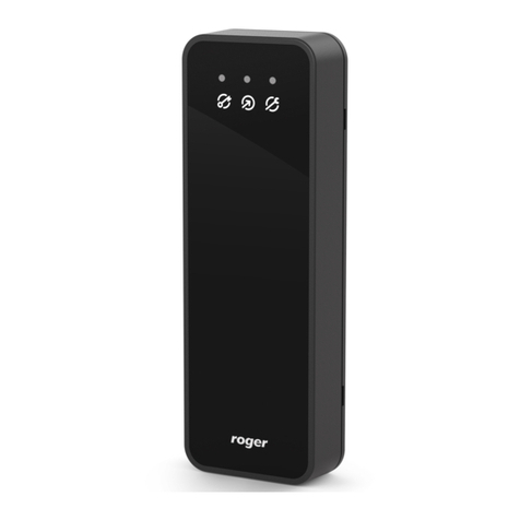
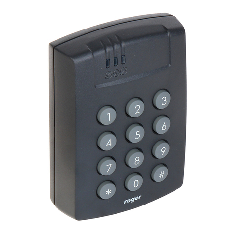
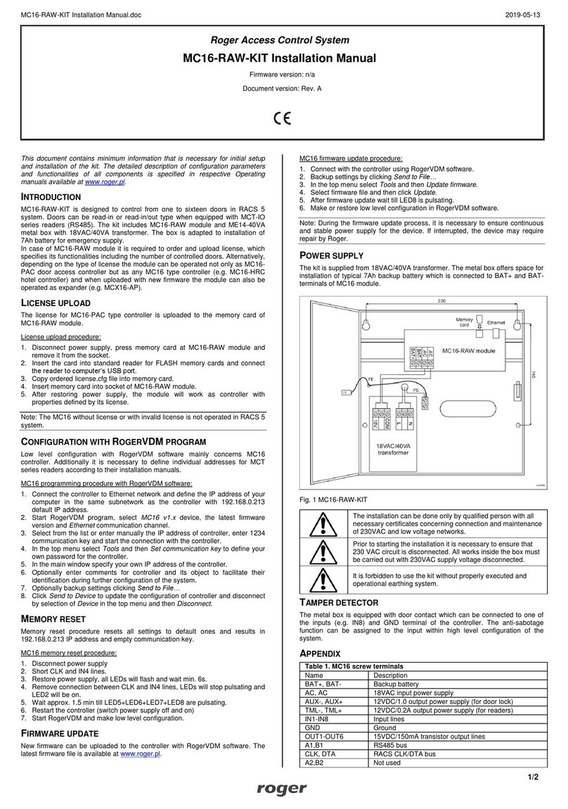
Roger MCT62E User manual

Roger Access Control System
MCT62E Operating Manual
Product version: 1.0
Firmware version: 1.1.18 or newer
Document version: Rev. C

MCT62E Operating Manual 31.08.2020
2/11
1. DESIGN AND APPLICATION
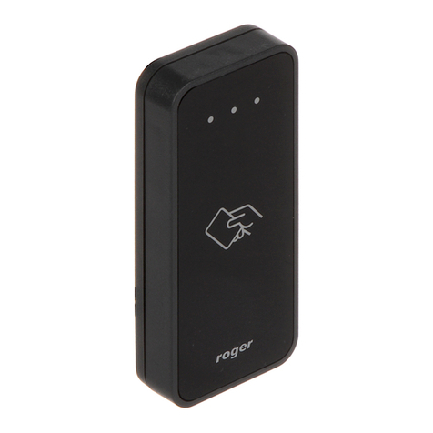
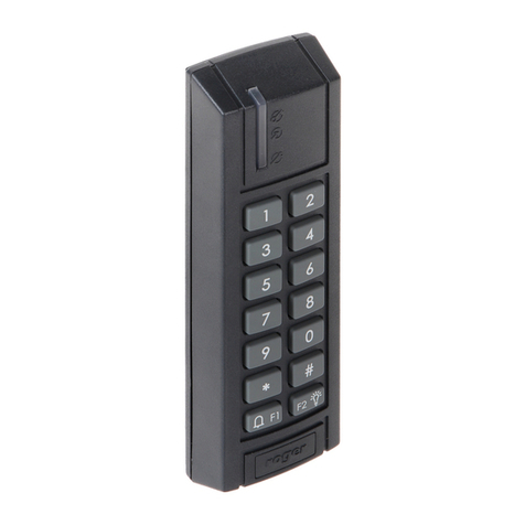
The MCT62E is an access terminal dedicated to RACS 5 system. The device enables identification of users
by EM125kHz (UNIQUE) proximity cards.
MCT62EM is connected to access controller through RS485 interface. Terminal can be installed in outdoor
locations without any additional protection measures.
Characteristics
RACS 5 system access terminal
EM125kHz (UNIQUE) proximity cards
3 LEDs indicators
Buzzer
RS485 interface
Tamper protection
Outdoor environment
Screw terminals
Power supply
The terminal requires power supply voltage in range of 11-15VDC. It can be supplied from MCX2D/MCX4D
expander of MC16-PAC-KIT, from MC16 access controller (e.g. TML output) or from dedicated power
supply unit. The supply wire diameter must be selected in such way that the voltage drop between supply
output and the device would be lower than 1V. The proper wire diameter is especially critical when device is
located in long distance from the supply source. In such a case the use of dedicated power supply unit
located close to the device should be considered. When separate power supply unit is used then its minus
should be connected to controller’s GND by means of signal wire with any diameter. It is recommended to
use UTP cable for connection of device to controller. The table below shows maximal UTP cable lengths in
relation to the number of wires used for power supply.
Table 1. Power supply cabling
Number of UTP wire pairs for power supply
Maximal length of power supply cable
1
150m
2
300m
3
450m
4
600m

MCT62E Operating Manual 31.08.2020
3/11
Fig. 1 MCT supply from MC16 access controller
Fig. 2 MCT supply from dedicated power supply unit
RS485 bus
The communication method with MC16 access controller is provided with RS485 bus which can encompass
up to 16 devices of RACS 5 system, each with unique address in range of 100-115. The bus topology can
be freely arranged as star, tree or any combination of them except for loop. The matching resistors
(terminators) connected at the ends of transmitting lines are not required. In most cases communication
works with any cable type (standard telephone cable, shielded or unshielded twisted pair etc.) but the
recommended cable is unshielded twisted pair (U/UTP cat.5). Shielded cables should be limited to
installations subject to strong electromagnetic interferences. The RS485 communication standard used in
the RACS 5 system guarantees proper communication in a distance of up to 1200 meters as well as high
resistance to interferences.
Note: Do not use more than single pair in UTP cable for RS485 communication bus.

MCT62E Operating Manual 31.08.2020
4/11
LED indicators
The terminal is equipped with three LED indicators which are used to signal integral functions and they can
be additionally programmed with other available functions within high level configuration (VISO).
Table 2. LED indicators
Indicator
Symbol
Colour
Integral functions
LED
STATUS
Red / green
Default colour of the indicator is red. If the terminal is assigned to
Alarm Zone then the LED indicates zone arming (red) or
disarming (green).
LED OPEN
Green
LED indicates access granting.
LED
SYSTEM
Orange
LED indicates card reading and can signal other system functions
including device malfunction.
Note: Synchronic pulsing of LED indicators signifies lost communication with MC16 controller.
Buzzer
The terminal is equipped with buzzer which is used to signal integral functions and it can be additionally
programmed with other available functions within high level configuration (VISO).
Tamper detector
Built-in tamper (sabotage) detector enables detection of unauthorized opening of device’s enclosure as well
as detachment of the enclosure from wall. The detector is internally connected to the terminal’s input. It
does not require low level configuration (RogerVDM) or any additional installation arrangements but it is
essential to mount front panel in such way as the tamper detector (fig. 4) would firmly press the back panel.
The detector requires high level configuration which consists in assignment of the function [133] Tamper
Toggle on the level of a Main Board of a controller in VISO software navigation tree.
Identification
EM125kHz proximity cards are widely used in office buildings. If it is necessary to ensure higher level of
security then MIFARE card readers e.g. MCT12M are recommended.
The technical characteristics of the device are guaranteed for RFID cards supplied by Roger. Cards from
other sources may be used, but they are not covered by the manufactures warranty. Before deciding to use
specific Roger products with third-party contactless cards, it is recommended to conduct tests that will
confirm satisfactory operation with the specific Roger device and software in which it operates.
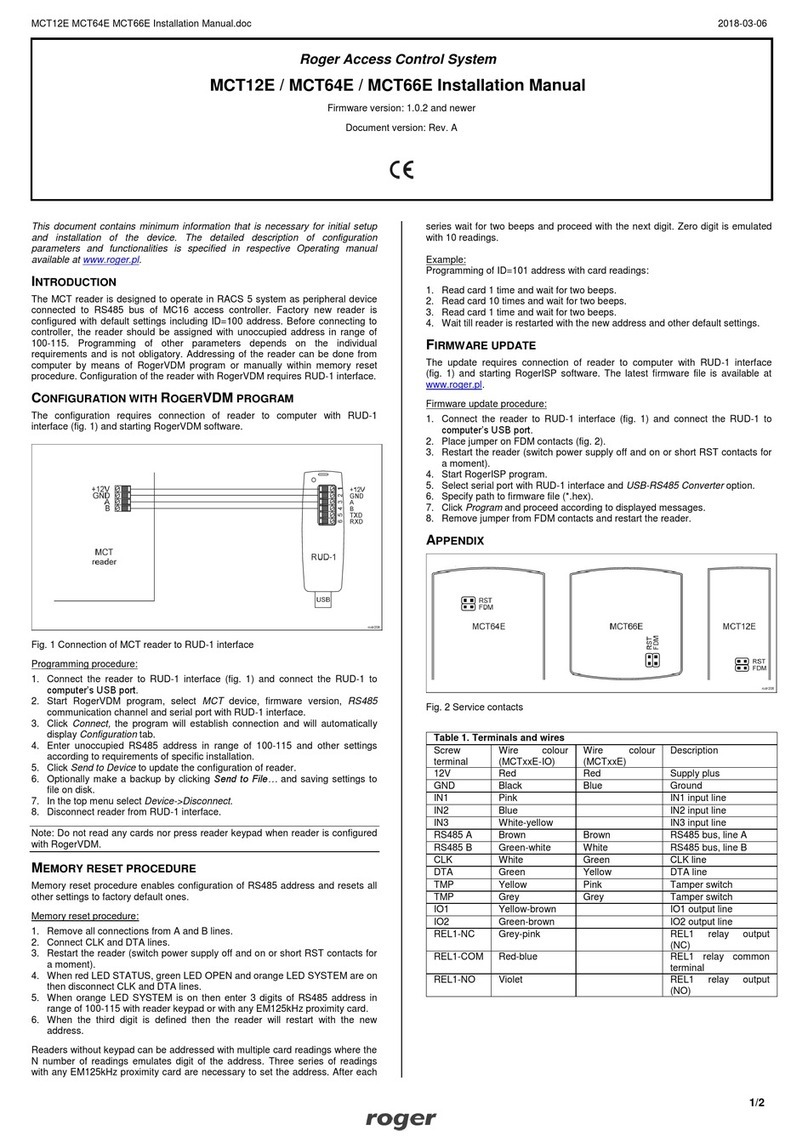
2. INSTALLATION
Table 3. Screw terminals
Name
Description
12V
12VDC power supply
GND
Ground
A
RS485 bus, line A
B
RS485 bus, line B

MCT62E Operating Manual 31.08.2020
5/11
Fig. 3 MCT62E installation

MCT62E Operating Manual 31.08.2020
6/11
Fig. 4 Programming jumpers
Installation guidelines
The terminal should be mounted on a vertical structure (wall) away from sources of heat and
moisture.
Front panel should be attached in such way as the tamper detector (fig. 4) would firmly press the
back panel.
All electrical connections should be done with disconnected power supply.
If the terminal and controller are not supplied from the same PSU then GND terminals of both
devices must be connected with any wire.
Clean front panel regularly by means of wet cloth and mild detergent. Do not clean by means of
abrasive materials and strong cleaners like alcohols, solvents, etc. Damages to screen surface are
beyond the scope of warranty.
3. OPERATION SCENARIOS
The terminal when connected to MC16 access controller can be at the same time used for access control
and Time&Attendance. The example of connection diagram for such scenario is shown in fig. 5 where inputs
and outputs from MC16 board are used. The terminal can also operate with MC16 controller using
MCX2D/MCX4D expanders as in case of M16-PAC-KIT series. Various scenarios of operation with MC16
controllers are presented in AN002 application note.

MCT62E Operating Manual 31.08.2020
7/11
Fig. 5 Typical connection diagram for the terminal and MC16 access controller
4. CONFIGURATION
Low level configuration (RogerVDM)
The purpose of low level configuration is to prepare device for operation in RACS 5 system.
Programming procedure with RogerVDM software:
1. Connect the reader to RUD-1 interface (fig. 6) and connect the RUD-1 to computer’s USB port.
2. Place jumper on MEM contacts (fig. 4).
3. Restart the reader (switch power supply off and on or short RES contacts for a moment) and orange
LED SYSTEM will pulsate.
4. Start RogerVDM program, select MCT device, firmware version, RS485 communication channel and
serial port with RUD-1 interface.
5. Click Connect, the program will establish connection and will automatically display Configuration tab.
6. Enter unoccupied RS485 address in range of 100-115 and other settings according to requirements of
specific installation.
7. Click Send to Device to update the configuration of reader.
8. Optionally make a backup by clicking Send to File… and saving settings to file on disk.
9. Remove jumper from MEM contacts and disconnect reader from RUD-1 interface.
Note: Do not read any cards when the device is configured with RogerVDM.

MCT62E Operating Manual 31.08.2020
8/11
Fig. 6 Connection to RUD-1 interface (low level configuration)
Table 4. List of low level parameters
Communication settings
RS485 address
Parameter defines device address on RS485 bus. Range: 100-115.
Default value: 100.
RS485 communication timeout [s]
Parameter defines delay after which device will signal lost
communication with controller. When set to 0 then signaling is
disabled. Range: 0-64s. Default value: 20s.
RS485 encryption
Parameter enables encryption at RS485 bus. Range: [0]: No, [1]: Yes.
Default value: [0]: No.
RS485 encryption key
Parameter defines key for encryption of communication at RS485 bus.
Range: 4-16 ASCII characters.
Optical signalisation
LED SYSTEM pulsing when card
near reader
Parameter enables LED SYSTEM (orange) pulsing when card is close
to the device. Range: [0]: No, [1]: Yes. Default value: [0]: No.
Backlight switching off when no
activity
Parameter enables backlight switching off after 20 s from the latest
card reading or key pressing. The backlight is restored again when
card or key is used. Range: [0]: No, [1]: Yes. Default value: [1]: Yes.
LED SYSTEM flash after card
read
Parameter enables short flash of LED SYSTEM (orange) when card is
read. Range: [0]: No, [1]: Yes. Default value: [1]: Yes.
Acoustic signalisation
Buzzer loudness level [%]
Parameter defines buzzer loudness level. When set to 0 then buzzer is
disabled Range: 0-100. Default value: 100.
Short sound after card read
Parameter enables short sound (beep) generating by buzzer when
card is read. Range: [0]: No, [1]: Yes. Default value: [1]: Yes.
Advanced settings
Stop card/PIN reading when
buffer full
Parameter enables to reject card/PIN reading by device till previous
card/PIN is transmitted to controller. Range: [0]: No, [1]: Yes. Default

MCT62E Operating Manual 31.08.2020
9/11
value: [0]: No.
Card/PIN buffer timeout [s]
Parameter defines time for card/PIN storing in device buffer. When the
time elapses the buffer is cleared even if card/PIN is not transmitted to
controller. Range: 1-64. Default value: 10.
Buffer overflow signalisation
Parameter enables LED SYSTEM (orange) switching on when
card/PIN buffer is full. Range: [0]: No, [1]: Yes. Default value: [0]: No.
AF type
Parameter defines authentication factor type returned by terminal.
Default value: [0010]: Number 40bits.
Long card read time [s]
Parameter defines long card read time. When set to 0 then long read
is disabled. Range: 0-64. Default value: 0.
Comments
DEV, KBD1, CDI1, IN1 (Tamper)
Parameter defines any text or comment which corresponds to the
device/object. It is later displayed in VISO program.
Manual addressing
Manual addressing procedure enables configuration of new RS485 address with all other settings
unchanged.
Manual addressing procedure:
1. Remove all connections from A and B lines.
2. Place jumper on MEM contacts (fig. 4).
3. Restart the reader (switch power supply off and on or short RES contacts for a moment) and orange
LED SYSTEM will pulsate.
4. Enter 3 digits of RS485 address in range of 100-115 using any EM125kHz card.
5. Remove jumper from MEM contacts and restart the reader.
Readers without keypad can be addressed with multiple card readings where the N number of readings
emulates digit of the address. Three series of readings with any EM125kHz proximity card are necessary to
set the address. After each series wait for two beeps and proceed with the next digit. Zero digit is emulated
with 10 readings.
Example:
Programming of ID=101 address with card readings:
1. Read card 1 time and wait for two beeps.
2. Read card 10 times and wait for two beeps.
3. Read card 1 time and wait for two beeps.
4. Wait till reader is restarted with the new address.
Memory reset procedure
Memory reset procedure resets all settings to factory default ones including ID=100 address.
Memory reset procedure:
1. Remove all connections from A and B lines.
2. Place jumper on MEM contacts (fig. 4).
3. Restart the reader (switch power supply off and on or short RES contacts for a moment) and orange
LED SYSTEM will pulsate.
4. Read any EM125kHz card 11 times.
5. Wait till reader confirms reset with long acoustic signal.
6. Remove jumper from MEM contacts and restart the reader.
MCT62E Operating Manual 31.08.2020
10/11
High level configuration (VISO)
The purpose of high level configuration is to define logical functioning of the terminal which communicates
with the MC16 access controller and it depends on applied scenario of operation. The example of access
control system configuration is given in AN006 application note which is available at www.roger.pl.
5. FIRMWARE UPDATE
The update requires connection of reader to computer with RUD-1 interface (fig. 7) and starting RogerVDM
software. The latest firmware file is available at www.roger.pl.
Firmware update procedure:
1. Connect the reader to RUD-1 interface (fig. 7) and connect the RUD-1 to computer’s USB port.
2. Place jumper on FDM contacts (fig. 4).
3. Restart the reader (switch power supply off and on or short RES contacts for a moment).
4. Start RogerVDM program and in the top menu select Tools and then Update firmware.
5. In the opened window select device type, serial port with RUD-1 interface and path to firmware file
(*.hex).
6. Click Update to start firmware upload with progress bar in the bottom.
7. When the update is finished, remove jumper from FDM contacts and restart the reader.
Fig. 7 Connection to RUD-1 interface (firmware update)
6. SPECIFICATION
Table 5. Specification
Supply voltage
Nominal 12VDC, min./max. range 10-15VDC
Current consumption
(average)
~50 mA
Tamper protection
Enclosure opening reported to access controller
Proximity cards
EM 125 kHz UNIQUE according to EM4100/4102
Reading range
Up to 5 cm
Distance
1200m maximal cable length for RS485 bus between controller and reader

MCT62E Operating Manual 31.08.2020
11/11
IP Code
IP65
Environmental class
(according to EN
50133-1)
Class IV, outdoor general conditions, temperature: -25°C to +60°C, relative
humidity: 10 to 95% (no condensation)
Dimensions H x W x D
100 x 40 x 25 mm
Weight
~100g
Certificates
CE
7. ORDERING INFORMATION
Table 6. Ordering information
MCT62E
EM 125 kHz access terminal
RUD-1
Portable USB-RS485 communication interface dedicated to ROGER access
control devices
8. PRODUCT HISTORY
Table 7. Product history
Version
Date
Description
MCT62E v1.0
06/2017
The first commercial version of product
This symbol placed on a product or packaging indicates that the product
should not be disposed of with other wastes as this may have a negative
impact on the environment and health. The user is obliged to deliver
equipment to the designated collection points of electric and electronic
waste. For detailed information on recycling, contact your local authorities,
waste disposal company or point of purchase. Separate collection and
recycling of this type of waste contributes to the protection of the natural
resources and is safe to health and the environment. Weight of the
equipment is specified in the document.
Contact:
Roger sp. z o.o. sp.k.
82-400 Sztum
Gościszewo 59
Tel.: +48 55 272 0132
Fax: +48 55 272 0133
Tech. support: +48 55 267 0126
E-mail: biuro@roger.pl
Web: www.roger.pl
Other manuals for MCT62E
1
Table of contents
Other Roger Control System manuals

Roger
Roger MCT12E User manual

Roger
Roger PR411DR-SET User manual

Roger
Roger B70/2DC Product manual

Roger
Roger MCI-2 User manual

Roger
Roger MCT82-FK User manual

Roger
Roger B73/LTM Product manual

Roger
Roger H85/TDR Product manual

Roger
Roger MCX2-BRD User manual

Roger
Roger IOS-1 User manual

Roger
Roger MCX402-BRD User manual

Roger
Roger PR611 User manual

Roger
Roger MCT80M User manual

Roger
Roger ASCD-1 User manual

Roger
Roger RKD32 User manual

Roger
Roger MCT64E-IO User manual

Roger
Roger H70/104AC Product manual

Roger
Roger H85/TDR Product manual

Roger
Roger PSD4D User manual

Roger
Roger MCT68ME-IO User manual

Roger
Roger MCI-5 User manual