S100 Extreme InstallaonSECTION C / PART 2 WIRE GUIDE INSTALLATION Cont ... WIRE GUIDES
Page 4
iii)i) i)iv) vi)
Tensioning Bracket - Floor/Side/Face Fix
Note: Refer to deducons for theorecal cable lengths. Measure, cut & crimp wire onsite to validate & ensure correct cable length.
Stud Terminal - Side/Face Fix
v)ii)
Refer
Crimp
Detail
Refer
Crimp
Detail
ii)
Refer
Swage
Detail
iii)
Refer
Crimp
Detail
Cable Length (C)
b) Ensure 2x crimps minimum per terminal. c) Minimum Crimp specificaon guide.
Minimum Crimp Specificaons
a) Ensure cable is fully inserted into terminal
Refer to table below for guide of crimp posion and sizing for all terminals.
BB
C1C2 A
NOTE: Ensure jaws of crimp tool close completely to acheive maximum
possible crimp strength - use dimension A as a guide).
Item
A (Crimp Hex AF)
B (Crimp spacing)
C1/C2 (Crimp length)
Size
(mm)
6.5
3.0
7.5
Size
(in)
0.26”
0.12”
0.30”
Note: Ensure end cap and terminal
have been inserted onto wire in the
correct order before crimping
Page. 10 EXTREME Wire Guide Installation Manual | v 3.0
2020 © Copyright All Rights Reserved Rollease Acmeda
SECTION 3 | INSTALLATION
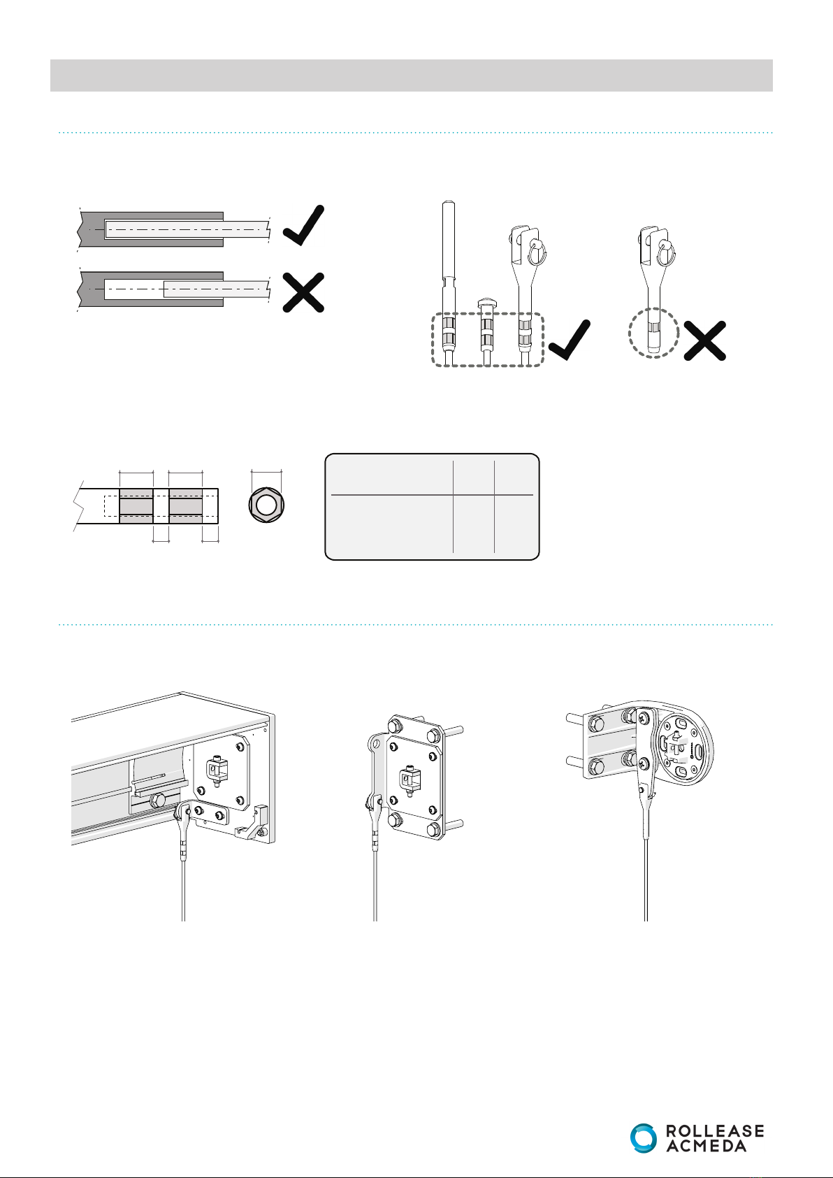
MINIMUM CRIMP SPECIFICATIONS
STEP 4 ATTACH FORK TERMINAL (CRIMPED) TO WIRE GUIDE ADAPTOR
a) Ensure cable is fully inserted into terminal b) Ensure 2x crimps minimum per terminal.
NOTE: Ensure jaws of crimp tool close completely to achieve maximum possible crimp strength - use dimension A as a guide.
c) Crimp guide - refer to tools section for recommended crimp tool.
Refer to table below for guide of crimp position and sizing for all terminals.
MOUNTING WIRE GUIDE TERMINALS