Seitron RGY S00 MBP4 Instruction Manual

1
>D@23(5$7,21,167$//$7,21$1'0$,17(1$1&(
2SHUDWLRQ
This is a microcontroller based device capable of monitoring the
gas concentration in up to 4 different zones: for each of these a
4 .. 20 mA transmitter can be wired for measurement and
detection of either L.P.G., Methane or Carbon Monoxide (CO).
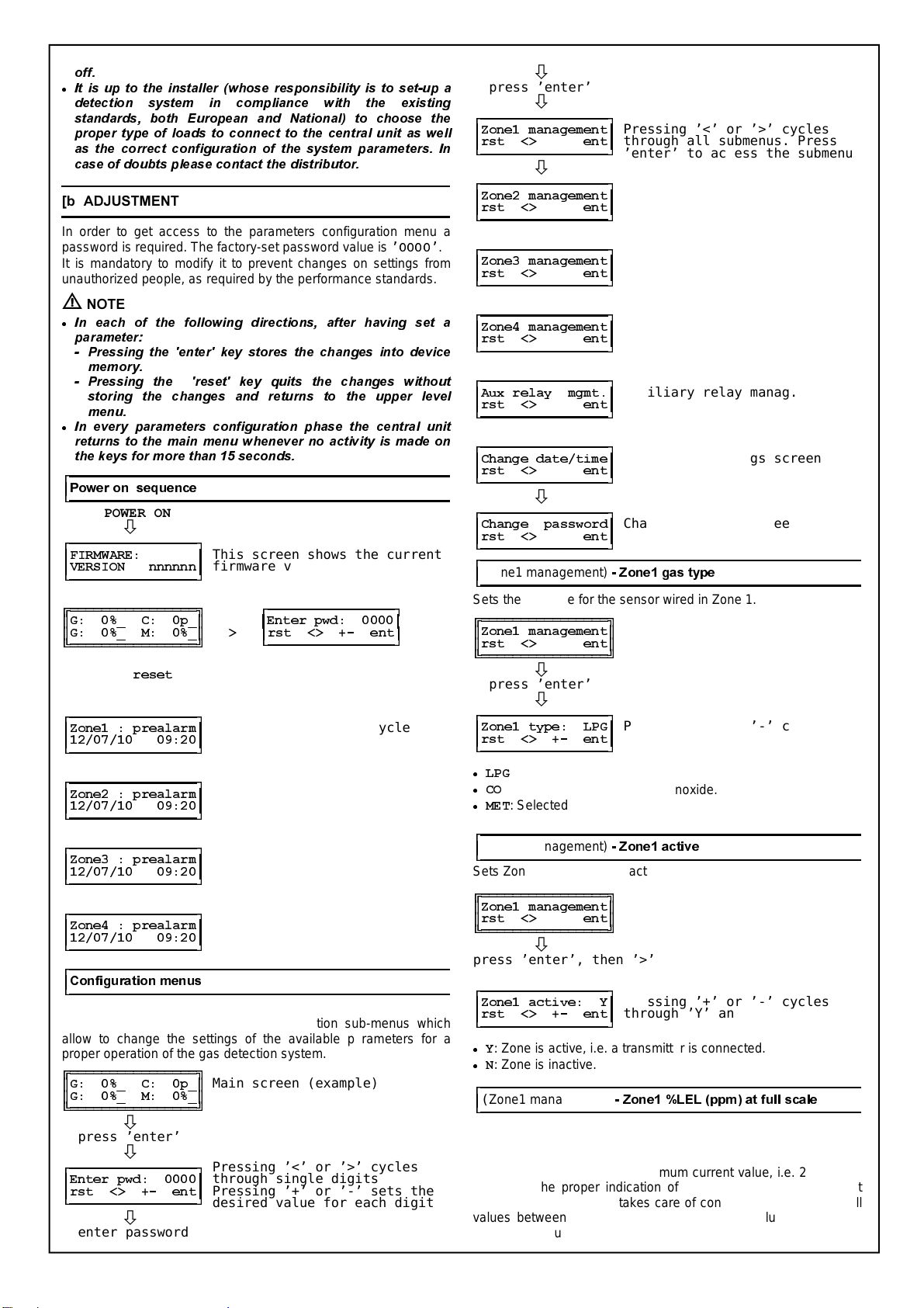
After power-up the display shows the following information:
]RQH ]RQH
),50:$5(
9(56,21QQQQQQ
]RQH ]RQH
where ’ nnnnnn ’ is the firmware version installed in the device.
This information will remain visible for about 2 seconds. After this
time the main information will be displayed (example):
]RQH ]RQH
*B&SB
*30$
]RQH ]RQH
Each zone provides the following information:
The first letter from left explains the transmitter type wired to the
central unit.
The transmitters which can be wired to the central unit can be
different for each zone; the detectable gases are the following:
- L.P.G.: display shows letter ’
*
’
- Methane (CH4): display shows letter ’
0
’
- Carbon Monoxide: display shows letter ’
&
’.
Values displayed on the right, in % L.E.L. (in case L.P.G. or
Methane transmitters are connected) or ppm (in case of Carbon
Monoxide) are the actual gas concentration values measured by
the transmitters. The last letter shown on the display for each zone
indicates the actual state of the relevant transmitter as explained
in the following:
’
B
:Active state (measuring, normal operation).
’
*
:Fault on the ’
*
’as transmitter (Iout=2 mA).
’
)
:’
)
’ault over the current loop (either short or open circuit
between any of the sensor wires: Iout=0 mA ).
’
3
: ’
3
’realarm state.
’
$
:’
$
’larm state. When ’
295
’ is shown in place of the
concentration value, this means that the upper limit of the
measuring range has been exceeded. The ’
295
’ state
corresponds to an input current value above 20mA.
3UHDODUPDQG$ODUPIXQFWLRQV
The central unit can manage separately the pre-alarm and alarm
conditions through two distinct, Normally Open, output relays.
In case the prealarm threshold is reached, the central unit enables
the relevant relay, which, in turn, closes its output contacts.
In case the alarm threshold state is reached the unit will also
enable the alarm relay thus closing the relevant output contact. At
the same time the central unit has stored the pre-alarm state first
and the alarm state later: the date and hour when the last has
happened will be retained in the central unit memory.
In case the gas concentration returns below the pre-alarm
threshold, the relevant relay will return to its normal operation
state or not, according to how the prealarm relay operating mode
was set in the configuration.
1RWH
For compliance with the current performance standards the
Alarm relay has always a latched operation and this mode cannot
be modified by the user. Whenever either an Alarm situation (’A’)
or an Overrange (’OVR’) situation is reached, this relay is kept
energised together with the internal buzzer and the red led until
the user intentionally presses for 3 seconds the ’
UHVHW
’ key.
$X[LOLDU\UHOD\
The central unit features one additional relay with changeover
contacts (SPDT) which can be activated according to events and
operating modes set by the installer through the relevant menu.
'LVSOD\RIWKHODVWDODUPVWDWH
The central unit can retain the date and hour of the last alarm
event happened in each zone.
These information can be read by the user at any time by pressing
for 3 seconds the ’
UHVHW
’ key when in main display screen, then
pressing ’<’ or ’>’ keys to cycle through the zones.
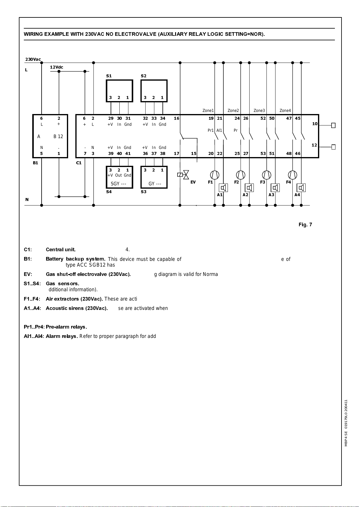
(OHFWULFDO:LULQJV
The central unit is normally powered with 230V~ mains voltage.
At terminals 6 and 7 the user can wire a battery backup system
whose purpose is to grant full functionality to the central unit even
in case of power failure (see section [m] for details).
Normally Closed (NC) output of the auxiliary relay is available at
terminals 15 and 16, while the Normally Open (NO) one is
available at terminals 16 and 17.
This output can be used either for driving ’general purpose’ loads
as a siren or an flashing light or, with proper configuration of the
relevant parameters, to drive a gas shut-off electrovalve.
Moreover this central unit features two single pole relay contacts
for each zone, one for prealarm and one for alarm.
The number of transmitters which can be wired to the central unit
is 4, each compliant with the 4..20 mA current loop system.
In order to make electrical wirings please refer to the suggested
wiring diagrams. Please also note that all the relay outputs of the
central unit do not feed power to the loads.
In other words all outputs are ’voltage free’, giving the user more
freedom to use loads with several operating voltages.
D :$51,1*
x
7KLV&HQWUDO8QLWLV127DSSURYHGIRULQVWDOODWLRQLQ$7(;
FODVVLILHG]RQHV
x
$OOZLULQJVZLWKUHPRWHVHQVRUVPXVWEHPDGHXVLQJZLUHV
ZLWK PPð PLQLPXP FURVV VHFWLRQ DQG QR ORQJHU WKDQ
P'RQRWXVHVDPHGXFWIRUVLJQDOZLUHVDQGPDLQV
x
,QFDVHRILQVWDOODWLRQZKHUHVWURQJ(0&GLVWXUEDQFHVDUH
SUHVHQWLWLV KLJKO\VXJJHVWHGWKHXVH RIVKLHOGHG FDEOHV
7KHVKLHOGPXVWEHFRQQHFWHGWRWKH *QG WHUPLQDORIWKH
UHOHYDQW]RQHRQWKH&HQWUDO8QLWVLGHRQO\
x
7KHDSSOLDQFHPXVWEHZLUHGWRWKHHOHFWULFPDLQVWKURXJKD
VZLWFK FDSDEOH RI GLVFRQQHFWLQJ DOO SROHV LQ FRPSOLDQFH
ZLWK WKH FXUUHQW VDIHW\ VWDQGDUGV DQG ZLWK D FRQWDFW
VHSDUDWLRQRIDWOHDVWPPLQDOOSROHV
x
,QVWDOODWLRQDQGHOHFWULFDOZLULQJVRIWKLVDSSOLDQFHPXVWEH
PDGHE\ TXDOLILHGWHFKQLFLDQV DQG LQ FRPSOLDQFH ZLWKWKH
FXUUHQWWHFKQLFDODQGVDIHW\VWDQGDUGV
x
%HIRUHZLULQJWKHDSSOLDQFHEHVXUHWRWXUQWKHPDLQVSRZHU
RGY S00 MBP4 SE 019179A0 200411
5*<60%3
=21(6 *$6 '(7(&7,21 &(175$/ 81,7 :,7+
566(5,$/287387
x
230V~ power supply
x
Controls up to 4 zones
x
Manages CO, L.P.G. and Methane (CH4) transmitters
x
Wide parameters configuration freedom
x
Last alarm conditions data retention
x
LCD backlight 2 x 16 characters display
x
9 modules DIN rail mount
x
RS232 serial output
VHLW
U
RQ
9LD3URVGRFLPR
,%$66$12'(/*5$33$9,
7HO
)D[
KWWSZZZVHLWURQLW
HPDLOLQIR#VHLWURQLW
F

2
RII
x
,WLVXSWRWKHLQVWDOOHUZKRVHUHVSRQVLELOLW\LVWRVHWXSD
GHWHFWLRQ V\VWHP LQ FRPSOLDQFH ZLWK WKH H[LVWLQJ
VWDQGDUGV ERWK (XURSHDQ DQG 1DWLRQDO WR FKRRVH WKH
SURSHUW\SHRIORDGVWRFRQQHFWWRWKHFHQWUDOXQLWDVZHOO
DV WKH FRUUHFW FRQILJXUDWLRQ RI WKH V\VWHP SDUDPHWHUV ,Q
FDVHRIGRXEWVSOHDVHFRQWDFWWKHGLVWULEXWRU
>E@$'-8670(17
In order to get access to the parameters configuration menu a
password is required. The factory-set password value is ’
’.
It is mandatory to modify it to prevent changes on settings from
unauthorized people, as required by the performance standards.
D127(
x
,Q HDFK RI WKH IROORZLQJ GLUHFWLRQV DIWHU KDYLQJ VHW D
SDUDPHWHU
3UHVVLQJ WKH HQWHU NH\ VWRUHV WKH FKDQJHV LQWR GHYLFH
PHPRU\
3UHVVLQJ WKH UHVHW NH\ TXLWV WKH FKDQJHV ZLWKRXW
VWRULQJ WKH FKDQJHV DQG UHWXUQV WR WKH XSSHU OHYHO
PHQX
x
,Q HYHU\ SDUDPHWHUV FRQILJXUDWLRQ SKDVH WKH FHQWUDO XQLW
UHWXUQVWRWKHPDLQPHQXZKHQHYHUQRDFWLYLW\LVPDGHRQ
WKHNH\VIRUPRUHWKDQVHFRQGV
3RZHURQVHTXHQFH
32:(521
Ø
),50:$5(
This screen shows the current
9(56,21QQQQQQ
firmware version
Ø
*B&SB
enter
(QWHUSZG
*B0B ! UVW!HQW
Ø
press ’
UHVHW
’ The following screens show the
for 3 seconds last event in each zone
Ø
=RQHSUHDODUP
Pressing ’<’ or ’>’ cycles
through all zones
Ø
=RQHSUHDODUP
Ø
=RQHSUHDODUP
Ø
=RQHSUHDODUP
&RQILJXUDWLRQPHQXV
From the main screen, showing the current state of all active
zones, the user can access all configuration sub-menus which
allow to change the settings of the available parameters for a
proper operation of the gas detection system.
*B&SB
Main screen (example)
*B0B
Ø
press ’enter’
Ø
Pressing ’<’ or ’>’ cycles
(QWHUSZG
through single digits
UVW!HQW
Pressing ’+’ or ’-’ sets the
desired value for each digit
Ø
enter password
Ø
press ’enter’
Ø
=RQHPDQDJHPHQW
Pressing ’<’ or ’>’ cycles
UVW!HQW
through all submenus. Press
’enter’ to access the submenu
Ø
=RQHPDQDJHPHQW
UVW!HQW
Ø
=RQHPDQDJHPHQW
UVW!HQW
Ø
=RQHPDQDJHPHQW
UVW!HQW
Ø
$X[UHOD\PJPW
Auxiliary relay manag. screen
UVW!HQW
Ø
&KDQJHGDWHWLPH
Date/time settings screen
UVW!HQW
Ø
&KDQJHSDVVZRUG
Change password screen
UVW!HQW
(Zone1 management)
=RQHJDVW\SH
Sets the gas type for the sensor wired in Zone 1.
=RQHPDQDJHPHQW
UVW!HQW
Ø
press ’enter’
Ø
=RQHW\SH/3*
Pressing ’+’ or ’-’ cycles
UVW!HQW
through gas LPG - CO - MET
x
/3*
: Selected gas is LPG.
x
&2
: Selected gas is Carbon Monoxide.
x
0(7
: Selected gas is Methane.
(Zone1 management)
=RQHDFWLYH
Sets Zone 1 as active or inactive.
=RQHPDQDJHPHQW
UVW!HQW
Ø
press ’enter’, then ’>’
Ø
=RQHDFWLYH<
Pressing ’+’ or ’-’ cycles
UVW!HQW
through ’Y’ and ’N’
x
<
: Zone is active, i.e. a transmitter is connected.
x
1
: Zone is inactive.
(Zone1 management)
=RQH/(/SSPDWIXOOVFDOH
Sets the full scale range for the sensor connected to Zone 1. The
value that must be entered here is the full scale value (in % LEL
for combustible or ppm for toxic) that the 4..20mA transmitter
measures when setting its maximum current value, i.e. 20mA.This
allows for the proper indication of the %LEL on the central unit
display. The central unit takes care of converting proportionally all
values between 4 and 20mA into the correct value from 0% (or
0ppm) to the full scale.
RGY S00 MBP4 SE 019179B0 200411

3
=RQHPDQDJHPHQW
UVW!HQW
Ø
press ’enter’, then ’>’ twice
Ø
Pressing ’+’ or ’-’ cycles
=RQH#IV
from 1% to 100% (LPG and MET)
UVW!HQW
and from 1ppm to 999ppp (CO)
D:$51,1*
x
7KHYDOXHWRVHWIRUWKLVSDUDPHWHULVVWULFWO\GHSHQGDQWRQ
WKHJDVWUDQVPLWWHUIHDWXUHVLHZKLFKYDOXHKDVEHHQVHW
DVIXOOVFDOHP$LQWKHWUDQVPLWWHUDWGHVLJQWLPH
x
:KHQ IRU D ]RQH D &2 FDUERQ PRQR[LGH WUDQVPLWWHU LV
VHOHFWHGLQRUGHUWRFRPSHQVDWHIRUVPDOOGULIWVLQWKH]HUR
OHYHOWKHFHQWUDOXQLWZLOOQRWVKRZYDOXHVZLWKLQWKH
RIWKHVHWIXOOVFDOHUDQJH
(Zone1 management)
=RQHSUHDODUPWKUHVKROG
Sets the pre-alarm threshold level for Zone 1, in % LEL for
combustible or ppm for toxic. This is the gas concentration value
at which a first level of attention is needed because the
environment is becoming dangerous.
=RQHPDQDJHPHQW
UVW!HQW
Ø
press ’enter’, then ’>’ 3 times
Ø
Pressing ’+’ or ’-’ cycles
=RQHSUDO
from 1% to 100% (LPG and MET)
UVW!HQW
and from 1ppm to 999ppp (CO)
D:$51,1*
x
,QFDVHWKHXVHUWULHVWRVHWDYDOXHIRUSUHDODUPKLJKHUWKDQ
WKDW IRU DODUP WKH FHQWUDO XQLW DXWRPDWLFDOO\ FRUUHFWV WKH
ODWWHUE\UDLVLQJLWWRWKHVDPHYDOXHDVWKHSUHDODUP
(Zone1 management)
=RQHDODUPWKUHVKROG
Sets the pre-alarm threshold level for Zone 1, in % LEL for
combustible or ppm for toxic.
=RQHPDQDJHPHQW
UVW!HQW
Ø
press ’enter’, then ’>’ 4 times
Ø
Pressing ’+’ or ’-’ cycles
=RQHDOUP
from 1% to 100% (LPG and MET)
UVW!HQW
and from 1ppm to 999ppp (CO)
D:$51,1*
x
,QFDVHWKHXVHUWULHVWRVHWDYDOXHIRUDODUPORZHUWKDQWKDW
IRU SUHDODUP WKH FHQWUDO XQLW DXWRPDWLFDOO\ FRUUHFWV WKH
ODWWHUE\ORZHULQJLWWRWKHVDPHYDOXHDVWKHDODUP
(Zone1 management)
=RQHSUHDODUPPRGH
Sets the pre-alarm relay retention mode (latching or non-latching).
In order to reset the relay in case the latched mode has been set
and the pre-alarm happened, just press for a few seconds the
’reset’ key: the display will show the date and time when the
prealarm was triggered.
Even in case the non-latched mode is selected, shoul a pre-alarm
event be triggered, the relevant date and time is acquired; it can
be displayed by pressing for a few seconds the ’reset’ key.
=RQHPDQDJHPHQW
UVW!HQW
Ø
press ’enter’, then ’>’ 5 times
Ø
=RQHSUPRGH2
Pressing ’+’ or ’-’ cycles
UVW!HQW
between ’O’ and ’L’
x
2
: Pre-alarm relay is non-latched.
x
/
: Pre-alarm relay is latched.
(Zone1 management)
=RQHDODUPPRGH
Sets the alarm relay retention mode (latching or non-latching). In
order to reset the relay in case the latched mode has been set and
the alarm happened, just press for a few seconds the ’reset’ key: the
display will show the date and time when the alarm was triggered.
Even in case the non-latched mode is selected, should a alarm
event be triggered, the relevant date and time is acquired; it can
be displayed by pressing for a few seconds the ’reset’ key.
=RQHPDQDJHPHQW
UVW!HQW
Ø
press ’enter’, then ’>’ 6 times
Ø
=RQHDOPRGH2
Pressing ’+’ or ’-’ cycles
UVW!HQW
between ’O’ and ’L’
x
2
: Alarm relay is non-latched.
x
/
: Alarm relay is latched.
$X[LOLDU\UHOD\PDQDJHPHQW
Configures the auxiliary relay operation.
$X[UHOD\PJPW
UVW!HQW
Ø
press ’enter’
Ø
$X[UORQ',6$%
Pressing ’+’ or ’-’ cycles
UVW!HQW
between ’DISAB’, ’FAULT’,
’PR+AL’, ’ALARM’, ’AL+FA’
Ø
$X[UORQ)$8/7
UVW!HQW
Ø
$X[UORQ35$/
UVW!HQW
Ø
$X[UORQ$/$50
UVW!HQW
Ø
$X[UORQ$/)$
UVW!HQW
x
',6$%
(disabled): the auxiliary relay operation is disabled.
x
$/$50
(alarm): the auxiliary relay is energized whenever the
unit detects a concentration level above the alarm threshold for
any zone.
x
)$8/7
(error): when this mode is selected the auxiliary relay is
energized whenever the unit detects either a fault in the
transmitter or a fault in the current loop for any of the zones.
x
35$/
(prealarm+alarm): the auxiliary relay is energized
whenever the unit detects a concentration level above the
prealarm threshold (i.e. also above the ’alarm’ threshold) for any
zone.
x
$/$50
(alarm): the auxiliary relay is energized whenever the
unit detects a concentration level above the alarm threshold for
any zone.
x
$/)$
(alarm+fault): the auxiliary relay is energized whenever
RGY S00 MBP4 SE 019179C0 200411

4
the unit detects a concentration level above the alarm threshold
or in case of a fault detected on any zone.
(Auxiliary relay management)
$X[LOLDU\UHOD\PRGH
Sets the auxiliary relay reset mode.
$X[UHOD\PJPW
UVW!HQW
Ø
press ’enter’, then ’>’
Ø
$X[UOPRGH231
Pressing ’+’ or ’-’ cycles
UVW!HQW
between ’OPN’ and ’LCK’
x
/&.
(locked): when the auxiliary relay is energized it remains
energized even in case the triggering event is removed, i.e. the
event is ’latched’. In order to reset the relay press the ’reset’
button.
x
231
(open): when the auxiliary relay is energized and then the
triggering event is removed, the relay returns to its former state,
i.e. the event is not ’latched’.
(Auxiliary relay management)
$X[LOLDU\UHOD\ORJLF
Sets the auxiliary relay logic.
$X[UHOD\PJPW
UVW!HQW
Ø
press ’enter’, then ’>’ twice
Ø
$X[UOPRGH125
Pressing ’+’ or ’-’ cycles
UVW!HQW
between ’NOR’ and ’REV’
x
125
(normal): any triggering event turns the relay on.
x
5(9
(reverse): the relay is normally energized. In case of a
triggering event the relay is de-energized. Use this mode when
a ’positive safety’ mode is required, because even in case of
lack of power supply the relay is de-energized, thus granting a
higher level of safety.
(Auxiliary relay management)
$X[LOLDU\UHOD\VWDUW
Sets the auxiliary relay start mode when power is first applied or
after a power lack.
$X[UHOD\PJPW
UVW!HQW
Ø
press ’enter’, then ’>’ 3 times
Ø
$X[UOVWUW',6
Pressing ’+’ or ’-’ cycles
UVW!HQW
between ’DIS’ and ’ENA’
x
',6
(disabled): the relay is activated according to the current
triggering events.
x
(1$
(enabled): the operator must start the operation by
intentionally arming the system. In other words the auxiliary
relay is kept indefinitely inactive (according to other mode
settings) until the operator intentionally presses the ’reset’
button. Choose this mode when a human intentional reset is
required after a power lack.
&KDQJHGDWHWLPH
Allows for setting of the current date and time.
Proper adjustment for current date and hour is mandatory for the
correct recording of the last alarm state.
This adjustment must be performed when the central unit is first
operated: from this moment on the unit will retain the correct date
and time even in case of power lack, thanks to the internal real
time clock and backup battery (allow 24h of charging time in case
of first operation).
&KDQJHGDWHWLPH
UVW!HQW
Ø
press ’enter’
Ø
Pressing ’<’ or ’>’ cycles
\\PPGGKKPP
through yy,mm,dd,hh,mm
Pressing ’+’ or ’-’ sets the
desired value
Ø
press ’enter’
to store data
&KDQJHSDVVZRUG
Sets new password.
The password is made of 4 numbers (no letters), each in the
range 0 .. 9.
&KDQJHSDVVZRUG
UVW!HQW
Ø
press ’enter’
Ø
Pressing ’<’ or ’>’ cycles
6HWQHZSZ
through single digits
UVW!HQW
Pressing ’+’ or ’-’ sets the
desired value for each digit
Ø
press ’enter’
stores data
D127(
x
)URPWKHPDLQVFUHHQSUHVVLQJDWWKHVDPHWLPHWKHWKUHH
NH\V ! UHVXOWV LQ UHVHWWLQJ WKH SDVVZRUG WR WKH
IDFWRU\YDOXHLHZLWKRXWFKDQJLQJWKHFRQILJXUDWLRQ
RIWKHUHPDLQLQJSDUDPHWHUV
x
)URP WKH PDLQ VFUHHQ SUHVVLQJ DW WKH VDPH WLPH WKH IRXU
NH\V ! UHVXOWV LQ UHVHWWLQJ WKH SDVVZRUG WR WKH
IDFWRU\YDOXHLHDVZHOODV$//RWKHUSDUDPHWHUV
0HVVDJHVRQWKHFHQWUDOXQLWGLVSOD\
In the following are described the messages on the central unit
display in different conditions. It is assumed that the Zone 1 has
been set for Methane gas and the actual concentration is varying.
]RQH ]RQH
0HVVDJHGLVSOD\HG
0BB
([SODQDWLRQ
’Zone inactive’
The relevant zone has not been activated. Remember that once a
transmitter has been wired to an input the relevant zone must also
be activated in configuration.
]RQH ]RQH
0HVVDJHGLVSOD\HG
0B
([SODQDWLRQ
’Normal operation’
This is what display shows during normal operation. Concentration
detected in this example is 0% L.E.L.
]RQH ]RQH
0HVVDJHGLVSOD\HG
0)
The yellow led flashes in correspondence with the symbol ’D’
and the buzzer sends an intermittent tone.
([SODQDWLRQ
’Fault in the current loop line’
Cable connecting the transmitter to the central unit present either
a short or an open circuit failure between any of the sensor wires.
RGY S00 MBP4 SE 019179D0 200411

5
Check and repair the current loop line regarding the faulty zone.
]RQH ]RQH
0HVVDJHGLVSOD\HG
0*
The yellow led is turned on in correspondence with the symbol ’D’
and the buzzer sends a continuous tone.
([SODQDWLRQ
’ Fault on the gas sensor ’.
The gas sensor is faulty and is setting 2mA on the current loop.
Check for the faulty transmitter and, eventually, replace it with a
new one.
]RQH ]RQH
0HVVDJHGLVSOD\HG
03
The red led flashes in correspondence with the symbol ’)’ and
the buzzer sends an intermittent tone.
([SODQDWLRQ
’Prealarm state’.
The prealarm concentration threshold in the zone under
monitoring has been exceeded. In this example a prealarm
threshold of 6% L.E.L. has been assumed (default factory value).
]RQH ]RQH
0HVVDJHGLVSOD\HG
0$
The red led is turned on in correspondence with the symbol ’)’
and the buzzer sends a continuous tone.
([SODQDWLRQ
’Alarm state’.
The alarm concentration threshold in the zone under monitoring
has been exceeded. In this example an alarm threshold of 13%
L.E.L. has been assumed (default factory value).
Alarm relay, red led and buzzer are latched as active until the
reset button is pressed.
]RQH ]RQH
0HVVDJHGLVSOD\HG
0295$
The red led is turned on in correspondence with the symbol ’)’
and the buzzer sends a continuous tone.
([SODQDWLRQ
’Over Range state’.
The upper limit of the measuring range has been exceeded.
Alarm relay, red led and buzzer and indication ’OVR’ are latched
as active until the reset button is pressed.
]RQH ]RQH
0HVVDJHGLVSOD\HG
0(025<)$8/7
&217$&76(59,&(
]RQH ]RQH
([SODQDWLRQ
’Memory fault’.
An error in one of the internal memories has been detected. The
operation is not reliable anymore. Contact service for device
replacement. Codes errors are: 01 (EEprom memory fault), 02
(Flash memory fault) and 03 (RAM memory fault).
>F@3(5,2',&$/&+(&.
A periodical check should include the following operations:
D
(every 3 .. 6 months):
)XQFWLRQDO FKHFN
of the correct
operation of the entire detection system by applying calibrated
gas to each remote sensor and check of the value displayed.
Also refer to the sensor User Manual for further information.
E
(every 12 months):
,QVWUXPHQWDOFKHFN
of the transfer function
of the central unit and correct detection of the abnormal
situations. This can be done by disconnecting the sensors from
inputs and forcing through a proper calibrator the input current
of each zone to the significant current values (e.g. 0mA: loop
broken, 2mA: fault, 4..20mA: normal operation, >20mA:
overrange).
>G@23(5$7,1*/,0,7$7,216
01. This device can be set either for flammable gases like
Methane (’M’) and LPG (’G’) or for toxic gases like CO (’C’).
02. For cross sensitivities refer to the remote sensor User Manual.
03. Response time T90:
Not applicable.
04. Temperature operating range:+5°C .. +55°C
05. Humidity operating range: 20% .. 90% RH (non cond.)
06. Pressure operating range: 800 .. 1100 hPa
07. Power supply range: 230V~ -15% +10% 50/60 Hz
08. Power absorption: 9,5VA
09. Electrical wirings: See section [a].
10. Batteries: See section [m].
11. Sample flow rate: Not applicable.
12. Warm-up time: Not applicable.
13. Stabilization time: Not applicable.
Contacts rating: zone relays: 8 x 2A@230V~ cos
auxiliary relay: 1 x 5A@250V~ cos
Prealarm threshold range: Methane and L.P.G.
1%..100% LEL
CO 1 .. 999 ppm
Alarm threshold range: Methane and L.P.G.
1%..100% LEL
CO 1 .. 999 ppm
Serial port: Standard RS232 (9600, 8, N, 1)
Protection degree: IP 00 (IP 30 in DIN rail cabinet)
Dimensions: 158 x 90 x 71 mm (L x A x P)
Weight: ~ 850 gr.
ATEX protection: This device must be installed in
NON-CLASSIFIED ATEX zones.
>H@6725$*(
Temperature: +5°C .. +55°C.
Humidity: 20% .. 90% RH (non cond.)
Pressure: 800 .. 1100 hPa
>I@/(/WRYYFRQYHUVLRQ
Please refer to the remote sensor User Manual.
>J@&217$0,1$176
Not applicable to the Central Unit. For remote sensor please refer
to the remote sensor User Manual.
>L@6$03/,1*/,1(6
Not applicable.
>M@$/$50$1')$8/76,*1$/6
Refer to sections [a] (OPERATION), [b] (ADJUSTMENT), [l]
(AUTOMATIC RESET) and to Fig. 5.
>N@7528%/(6+227,1*
x
3UREOHP
The password has been lost.
5HPHG\
Proceed with password reset as explained in section [b]
(ADJUSTMENT) under 'Change Password'.
x
3UREOHP
One channel (zone) shows the 'F' fault message.
3RVVLEOHFDXVH
The input current loop is broken or the transmitter is not
powered.
5HPHG\
Check connections between the transmitter and the central unit
searching for interruptions. Check also with a multimeter for the
presence of a voltage around 12Vdc between terminals '+V' and
'Gnd' of the relevant zone.
RGY S00 MBP4 SE 019179E0 200411

6
>O@$8720$7,&5(6(7
x
Pre-alarm relays action could be ’auto-resetting’ in case the
latching parameter (under Zone management - Zone pre-alarm
mode) has been set to ’O’ (open). Please refer to proper section
for further details.
x
Auxiliary relay action could be ’auto-resetting’ in case the
latching parameter (under Auxiliary relay management -
Auxiliary relay mode) has been set to ’OPN’ (open). Please refer
to proper section for further details.
>P@%$77(5,(60$,17(1$1&(
This central unit features input terminals (6 and 7) for an external
12Vdc power backup. Nonetheless it does not provide any
recharging function. This means that an external unit capable of
both providing 12V and recharging function for its battery must be
wired in case a power lack tolerant system is required. In the
diagrams provided in this User Manual the device ACC SGB 12
has been used as an example. The battery maintenance
operations must be based on what the manufacturer of this
additional device suggests.
>Q@63$5(3$576
This central unit has no user serviceable parts.
>R@$&&(6625,(6
This central unit has no accessories.
>S@0$5.,1*
)LJ
Marking label example.
D:$51,1*
x
7KLV&HQWUDO 8QLWLV 127DSSURYHGIRULQVWDOODWLRQLQ $7(;
FODVVLILHG]RQHV
>T@$'',7,21$/,1)250$7,21
No additional information regarding any special nature of the
device are needed.
In the view of a constant development of their products, the manufacturer
reserves the right for changing technical data and features without prior notice.
The consumer is guaranteed against any lack of conformity according to the
European Directive 1999/44/EC as well as to the manufacturer’s document
about the warranty policy. The full text of warranty is available on request from
the seller.
)LJ'LVSOD\FRQFHQWUDWLRQYV,QSXW&XUUHQW/(/
This chart is valid for the use of a 4..20mA transmitter which
delivers 20mA in correspondence of 100% L.E.L.. Setting of the
parameter ’Zone- @ fs’ must be 100% L.E.L..
)LJ'LVSOD\FRQFHQWUDWLRQYV,QSXW&XUUHQW/(/
This chart is valid for the use of a 4..20mA transmitter which
delivers 20mA in correspondence of 50% L.E.L.. Setting of the
parameter ’Zone- @ fs’ must be 50% L.E.L..
)LJ'LVSOD\FRQFHQWUDWLRQYV,QSXW&XUUHQWSSP
This chart is valid for the use of a 4..20mA transmitter which
delivers 20mA in correspondence of 500ppm. Setting of the
parameter ’Zone- @ fs’ must be 500ppm.
RGY S00 MBP4 SE 019179F0 200411
Type designation
Operational limitations
Class II Marking
Manufacturer address
Manufacturing Week-YearOperating voltage

7
>U@$33(1',;56287387
This Central Unit features a standard RS-232 output whose
purpose is to send to an receiving device (like a PC or a PLC) a
periodic complete report of the unit settings as well as the
measured values.
The RS232 output transmits with the following settings:
x
Speed: 9600 baud
x
Data: 8 bits
x
Parity: None
x
Stop: 1 bit
These settings are fixed and cannot be modified by the user.
An example of the messages sent by the Central Unit over the
RS232 port is in the following:
:B):B&5!/)!
3B)$8/7B/B5B6BSSSSB&5!/)!
$B&<BSBSB/BSB/B&5!/)!
%B0<BBB/BB/B&5!/)!
&B/<BBB/BB/B&5!/)!
'B&1BSBSB/BSB/B&5!/)!
9B\\PPGGBKKPPB0B/B&SB&SB&5!/)!
The explanation for each of the lines transmitted is in the
following.
6(783&21),*85$7,21675,1*VHQWHYHU\VHFRQGV
Firmware Version String
:B):B&5!/)!
where:
:
Character for command identification.
):
Characters for firmware version identification.
Firmware version (example: 014626).
&5!
CR character (Carriage Return = 0Dhex or 13dec).
/)!
LF character (Line Feed = 0Ahex or 10dec).
Alarm State and Control Mode of Aux Relay + Password
3B)$8/7B/B5B6BSSSSB&5!/)!
where:
3
Character for command identification.
)$8/7
Characters for identify the alarm state of the
auxiliary relay (DISAB, FAULT, PR+AL, AL+FA,
ALARM).
/
Control mode of auxiliary relay:
L = Locked,
O = Unlocked.
5
: Auxiliary relay activation mode:
N = Normal (unpowered when Off),
R = Reverse (powered when Off).
6
: Auxiliary relay “power up” status:
E = Enable (manual start operation, press reset
button).
D = Disable (automatic start operation).
SSSS
Password of the central unit.
&5!
CR character (Carriage Return = 0Dhex or 13dec).
/)!
LF character (Line Feed = 0Ahex or 10dec).
Zone 1 Setup Data
$B&<BSBSB/BSB/B&5!/)!
where:
$
Fixed, identifies Zone 1.
&
Gas type set in the zone (C = CO, M = Methane,
L = LPG).
<
Zone state ( Y = Active, N = Inactive ).
S
Full scale value + meas. Unit
(p=ppm, %=%L.E.L.).
/
Prealarm relay mode (L = locked, O = open)
S
Prealarm value + meas. Unit
(p=ppm, %=%L.E.L.).
S
Alarm value + meas. unit (p=ppm, %=%L.E.L.).
/
Alarm relay mode ( L= locked, O = open).
&5!
CR character (Carriage Return = 0Dhex or 13dec).
/)!
LF character (Line Feed = 0Ahex or 10dec).
Zone 2 Setup Data
%B0<BBB/BB/B&5!/)!
where:
%
Fixed, identifies Zone 2.
The remaining information meaning is the same as per Zone 1.
Zone 3 Setup Data
&B/<BBB/BB/B&5!/)!
where:
&
Fixed, identifies Zone 3.
The remaining information meaning is the same as per Zone 1.
Zone 4 Setup Data
'B&1BSBSB/BSB/B&5!/)!
where:
'
Fixed, identifies Zone 4.
The remaining information meaning is the same as per Zone 1.
0($685('9$/8(6675,1*VHQWHYHU\VHFRQGV
9B\\PPGGBKKPPB
0B/B&SB&SB&5!/)!
where:
9
Fixed, identifies Values string
\\PPGG
year + month + day set in the unit clock.
KKPP
hour and minute set in the unit clock.
0
Zone1: type (M,L,C) + measured value +
meas. unit (%,ppm).
/
Zone2: type (M,L,C) + measured value +
meas. unit (%,ppm).
&S
Zone3: type (M,L,C) + measured value +
meas. unit (%,ppm).
&S
Zone4: type (M,L,C) + measured value +
meas. unit (%,ppm).
&5!
CR character (Carriage Return = 0Dhex or
13dec).
/)!
LF character (Line Feed = 0Ahex or 10dec).
RGY S00 MBP4 SE 019179G0 200411

8
.H\ERDUGH[SODQDWLRQ
%X]]HU
Inside the central unit a buzzer is mounted which is activated any time an abnormal situation is detected.
5HVHWEXWWRQ
This key features two functions:
Quits the current menu and returns to the upper level menu.
When depressed more than 3 seconds, it shows the last alarm or prealarm that happened in all zones.
=RQH GLVSOD\ DUHD
In this area the user can read the actual gas concentration, the gas type for which the zone has been
programmed and the presence of any abnormal situation like pre-alarm, alarm, fault or overrange (please refer to proper section for
in depth description of the messages).
'LVSOD\
Through this 16 characters by 2 lines display all messages are shown to the user.
=RQHGLVSOD\DUHD
Same as point 3. but for Zone 2.
,QFUHDVH EXWWRQ
This key is used during configuration to increase values in numeric fields as well as to cycle through different
options for a given parameter.
6KLIWULJKWEXWWRQ
This key is used during configuration to move to the next submenu.
2Q2II LQGLFDWRU
This indicator shows the presence of power supply for the central unit, either from mains or from the eventual
battery backup system.
)DXOW LQGLFDWRU
This indicator shows the presence of a fault in a remote sensor or in the wiring to the central unit. Refer to proper
section for explanation of the possible causes of fault.
$ODUP LQGLFDWRU
This indicator shows the presence of an alarm or overrange in the system. The indicator flashes in case of pre-
alarm condition, while is steadily turned on in case of alarm or overrange. Refer to proper section for further details.
0DLQVLQGLFDWRU
This indicator is turned on when mains power is present. Together with On-Off indicator shows whether the unit is
working with mians power or battery backup power.
=RQHGLVSOD\DUHD
Same as point 3. but for Zone 3.
=RQHGLVSOD\DUHD
Same as point 3. but for Zone 4.
6KLIWOHIWEXWWRQ
This key is used during configuration to move to previous submenu.
'HFUHDVH EXWWRQ
This key is used during configuration to decrease values in numeric fields as well as to cycle through different
options for a given parameter.
(QWHUEXWWRQ
This key, when in configuration mode,
allows to enter the various menus and to confirm the selected parameter.
RGY S00 MBP4 SE 019179H0 200411
HQWHU
]RQH
UHVHW
]RQH
]RQH]RQH
8
9
10
11
1 2 3 4 5 6 7
12 13 14 15 16
)52173$1(/
)LJ

9
+
-
L
N+VInGnd
+V Out Gnd
+V In Gnd GndIn+V
+V In Gnd
+
-
L
N
+V Out Gnd
+V Out Gnd +V Out Gnd
/
9DF
1
NO NC
C
NO NONONONONONONO
CCCCCCCC
SGY --- SGY ---
SGY ---SGY ---
ACC SGB 12
)(9
$
)
$
)
$
)
$
6 6
6 6
&%
9GF
Zone1 Zone2 Zone3 Zone4
Pr1Al1 Pr2Al2 Pr3Al3 Pr4Al4
TX
GND
RGY S00 MBP4 RS-232
Aux RL
& &HQWUDOXQLW
Type RGY S00 MBP 4.
% %DWWHU\ EDFNXS V\VWHP
This device must be capable of supplying energy to the central unit in case of power lack. In this
diagram type ACC SGB12 has been used.
(9 *DVVKXWRIIHOHFWURYDOYH9DF
This wiring diagram is valid for Normally Closed type electrovalve.
66 *DV VHQVRUV
In this diagram remote sensors of the SGY--- series are used (please refer to the sensor User Manual for
additional information).
)) $LUH[WUDFWRUV9DF
These are activated when the pre-alarm relay in each single zone is activated.
$$ $FRXVWLFVLUHQV9DF
These are activated when the alarm relay in each single zone is activated.
AuxRL: Auxiliary relay
3U3U3UHDODUPUHOD\V
Refer to proper paragraph for additional information.
$O$O$ODUPUHOD\V
Refer to proper paragraph for additional information.
RS-232: Standard RS232 serial port (9600, 8, N, 1)
:,5,1*(;$03/(:,7+9$&1&(/(&7529$/9($8;,/,$5<5(/$</2*,&6(77,1* 125
)LJ
RGY S00 MBP4 SE 019179I0 200411

10
+
-
L
N+VInGnd
+V Out Gnd
+V In Gnd GndIn+V
+V In Gnd
+
-
L
N
+V Out Gnd
+V Out Gnd +V Out Gnd
/
9DF
1
NO NC
C
NO NONONONONONONO
CCCCCCCC
SGY --- SGY---
SGY ---SGY ---
ACC SGB 12
)(9
$
)
$
)
$
)
$
6 6
6 6
&%
9GF
Zone1 Zone2 Zone3 Zone4
Pr1 Al1 Pr2 Al2 Pr3 Al3 Pr4 Al4
TX
GND
RGY S00 MBP4 RS-232
Aux RL
& &HQWUDOXQLW
Type RGY S00 MBP 4.
% %DWWHU\ EDFNXS V\VWHP
This device must be capable of supplying energy to the central unit in case of power lack. In this
diagram type ACC SGB12 has been used.
(9 *DVVKXWRIIHOHFWURYDOYH9DF
This wiring diagram is valid for Normally Closed type electrovalve.
66 *DV VHQVRUV
In this diagram remote sensors of the SGY--- series are used (please refer to the sensor User Manual for
additional information).
)) $LUH[WUDFWRUV9DF
These are activated when the pre-alarm relay in each single zone is activated.
$$ $FRXVWLFVLUHQV9DF
These are activated when the alarm relay in each single zone is activated.
AuxRL: Auxiliary relay
3U3U3UHDODUPUHOD\V
Refer to proper paragraph for additional information.
$O$O$ODUPUHOD\V
Refer to proper paragraph for additional information.
RS-232: Standard RS232 serial port (9600, 8, N, 1)
:,5,1*(;$03/(:,7+9$&12(/(&7529$/9($8;,/,$5<5(/$</2*,&6(77,1* 125
)LJ
RGY S00 MBP4 SE 019179L0 200411

11
RGY S00 MBP4 SE 019179M0 200411
+
-
L
N+VInGnd
+V Out Gnd
+V In Gnd GndIn+V
+V In Gnd
+
-
L
N
+V Out Gnd
+V Out Gnd +V Out Gnd
/
9DF
1
NO NC
C
NO NONONONONONONO
CCCCCCCC
SGY --- SGY---
SGY ---SGY ---
ACC SGB 12
)(9
$
)
$
)
$
)
$
6 6
6 6
&%
9GF
Zone1 Zone2 Zone3 Zone4
Pr1 Al1 Pr2 Al2 Pr3 Al3 Pr4 Al4
TX
GND
RGY S00 MBP4 RS-232
Aux RL
& &HQWUDOXQLW
Type RGY S00 MBP 4.
% %DWWHU\ EDFNXS V\VWHP
This device must be capable of supplying energy to the central unit in case of power lack. In this
diagram type ACC SGB12 has been used.
(9 *DVVKXWRIIHOHFWURYDOYH9DF
This wiring diagram is valid for Normally Closed type electrovalve.
66 *DV VHQVRUV
In this diagram remote sensors of the SGY--- series are used (please refer to the sensor User Manual for
additional information).
)) $LUH[WUDFWRUV9DF
These are activated when the pre-alarm relay in each single zone is activated.
$$ $FRXVWLFVLUHQV9DF
These are activated when the alarm relay in each single zone is activated.
AuxRL: Auxiliary relay
3U3U3UHDODUPUHOD\V
Refer to proper paragraph for additional information.
$O$O$ODUPUHOD\V
Refer to proper paragraph for additional information.
RS-232: Standard RS232 serial port (9600, 8, N, 1)
127(
7KLVGLDJUDP IHDWXUHV DSRVLWLYH VDIHW\)RU SURSHURSHUDWLRQWKH SDUDPHWHU$X[LOLDU\UHOD\ ORJLF PXVW EHVHWWR
5(9VRWKDWDQ\ODFNRISRZHUZRXOGUHVXOWLQWKHUHOD\RSHQLQJDQGYDOYHGHDFWLYDWLRQ
:,5,1* (;$03/( :,7+ 9$& 1& (/(&7529$/9( :,7+ 326,7,9( 6$)(7< $8;,/,$5< 5(/$< /2*,& 6(77,1* 5(9
6((127(
)LJ

12
& &HQWUDOXQLW
Type RGY S00 MBP 4.
% %DWWHU\ EDFNXS V\VWHP
This device must be capable of supplying energy to the central unit in case of power lack. In this
diagram type ACC SGB12 has been used.
(9 *DVVKXWRIIHOHFWURYDOYH9GF
This wiring diagram is valid for Normally Closed type electrovalve.
66 *DV VHQVRUV
In this diagram remote sensors of the SGY--- series are used (please refer to the sensor User Manual for
additional information).
)) $LUH[WUDFWRUV9DF
These are activated when the pre-alarm relay in each single zone is activated.
$$ $FRXVWLFVLUHQV9DF
These are activated when the alarm relay in each single zone is activated.
AuxRL: Auxiliary relay
3U3U3UHDODUPUHOD\V
Refer to proper paragraph for additional information.
$O$O$ODUPUHOD\V
Refer to proper paragraph for additional information.
RS-232: Standard RS232 serial port (9600, 8, N, 1)
+
-
L
N+VInGnd
+V Out Gnd
+V In Gnd GndIn+V
+V In Gnd
+
-
L
N
+V Out Gnd
+VOutGnd +VOutGnd
/
9DF
1
NO NC
C
NO NONONONONONONO
CCCCCCCC
SGY--- SGY---
SGY ---SGY ---
ACC SGB 12
)(9
$
)
$
)
$
)
$
6 6
6 6
&%
9GF
Zone1 Zone2 Zone3 Zone4
Pr1 Al1 Pr2 Al2 Pr3 Al3 Pr4 Al4
TX
GND
RGY S00 MBP4 RS-232
Aux RL
:,5,1*(;$03/(:,7+9'&1&(/(&7529$/9($8;,/,$5<5(/$</2*,&6(77,1* 125
)LJ
RGY S00 MBP4 SE 019179N0 200411
Other Seitron Gas Detector manuals

Seitron
Seitron SEGUGIO DOUBLE RD XSM1 SE Series User manual

Seitron
Seitron SEGUGIO WIRELESS Series User manual

Seitron
Seitron SGI 1 M Series User manual

Seitron
Seitron BE COOL R1 User manual

Seitron
Seitron BEAGLE plus User manual

Seitron
Seitron POLF02 User manual

Seitron
Seitron BEAGLE L User manual

Seitron
Seitron RI-01RM User manual

Seitron
Seitron RGY 000 MBP4 Instruction Manual

Seitron
Seitron BEAGLE User manual